
Related Manuals for Rohde & Schwarz NGMO1


Summary of Contents for Rohde & Schwarz NGMO1
- Page 1 Service Manual Power Supply NGMO1 Power Supply NGMO2 192.1500.21 and 192.1500.24 5707.2571.82...
- Page 2 Service Manual Power Supply NGMO1 and Power Supply NGMO2 Edition: May 2014 Version: 3.00 All rights reserved, including translation into foreign languages. No part of this manual may be re- produced or reworked using electronic systems, duplicated or distributed in any form (photocopy- ing, microfilm or any other process), not even for instructional purposes, without written permis- sion from ROHDE &...
- Page 3 Safety Instructions This unit has been designed and tested in accordance with the EC Certificate of Conformity and has left the manufacturer’s plant in a condition fully complying with safety standards. To maintain this condition and to ensure safe operation, the user must observe all instructions and warnings given in this operating manual.
- Page 4 Safety Instructions Applicable local or national safety regulations and 12. Equipment returned or sent in for repair must be rules for the prevention of accidents must be packed in the original packing or in packing with observed in all work performed. electrostatic and mechanical protection.
-
Page 5: Table Of Contents
Contents Power Supply NGMO Contents User Information NGMO-Versions 1.1.1 NGMO1 1.1.2 NGMO2 Purpose of the Handbook Important User Notes Explanation of Symbols Customer Service Service Addresses 2.1.1 Technical Support 2.1.2 Ordering Spare Parts and Test Equipment Safety General Safety Instructions... - Page 6 Power Supply NGMO Contents Calibration Procedure The Calibration Entry ID got lost 7-10 Repair Function Tests by using the Service Functions 8.1.1 Selecting the Interfaces to be used 8.1.2 Setting the Electronic Serial Number 8.1.3 Setting the NGMO Device Name (from firmware version 1.10) 8.1.4 Communication Test with Analog Boards 8.1.4.1...
- Page 7 Contents Power Supply NGMO 10.1 OUTPUT A / OUTPUT B (Channel A /Channel B) 10-2 10.2 CONTROL I/O (Relay Connector, SUB 15, Male) 10-3 11 Bill of Materials 11-1 12 Software Update 12-1 12.1 Components List 12-1 12.2 Running the Update 12-1 3.00 / 05-2014...
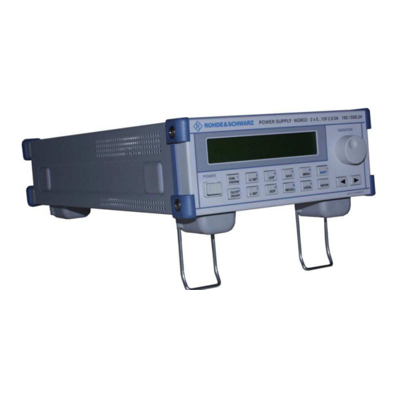
- Page 8 Power Supply NGMO User Information Figures Fig. 4-1 Power Supply NGMO2, Overall view ............... 4-1 Fig. 4-2 Power Supply NGMO, Function block diagram ............4-5 Fig. 5-1 Power Supply NGMO2, Operation elements ............5-1 Fig. 5-2 Power Supply NGMO2, Connections on rear side of unit ......... 5-4 Fig.
-
Page 9: User Information
Power Supplies, such differences will be specially emphasized. The designation NGMO is used wherever the description applies for all versions. 1.1.1 NGMO1 The Power Supply NGMO1 consists of the following assemblies: • Keyboard with LC Display • Processor board •... -
Page 10: Important User Notes
Power Supply NGMO User Information Apart from the Service Manual, the Operating Manual, the health and safety regulations applicable in the place where the unit is used, as well as the applicable technical standards and regulations on safety and correct working are to be observed. The operating organisation is to extend the service instructions, as necessary, with information on national health and safety regulations, and environmental regulations. -
Page 11: Explanation Of Symbols
User Information Power Supply NGMO Explanation of Symbols The Power Supply NGMO was produced according to the generally ac- cepted regulations governing the technology and current status of sci- ence and technology. However, it is impossible to design hazard-free electrical equipment. In order to guarantee a sufficient level of safety for personnel working with the Power Supply NGMO, safety regulations must be observed. - Page 12 Power Supply NGMO User Information 3.00 / 05-2014...
-
Page 13: Customer Service
Customer Service Power Supply NGMO 2 Customer Service The addresses of the Rohde & Schwarz Head Offices, Branch Offices and Service Stations are listed on the internet pages: http://www.rohde-schwarz.com Service Addresses 2.1.1 Technical Support If you have any technical queries concerning this Rohde & Schwarz equipment, please call us, we will be glad to help. - Page 14 Power Supply NGMO Customer Service 3.00 / 05-2014...
-
Page 15: Safety
Safety Power Supply NGMO 3 Safety General During service work on the Power Supply NGMO, the safety regula- tions applicable in the country of use must be observed. NOTE Only personnel authorized by ROHDE & SCHWARZ may open the Power Supply NGMO. If the safety regulations for the Power Supply NGMO are disre- garded, ROHDE &... - Page 16 Power Supply NGMO Safety 3.00 / 05-2014...
-
Page 17: Unit Description
The NGMO is more, than just a power supply for conventional test and measurement equipment, - it is an accurate, multipurpose electronic device with two separate supply and measurement channels (NGMO2 only, NGMO1 only Channel A) which can be used as the following: • high speed voltage source, •... -
Page 18: Function Description
• Processor board • Keyboard / Display • Analog board ”A“ (NGMO1) • Analog boards ”A“ and ”B“ (NGMO2) 4.2.1 Prozessor Board Apart from the control processor, its periphery and all data interfaces the processor board also contains the rectification and filtering for the electric power supply of the overall unit. -
Page 19: Keyboard / Display
Unit Description Power Supply NGMO A serial interface RS232 and an IEEE-488-2 connection accommodate remote control. Apart from that the unit contains a Control Interface with control lines and relay drivers. 4.2.2 Keyboard / Display The NGMO control unit consists of the keyboard with rotary transducer and the detached LC display. - Page 20 Power Supply NGMO Unit Description processor (DSP) each, which takes over the control of the board and the real-time evaluation of the measuring values. All measurements are accomplished via a fast 16Bit-A/D-converter with a series-connected multiplexer, various D/A-converters are used to ad- just the output variables.
-
Page 21: Fig. 4-2 Power Supply Ngmo, Function Block Diagram
Unit Description Power Supply NGMO Fig. 4-2 Power Supply NGMO, Function block diagram 3.00 / 05-2014... - Page 22 Power Supply NGMO Unit Description 3.00 / 05-2014...
-
Page 23: Operation
Fig. 5-1 shows the Operation Elements for the Power Supply NGMO2. NOTE: Operation elements and Start Up functions of the Power Supply NGMO1 are identical with the NGMO2. Operation elements for channel B must in this case be ignored. Readings in the LC Display correspond with the respective Power Supply. - Page 24 Power Supply NGMO Operation Function Type Function element ARROW KEYS (left and right) keys • When no other function is selected, the LCD contrast can be adjusted with the arrow keys. • The arrow key moves the cursor to the numerical input you want to make, •...
- Page 25 Operation Power Supply NGMO Function Type Function element 7; Current setting Press I-SET to set the output current limit of the channel you have selected. The value you want can be entered and modified after you press the SHIFT key or by turning the variation knob. The max.
-
Page 26: Fig. 5-2 Power Supply Ngmo2, Connections On Rear Side Of Unit
Power Supply NGMO Operation Connections on Rear Side of Unit Fig. 5-2 Power Supply NGMO2, Connections on rear side of unit Pos. Function Output Channel A / DVMA in Output Channel B / DVMB in Mains Connector Mains Voltage Selector USB Interface Connector IEEE-488-2 Interface Connector RS232 Interface Connector... - Page 27 Operation Power Supply NGMO Start Up 5.3.1 NGMO Line Power Connection and Power-up The NGMO operates from a line voltage in the range 120/230 VAC at a frequency between 47 and 63 Hz. Proceed as follows to connect the NGMO to the AC line and turn on: Before plugging in the power cable, make sure that the power switch is off (the “POWER“...
- Page 28 B in the NGMO2. Currently only type 3 is available. For further information concerning the settings on the Power Supply and the readings in the display please refer to the Operator Manual for the Power Supply NGMO1 / NGMO2. 3.00 / 05-2014...
-
Page 29: Maintenance
Maintenance Power Supply NGMO 6 Maintenance Attention! Work on the Power Supply NGMO must be performed in strict compliance with the ESD-regulations (electrostatic discharge). General In order to maintain the function and the durability of the Power Supply NGMO, care, maintenance and inspection tasks must be performed at specified intervals. -
Page 30: Cleaning
Power Supply NGMO Maintenance Cleaning The following devices and materials are recommended for cleaning the Power Supply NGMO: • soft, lint-free cloths Attention! Do not use aggressive cleaning agents to clean the Power Supply NGMO. 3.00 / 05-2014... -
Page 31: Calibration
Calibration Power Supply NGMO 7 Calibration Calibration Equipment Test equipment Technical data Supplier Part number Pos. Calibration adapter Rohde & Schwarz 3544.3544.00 Cologne 15pin D-Sub plug/plug interface Scope of delivery Rohde & Schwarz cable of the calibration Cologne adapter Digital voltmeter Accuracy: 0.001 % 7.1.1 Calibration Adapter... -
Page 32: Calibration Set-Up
Power Supply NGMO Calibration Calibration Set-up Fig. 7-2 Power Supply NGMO, Calibration set-up 3.00 / 05-2014... -
Page 33: Calibration Procedure
Calibration Power Supply NGMO Calibration Procedure In the following you are taken through the complete calibration proce- dure for one of the power supply channels. NOTE: The NGMO must be switched on one hour before the calibration process in order to reach the correct operating temperature. - Page 34 Power Supply NGMO Calibration The display must show the following: Firmw.:x.yy CAL:zzzz Lst CAL on: yy.mm.dd • x.yy is the firmware version currently loaded in the NGMO. x is the major version number and yy is the minor version number. •...
- Page 35 Calibration Power Supply NGMO Input of a new Entry ID Next, you are asked for a new calibration entry ID. If you want to set a new ID you can enter it here. After verification this new entry ID is stored internally in the NGMO.
- Page 36 Power Supply NGMO Calibration 11. Enter the Measuring value. Use either the variation knob or numerical entry keys (press shift key to initiate the numerical input) to enter the measured value that is displayed on the DVM. 12. Press ENTER. The display must show the following: Look at DVM and ent.
- Page 37 Calibration Power Supply NGMO 16. Enter the resistance value. Use either the variation knob or numerical entry keys to enter the exact resistor value. 17. Press ENTER. NOTE: When using the calibration set-up specified in section 7.2, the following display may be neglected. The display must show the following: Connect known 33 Ohm Resistor to out.term...
- Page 38 Power Supply NGMO Calibration The display must show the following: Conn. Known 3.3 Kohm Resistor to out.term 21. Press ENTER. The display must show the following: Enter exact Resistor value: 3xxx.x Ohms NOTE: The values of the resistors installed in the calibration adapter can be taken from the calibration certificate supplied with the calibration adapter.
- Page 39 Calibration Power Supply NGMO The display must show the following: Enter new CAL. Date: YY/MM/DD: yy/mm/dd • yy is the current year (from 01 to 99). • mm is the current month (from 01 to 12) • dd is the current day (from 01 to 31 – depends on the selected month): 25.
-
Page 40: The Calibration Entry Id Got Lost
Power Supply NGMO Calibration The Calibration Entry ID got lost NOTE: Only personnel authorized by ROHDE & SCHWARZ may open the NGMO. If the safety regulations for the Power Supply NGMO are disre- garded, ROHDE & SCHWARZ GmbH & Co KG will not assume liability for any resulting damage and all warranties will become null and void. - Page 41 Calibration Power Supply NGMO After a short time, the NGMO displays the following message: Really set cal.entry ID to 0. (ENTER=YES) Press ENTER. If you press the ENTER key, the current calibration entry ID will be overwritten with a zero. Any other key aborts this function. Remove the calibration entry ID jumper.
- Page 42 Power Supply NGMO Calibration 7-12 3.00 / 05-2014...
-
Page 43: Repair
Power Supply NGMO2 as an example. This version is equipped with analog boards A and B. The function tests also apply for NGMO1, in which case the tests are limited to analog board A. All descriptions and specifications concerning channel B must be ignored. -
Page 44: Selecting The Interfaces To Be Used
Power Supply NGMO Repair 8.1.1 Selecting the Interfaces to be used IEEE-488-2 Interface COM Interface: National NI-488-2 Communicator If the serial interface is used, this should be manually set to „ON“, under menu option 31, beforehand. Apart from that the serial interface parameters must be adapted to the parameters of the controlling computer. -
Page 45: Setting The Electronic Serial Number
Repair Power Supply NGMO 8.1.2 Setting the Electronic Serial Number Function test The electronic serial number is stored in the EEPROM of the Power Supply NGMO. • Read out the serial number with the following remote command: *IDN? Fault rectification In case of an occurring fault: •... -
Page 46: Setting The Ngmo Device Name (From Firmware Version 1.10)
Power Supply NGMO Repair 8.1.3 Setting the NGMO Device Name (from firmware ver- sion 1.10) Function test The device name is stored in the EEPROM of the Power Supply NGMO. • Read out the serial number with the following remote command: *IDN? Fault rectification In case of an occurring fault:... -
Page 47: Communication Test With Analog Boards
Repair Power Supply NGMO 8.1.4 Communication Test with Analog Boards Description The following remote commands can be used to test whether the communication between the main computer on the processor board and the two satellite computers on the analog boards works correctly. For this purpose a test number can be transmitted to one of the two satellite computers, which can subsequently be read back in a second step. -
Page 48: Display Blank Test
Power Supply NGMO Repair 8.1.5 Display Blank Test Description This test is performed to determine whether all pixels of the LC display can be switched off. After initiating the test the LC display should not show any pixels. • Function test Switch off all pixels of the LC display using the following remote command: rus:service:select:function:test 1... -
Page 49: Display Unblank Test
Repair Power Supply NGMO 8.1.6 Display Unblank Test Description This test is performed to determine whether all pixels of the LC display can be switched on. After starting this test the LC-display should show grey blocks with all pixels in place. •... -
Page 50: Keyboard And Knob Test
Power Supply NGMO Repair 8.1.7 Keyboard and Knob Test Description This test enables the user to check whether all keyboard keys and the rotary transducer work correctly. Function test After starting operate the rotary transducer first. When turning clockwise the numerical value in top right hand corner of the display must increase by 1 with every step of the rotary transducer, and decrease by 1 when turning anti-clockwise. - Page 51 Repair Power Supply NGMO The following bits are set to 0 when: Turning rotary transducer anti-clockwise Bit 15 Turning rotary transducer clockwise Bit 14 Right hand arrow key Bit 13 Left hand arrow key Bit 12 ENTER key Bit 11 SHIFT key Bit 10 RECALL (9) key...
-
Page 52: Control I/O Test
Power Supply NGMO Repair 8.1.8 Control I/O Test Description The Control I/O test checks the functionality of the signals on the “Control I/O” plug on the back NGMO. For this purpose the NGMO calibration adapter must be connected as shown in Fig. 8-1 for the following test: Test set-up Fig. - Page 53 Repair Power Supply NGMO • Function test Switch on test 4 with the following remote command: rus:service:select:function:test 4 • The display shows the following message: Control I/O test • Interrogate test 4: rus:service:select:function:test? If no error is present, the returned value of the function should be Function test The following bits are set when: Slave I/O fault channel B Bit 9...
-
Page 54: Inhibit On
Power Supply NGMO Repair 8.1.9 INHIBIT ON Description This function is used to test whether the output drivers of the NGMO can be switched off via the Inhibit lines. This requires the following test set-up. Test set-up Fig. 8-2 Test set-up for INHIBIT ON test Test equipment Plug both MGMO output plugs (see chapter 11) onto the two outputs of the NGMO2, Output A and Output B. - Page 55 Repair Power Supply NGMO Function test Set any output voltages on channels A and B. Switch both outputs to ON (see section 5.1). • Switch on test 5 with the following remote command: Rus:service:select:function:test 5 • The display shows the following message: Inhibit ON test all outputs OFF •...
-
Page 56: Switching Off Test Functions
Power Supply NGMO Repair 8.1.10 Switching off Test Functions The following function switches the test functions off again. The NGMO is again ready for normal use. • Switch off the test functions with the following remote command: Rus:service:select:function:test 0 The Power Supply NGMO returns to its initial state. 8-14 3.00 / 05-2014... -
Page 57: Error Messages In The Display
Repair Power Supply NGMO Error Messages in the Display The following list shows all error messages that could occur during op- eration of the NGMO and which indicate a malfunction of the unit. The list does not show any messages which may occur during normal operation. -
Page 58: Checking The Output Voltages
Power Supply NGMO Repair Checking the Output Voltages 8.3.1 Processor Board Connection to the secondary windings of power supply transformer B Connection to the secondary windings of power supply transformer A LEDs to display the supply voltages from power supply unit A LEDs to display the supply voltages from power supply unit B F703, fine-wire fuse T800H 250V Connection to the primary windings of power supply transformer B... -
Page 59: Analog Boards
Repair Power Supply NGMO 8.3.2 Analog Boards LEDs to display the operating voltage on the analog boards The upper analog board is only used in the Power Supply NGMO2. 3.00 / 05-2014 8-17... -
Page 60: General Troubleshooting
Power Supply NGMO Repair General Troubleshooting Type of fault Fault diagnose Fault rectification • • NGMO2 does not Replace defective fuses. Fuse blown by overvoltage at the power supply input. deliver output voltage • • on both channels LEDs for operating voltage on Replace processor board as processor board do not light described in section 9.1.4. -
Page 61: Removal And Installation Of Assemblies
(Channel A and Channel B). The instructions for removal and installation apply also for the NGMO1, in which case the removal and installation process is reduced to analog board Channel A. All descriptions and specifications concerning channel B must be ignored. -
Page 62: Removal Of Assemblies
Power Supply NGMO Removal and Installation of Assemblies Removal of Assemblies Analog board (Channel B) Y102 Analog board (Channel A) Y101 Keyboard Y202 Processor board Y301 Fan A, B 9.1.1 Removing the Housing Unscrew the screws from the rear (1, 2, 3, 4) and pull the housing off to the rear. -
Page 63: Removing Of The Analog Board Y101, Y102
Removal and Installation of Assemblies Power Supply NGMO 9.1.2 Removing of the Analog Board Y101, Y102 9.1.2.1 Analog board Y101 (Channel A) Pull off plug X501 (22) for fan A. Unscrew the screws of analog board Y101 (Channel A) (12 to 21). Remove the board. -
Page 64: Removing Of Keyboard Y202
Power Supply NGMO Removal and Installation of Assemblies 9.1.3 Removing of Keyboard Y202 Front Panel Unscrew the screws on the front panel (1, 2, 3, 4). Fold the front panel carefully down. Pull off plugs X101, X102 and X103 (5, 6, 7). Unscrew the screws (8, 9, 10, 11). -
Page 65: Removing Of Processor Board Y301
Removal and Installation of Assemblies Power Supply NGMO 9.1.4 Removing of Processor Board Y301 Pull off plugs X101 (1), X703 (2), X801 (3), X805 (4), X705 (5), X706 (6), X704 (7). Unscrew screw (8) from the cooling plate of the LM2940CT. Unscrew screws (9 to 16). -
Page 66: Removing Of Fans A, B
Power Supply NGMO Removal and Installation of Assemblies Rear side (lateral) Unscrew the screws on both sides of the rear wall (17 to 20). Unscrew the screws from CONTROL I/O, IEEE-488-2 and RS232 (21 to 26). Fold the rear wall carefully down. Take out the processor board 9.1.5 Removing of Fans A, B... -
Page 67: Installation Of Assemblies
Removal and Installation of Assemblies Power Supply NGMO Installation of Assemblies 9.2.1 Installation of the Analog Boards Y101, Y102 For installation of the analog boards please refer to the illustrations in section 9.1.2. 9.2.1.1 Analog board Y101 (Channel A) Carefully insert the board into the connection on the processor board. -
Page 68: Installation Of Processor Board Y301
Power Supply NGMO Removal and Installation of Assemblies 9.2.3 Installation of Processor Board Y301 For installation of the processor board please refer to the illustrations in section 9.1.4. To install the processor board you must first remove both analog boards as described in section 9.1.2 to prevent damaging any plug connections on the analog boards. -
Page 69: Interfaces
The following section shows the Power Supply NGMO2. This version is equipped with two analog boards (Channel A and Channel B). The NGMO1 is equipped with only one analog board (Channel A). All descriptions and specifications concerning channel B must be ignored. -
Page 70: Output A / Output B (Channel A /Channel B)
Power Supply NGMO Interfaces 10.1 OUTPUT A / OUTPUT B (Channel A /Channel B) Function DVM- (input) DVM+ (input) FORCE- (output) FORCE- (output) SENSE- (input) SENSE+ (input) FORCE+ (output) FORCE+ (output) 10-2 3.00 / 05-2014... -
Page 71: Control I/O (Relay Connector, Sub 15, Male)
Interfaces Power Supply NGMO 10.2 CONTROL I/O (Relay Connector, SUB 15, Male) Function Signal Wert RELOUT 1 output, relay driver, 28 VDC/200 mA max. open collector RELOUT 2 output, relay driver, 28 VDC/200 mA max. open collector RELOUT 3 output, relay driver, 28 VDC/200 mA max. - Page 72 Power Supply NGMO Interfaces 10-4 3.00 / 05-2014...
-
Page 73: Bill Of Materials
Bill of Materials Power Supply NGMO 11 Bill of Materials Pos. Test equipment Technical data Supplier Part number Processor board Rohde & Schwarz, 5707.2459.02 Cologne Analog board (Channel A) Rohde & Schwarz, 5707.2465.02 Cologne Analog board (Channel B) Rohde & Schwarz, 5707.2488.02 Cologne Keyboard with LC Display... - Page 74 Power Supply NGMO Bill of Materials 11-2 3.00 / 05-2014...
-
Page 75: Software Update
Software Update Power Supply NGMO 12 Software Update 12.1 Components List The following components are needed to update the NGMO firmware: Pos. Components Part number Computer with Windows 95/98/NT/2000/XP/ Vista/7 9-pole serial 1:1 connecting cable (extension lead) (no null-modem cable) Power Supply NGMO (Version x) (Rohde &... - Page 76 Power Supply NGMO Software Update Open the PROMPT (command line window) on the computer and change to the directory containing the NGMO-Flash files. Enter DOWNLOAD 1 (for COM1) or DOWNLOAD 2 (for COM2) into the command lines. The entry above depends on the connection between Power Supply NGMO and the interface COM1 or COM2 on the comput- The PROMPT shows, among others, the following message: Wait erasing Flash Memory...
Need help?
Do you have a question about the NGMO1 and is the answer not in the manual?
Questions and answers