Rohde & Schwarz NGP800 Series User Manual
Hide thumbs
Also See for NGP800 Series:
- User manual (255 pages) ,
- Getting started (57 pages) ,
- Manual (7 pages)
Table of Contents
Advertisement
Quick Links
Advertisement
Chapters
Table of Contents

Related Manuals for Rohde & Schwarz NGP800 Series


Summary of Contents for Rohde & Schwarz NGP800 Series
- Page 1 ® R&S NGP800 Power Supply Series User Manual (Æ1Æ:2) 5601561002 Version 09...
- Page 2 ® This manual describes the following R&S NGP800 models with firmware version 2.020 or higher: ● ® R&S NGP802 Two-channel 32V/20A Power Supply 400 W (5601.4007.05) ● ® R&S NGP822 Two-channel 64V/10A Power Supply 400 W (5601.4007.06) ● ® R&S NGP804 Four-channel 32V/20A Power Supply 800 W (5601.4007.02) ●...
-
Page 3: Table Of Contents
® Contents R&S NGP800 Contents 1 Preface....................9 Safety information......................9 Korea certification class A................... 9 Documentation overview....................9 1.3.1 Manuals...........................9 1.3.2 Data sheet........................10 1.3.3 Calibration certificate.....................10 1.3.4 Release notes, open source acknowledgment............. 10 Conventions used in the documentation..............11 1.4.1 Typographical conventions.................... 11 1.4.2 Conventions for procedure descriptions................ - Page 4 ® Contents R&S NGP800 4.2.1.2 Rear panel........................25 4.2.2 Switching on the instrument..................28 Trying out the instrument...................28 4.3.1 Setting the output voltage and current limit..............28 4.3.2 Activating the channels output..................30 5 Operating basics.................. 32 Display overview......................32 5.1.1 Status bar information....................32 5.1.2 Channel display area....................
- Page 5 ® Contents R&S NGP800 Analog input........................ 53 Protection........................54 6.4.1 Overcurrent protection (OCP)..................55 6.4.2 Overvoltage protection (OVP)..................55 6.4.3 Overpower protection (OPP)..................56 6.4.4 Safety limits........................57 Tracking function......................58 Digital trigger I/O......................59 Advanced features...................... 63 6.7.1 QuickArb........................63 6.7.2 EasyRamp........................66 User key........................
- Page 6 ® Contents R&S NGP800 6.17 Adjustment........................95 6.17.1 Analog In adjustment....................96 6.17.2 Channel adjustment...................... 99 7 Remote control commands...............103 Common setting commands..................103 System settings commands..................106 Display commands....................113 Trigger commands....................113 Configuration commands..................117 7.5.1 Channel selection......................117 7.5.2 Safety limit setting....................... 119 7.5.3 Remote sense setting....................
- Page 7 ® Contents R&S NGP800 Maintenance......................179 Contacting customer support..................180 Annex....................181 A Additional Basics on Remote Control..........181 Messages and command structure................. 181 A.1.1 Messages........................181 A.1.2 SCPI command structure.................... 182 Command sequence and synchronization............. 187 A.2.1 Preventing overlapping execution................188 Status reporting system................... 188 A.3.1 Structure of a SCPI status register................188 List of commands................
- Page 8 ® Contents R&S NGP800 User Manual 5601.5610.02 ─ 09...
-
Page 9: Preface
® Preface R&S NGP800 Documentation overview 1 Preface 1.1 Safety information The product documentation helps you use the R&S NGP800 safely and efficiently. Fol- low the instructions provided here and in the printed "Basic Safety Instructions". Keep the product documentation nearby and offer it to other users. Intended use The R&S NGP800 is intended for the development, production and verification of elec- tronic components and devices in industrial, administrative, and laboratory environ-... -
Page 10: Data Sheet
® Preface R&S NGP800 Documentation overview www.rohde-schwarz.com/product/ngp800 Getting started Introduces the R&S NGP800 power supply series and describes how to set up and start working with the instrument. The printed document is delivered with the instru- ment. User manual Contains the description of all instrument modes and functions. It also provides an introduction to remote control, a complete description of the remote control commands with programming examples, and information on maintenance and instrument interfa- ces. -
Page 11: Conventions Used In The Documentation
® Preface R&S NGP800 Conventions used in the documentation 1.4 Conventions used in the documentation 1.4.1 Typographical conventions The following text markers are used throughout this documentation: Convention Description "Graphical user interface ele- All names of graphical user interface elements on the screen, such as ments"... -
Page 12: Welcome To R&S Ngp800
® Welcome to R&S NGP800 R&S NGP800 2 Welcome to R&S NGP800 The two or four-channel power supply series are based on a primary switched-mode regulator with power factor correction. This concept allows the instrument to achieve highest accuracy and lowest residual ripple. The R&S NGP800 power supply series feature galvanically isolated, overload and short-circuit proof outputs. - Page 13 ® Welcome to R&S NGP800 R&S NGP800 The user manual describes all instrument functionalities. The latest version is available for download from the product homepage (http://www.rohde-schwarz.com/product/ ngp800). User Manual 5601.5610.02 ─ 09...
-
Page 14: Important Notes
® Important notes R&S NGP800 Ambient conditions 3 Important notes 3.1 Symbols Caution, general danger zone Ground PE terminal ON (supply voltage) OFF (supply voltage) Ground terminal 3.2 Ambient conditions The allowed operating temperature ranges from +5 °C to +40 °C (pollution category 2). The maximum relative humidity (without condensation) is at 80 %. -
Page 15: Measurement Categories
® Important notes R&S NGP800 Mains voltage allowed limit, overtemperature protection is triggered and the affected outputs are switched off automatically. Air circulation Do not obstruct the ventilation holes! 3.3 Measurement categories This instrument is designed for supplying power-on circuits that are only indirectly con- nected to the low voltage mains or not connected at all. -
Page 16: Limits
® Important notes R&S NGP800 Limits Safe operation If the instrument is not in use, it must be switched off at the mains switch for safety rea- sons. 3.5 Limits The R&S NGP800 is equipped with a protective overload feature. The protective over- load feature prevents damage to the instrument and is intended to protect against a possible electrical shock. -
Page 17: Getting Started
® Getting started R&S NGP800 Putting into operation 4 Getting started 4.1 Putting into operation This chapter describes how to set up the R&S NGP800 power supply series for the first time. Risk of injury due to disregarding safety information Observe the information on appropriate operating conditions provided in the data sheet to prevent personal injury or damage to the instrument. -
Page 18: Safety
® Getting started R&S NGP800 Putting into operation Risk of instrument damage during operation An unsuitable operating site or test setup can cause damage to the instrument and the connected devices. Ensure the following operating conditions before you switch on the instrument: ●... -
Page 19: Intended Operation
® Getting started R&S NGP800 Putting into operation connected to a protective earth conductor. The instrument is designed in compliance with the regulations of protection class I. For safety reasons, the instrument may only be operated with authorized safety sock- ets. - Page 20 ® Getting started R&S NGP800 Putting into operation For safety reasons, the instrument may only be connected to properly installed wall outlets. Separating the ground is prohibited. The power cable must be inserted before signal circuits may be connected. Use only the power cable included in the delivery package. See "Delivery package"...
-
Page 21: Unpacking And Checking The Instrument
® Getting started R&S NGP800 Putting into operation General data Display TFT 5" 800 pixels x 480 pixels WVGA Touch Rack installation R&S ZZA-GE23 rack adapter 2U (P/N: 5601.4059.00) Dimensions (W x H x D) 362 mm x 100 mm x 451 mm (14.25" x 3.94" x 17.76") Weight R&S NGP802/822 (2-channel) 7.5 kg (16.5 lb) -
Page 22: Setting Up The Instrument
® Getting started R&S NGP800 Putting into operation – For four-channel models: two 8-pin terminal block plugs (P/N: 3639.1025.00) for output connections ● One printed Getting Started manual ● One document folder containing a Basic Safety Instructions guide and CE certifi- cate 4.1.4 Setting up the instrument The R&S NGP800 power supply series are designed for benchtop and rackmount... -
Page 23: Rack Mounting
® Getting started R&S NGP800 Instrument tour Risk of injury if feet are folded out The feet can fold in if they are not folded out completely or if the instrument is shifted. Collapsing feet can cause injury or damage the instrument. ●... - Page 24 ® Getting started R&S NGP800 Instrument tour Figure 4-2: Front panel of R&S NGP800 power supply 1 = Menu control keys 2 = Display with touch screen 3 = Rotary knob and back key 4 = Output and channel keys 5 = Chassis ground terminal (4mm socket) 6 = Output terminals (see Table...
-
Page 25: Rear Panel
® Getting started R&S NGP800 Instrument tour Output and channel keys (4) Depending on the instrument models, up to four channels and one output key are pro- vided to select individual channel and enable/disable the output(s). Chassis ground terminal (5) A 4 mm socket is provided for the user to connect to earth ground through the instru- ment ground/chassis. - Page 26 ® Getting started R&S NGP800 Instrument tour Figure 4-3: Rear panel of R&S NGP800 power supply 9 = Ground terminal 10 = Optional IEEE-488 (GPIB) interface 11 = AC inlet with integrated 2-pole rocker switch 12 = Ethernet (LAN) connector 13 = USB-B connector (device) 14 = Analog input and digital I/O connector 15 = Channel 1 and 2 rear panel connector...
- Page 27 ® Getting started R&S NGP800 Instrument tour USB connector (13) USB Type-B connector provides remote control operation via USB. Digital I/O & analog input connector (14) A 16-pin terminal block provides connection to both digital I/O (option R&S NGP-K103) and analog input (option R&S NGP-K107). See Table 4-3.
-
Page 28: Switching On The Instrument
® Getting started R&S NGP800 Trying out the instrument 4.2.2 Switching on the instrument Before switching on the instrument, check that all the instructions in the “Basic Safety Instruction” brochure and safety measures in previous sections are observed. To switch on instrument: 1. - Page 29 ® Getting started R&S NGP800 Trying out the instrument Figure 4-4: Home window 2. Select voltage or current parameter of the desired channel. The R&S NGP800 power supply displays an on-screen keypad to set the value. 3. Enter the required value. 4.
-
Page 30: Activating The Channels Output
® Getting started R&S NGP800 Trying out the instrument 5. Repeat for other channel if desired. 4.3.2 Activating the channels output The output voltages can be switched on or off regardless of the instrument's operating mode. To activate the channel output, press the [Output] key on the front panel followed by the desired channel key or vice versa. - Page 31 ® Getting started R&S NGP800 Trying out the instrument Figure 4-5: Font color in highlighted areas changes to green or red depending on the different oper- ating modes of the instrument User Manual 5601.5610.02 ─ 09...
-
Page 32: Operating Basics
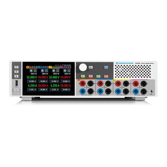
® Operating basics R&S NGP800 Display overview 5 Operating basics 5.1 Display overview The following displays the home window of R&S NGP800. It shows the output voltage and current level, status bar information and control settings of the instrument. Figure 5-1: Home window of R&S NGP800 with 4 channels Device status bar Channel status bar Channel display area... - Page 33 ® Operating basics R&S NGP800 Display overview Function Description If touch input is disabled, the icon is displayed and Touchscreen highlighted in yellow. Chapter 5.3.1.3, "User key", on page 43. If a SCPI command is received successfully, the SCPI command icon blinks once in white.
- Page 34 ® Operating basics R&S NGP800 Display overview Function Description If enabled, the icon is highlighted in white. If triggered, the icon blinks. Chapter 6.4.1, "Overcurrent protection (OCP)", on page 55. If enabled, the icon is highlighted in white. If triggered, the icon blinks. Chapter 6.4.2, "Overvoltage protection (OVP)", on page 55.
-
Page 35: Channel Display Area
® Operating basics R&S NGP800 Display overview 5.1.2 Channel display area The R&S NGP800 displays four channels display area (Ch 1, Ch 2, Ch 3, Ch 4) for R&S NGP804, R&S NGP824, R&S NGP814 and two channels display area (Ch 1, Ch 2) for R&S NGP802, R&S NGP822. -
Page 36: Using The Touchscreen
® Operating basics R&S NGP800 Using the touchscreen Figure 5-3: Color coding of difference operating conditions Color Operating mode Description OFF mode Output is OFF Editing mode A solid blue cursor is shown when an item is selected. CV mode Active outputs are operated in a constant voltage mode. -
Page 37: Accessing Functionality In The Home Window
® Operating basics R&S NGP800 Using the touchscreen 5.2.2 Accessing functionality in the home window The following illustrates various ways of accessing functions in the home window. 5.2.2.1 Settings button The "Settings" button navigates to the device/channel menu window where you can set device or individual channel settings on the instrument. -
Page 38: Voltage And Current Inputs
® Operating basics R&S NGP800 Using the touchscreen 5.2.2.2 Voltage and current inputs You can directly change the voltage and current level in the respective channel display area. 1. Select the voltage or current field in the channel display area to set value. The R&S NGP800 displays the on-screen keypad to enter value. -
Page 39: Input Data
® Operating basics R&S NGP800 Using the touchscreen Figure 5-6: Display of channel overview window 1 = Minimum, maximum and average values for power, voltage and current 2 = Calculation of energy result 3 = Number of samples collected 4 = Channel display area of selected channel 5 = Digital I/O trigger of selected channel 5.2.3 Input data The R&S NGP800 provides an on-screen keypad for you to enter numerical values. -
Page 40: Front Panel Keys
® Operating basics R&S NGP800 Front panel keys 2. Select "&123" or "ABC" key to switch between alphabet and numeric input data. Figure 5-8: Alphanumeric input data 5.3 Front panel keys For an overview of the front panel keys, see Figure 4-2. - Page 41 ® Operating basics R&S NGP800 Front panel keys 1. Press [Home] key. The R&S NGP800 displays the home window. 2. Select the "Settings" button on the required channel display area. Alternatively, press [Settings] key. 3. Select the "Device" tab to access the device menu. Figure 5-9: Device menu Menu Description...
- Page 42 ® Operating basics R&S NGP800 Front panel keys Menu Description "CSV Settings" Configures the file formatting for CSV file. "Data & Time" Configures date, time and clock format of the instrument. "Appearance" Configures brightness level for screen display and frontpanel keys.
-
Page 43: User Key
® Operating basics R&S NGP800 Front panel keys Menus Description "Arbitrary" Configures the arbitrary sequence, sequence repeatability response and the sequence ending behavior. "Ramp" Configures the ramping time applied on the channel output. "Overcurrent Protection (OCP)" Configures OCP protection settings ("Blowing Delay", "Initial Delay"... -
Page 44: Output And Channel Controls
® R&S NGP800 Operating basics Output power auto ranging ● When pressed and rotated, the rotary knob navigates along the set voltage or cur- rent position in the home window [Back] key Using the [Back] key, you can do several things: ●... -
Page 45: Operation Modes
® Operating basics R&S NGP800 Operation modes Figure 5-11: Output performance graph According to the electrical basis formula for power (P) = current (I) x voltage (V), the following results for the maximum power per channel: ● R&S NGP802, R&S NGP822: 200 W per channel (400 W max for the combination of two channels) ●... - Page 46 ® Operating basics R&S NGP800 Operation modes Voltage regulation Figure 5-12: Current limit CC mode The current I corresponds to the current setting adjustable in the instrument. If I reaches I , the instrument switches to CC mode, i.e. the output current remains constant and limited to I even if the load increases.
-
Page 47: Instrument Functions
® Instrument functions R&S NGP800 Setting the channels voltage and current 6 Instrument functions 6.1 Setting the channels voltage and current The R&S NGP800 comes with the following instrument models: Models Channels R&S NGP802, R&S NGP822 Ch 1, Ch 2 R&S NGP804, R&S NGP824, R&S NGP814 Ch 1, Ch 2, Ch 3, Ch 4 Toggle the respective channel key ([Ch 1], [Ch 2], [Ch 3], [Ch 4] ) on the front panel to... -
Page 48: Activating The Channels Output
® Instrument functions R&S NGP800 Activating the Channels output 4. Confirm value with the unit key (V/mV or A/mA). 5. Press the required channel key ([Ch 1], [Ch 2], [Ch 3] or [Ch 4]) on the front panel. The selected channel key is illuminated. See Figure 6-1. -
Page 49: Output
® Instrument functions R&S NGP800 Activating the Channels output Multiple outputs can be turned on or off at the same time. Figure 6-3: Output channels in different operating modes 6.2.1 Output The "Output" menu provides the settings for output delay, remote sensing, high impe-... - Page 50 ® Instrument functions R&S NGP800 Activating the Channels output The R&S NGP800 displays the "Output Delay" dialog. Figure 6-5: Output delay dialog 2. Set the required value. The R&S NGP800 displays the onscreen keypad for entry. 3. Confirm value with the unit keys. The output delay is the time between the "Output On"...
-
Page 51: Remote Sensing
® Instrument functions R&S NGP800 Activating the Channels output Figure 6-7: Delay text at channel display area 6.2.1.2 Remote sensing For voltage setting < 1 V, setting of remote sensing mode to "EXT" is recommended. The "Remote sensing" is a mechanism used to monitor and compensate the voltage drops on the cables connected to the load. -
Page 52: High Impedance Mode
® Instrument functions R&S NGP800 Activating the Channels output lated voltage output from the R&S NGP800. The voltage sensing relay remains switched on even when output is turned off. ● AUTO : The detection and enabling of the voltage sense relay automatically kicks in when the connection of remote sensing wires (S+, S- ) to the input of the load is applied. -
Page 53: Analog Input
® Instrument functions R&S NGP800 Analog input Slew rate control ● The slew rate control does not affect the output turn-on slew rate programmed via EasyRamp function. ● The slew rate control mode is not compatible with Analog Input QiuckArb func- tions. -
Page 54: Protection
® Instrument functions R&S NGP800 Protection Figure 6-9: Analog input dialog 4. Select the required type to regulate the channel output setting. The R&S NGP800 displays the "Select Analog Input Type" dialog. Figure 6-10: Select analog input type dialog 5. Activate the "Enabled" menu item. The R&S NGP800 enables the "Analog in"... -
Page 55: Overcurrent Protection (Ocp)
® Instrument functions R&S NGP800 Protection The R&S NGP800 displays the selected channel menu. 6.4.1 Overcurrent protection (OCP) When the drawn current exceeds the limit set for the respective channels, an alert is triggered and the affected channels are turned off according to the settings configured in the OCP dialog. -
Page 56: Overpower Protection (Opp)
® Instrument functions R&S NGP800 Protection When the output voltage exceeds the limit set for the respective channel, an alert is triggered and the affected channel is turned off according to the settings configured in the OVP dialog. 1. Select "Overvoltage Protection (OVP)" from the menu. The R&S NGP800 displays the OVP dialog. -
Page 57: Safety Limits
® Instrument functions R&S NGP800 Protection Figure 6-13: Overpower protection dialog 2. Activate the "Enabled" menu item. The R&S NGP800 enables the OPP and displays the "Overpower Protection (OPP)" icon on the selected channel status bar information. 3. Set the required level for OPP. The R&S NGP800 displays the on-screen keypad to set the value. -
Page 58: Tracking Function
® Instrument functions R&S NGP800 Tracking function Figure 6-14: Safety limits dialog 2. Activate the "Enabled" menu item. The R&S NGP800 limits the set voltage and current level and displays the "Safety Limits" icon on the selected channel status bar information. 3. -
Page 59: Digital Trigger I/O
® Instrument functions R&S NGP800 Digital trigger I/O Figure 6-15: Tracking dialog 3. Activate the "Enabled" menu item to enable the tracking function. 4. Set the required channels to be tracked. The R&S NGP800 tracks the voltage and/or current values to the selected tracked channels. - Page 60 ® Instrument functions R&S NGP800 Digital trigger I/O The data lines of the digital I/O interface output an "Active High" or "Active Low" signal when the trigger condition of the selected channel ("Ch 1", "Ch 2", "Ch 3", "Ch 4") is met. Table 6-1: Trigger in parameters and conditions Trigger in Trigger conditions...
- Page 61 ® Instrument functions R&S NGP800 Digital trigger I/O Table 6-2: Trigger out parameters and conditions Trigger out Trigger conditions Description parameters Channel "--", "Ch 1", "Ch 2", "Ch 3", "Ch 4" Output channel selected to monitor for trig- ger conditions. If "--"...
- Page 62 ® Instrument functions R&S NGP800 Digital trigger I/O Figure 6-16: DIO trigger block diagram 1. Press [Settings] key. The R&S NGP800 displays the device/channel menu window. 2. Select the device tab to configure digital I/O trigger. The R&S NGP800 displays the "Digital Trigger Menu" dialog. Figure 6-17: Digital trigger menu 3.
-
Page 63: Advanced Features
® Instrument functions R&S NGP800 Advanced features Figure 6-18: Digital trigger settings for pin 1 5. Set the required pin "Direction". Depending on the pin direction, different operating modes are available for trigger settings. Table 6-1 Table 6-2. 6. Set the required "Active Level " and "Channel" settings. 7. - Page 64 ® Instrument functions R&S NGP800 Advanced features The R&S NGP800 displays the device/channel menu window. 2. Select the required channel tab to configure QuickArb function. The R&S NGP800 displays the selected channel menu. 3. Select "Arbitrary" from the menu. The R&S NGP800 displays the "Arbitrary" dialog. Figure 6-19: Arbitrary dialog 4.
- Page 65 ® Instrument functions R&S NGP800 Advanced features – "Off": Output of the selected channel is turned off after performing the QuickArb function. – "Hold": Last voltage and current values output at the instrument. 10. Select [Back] key to return to channel menu dialog. 11.
-
Page 66: Easyramp
® Instrument functions R&S NGP800 Advanced features ● "Off": The output of the selected channel is turned off after performing the QuickArb function. ● "Hold": The last voltage and current values remains at the output terminal of the instrument. 7. Select (existing file) or (new file) to save the arbitrary data. -
Page 67: User Key
® Instrument functions R&S NGP800 User key Figure 6-24: Ramp dialog 4. Activate the "Enabled" menu item. The R&S NGP800 enables the EasyRamp function and displays the "Ramp" icon on the selected channel status bar information. 5. Set the required "Ramp Time". The R&S NGP800 displays the on-screen keypad to set the value. -
Page 68: Screenshot
® Instrument functions R&S NGP800 Screenshot Figure 6-25: User button action 4. Select the "User Button Action" to configure the user action. The R&S NGP800 displays a dialog to configure the user action. 5. Select the required user action. ● "Screenshot": Capture the current screen image of the instrument ●... -
Page 69: Data Logging
® Instrument functions R&S NGP800 Data logging Figure 6-26: Screenshot dialog 4. Select the "Save Location" to configure the screenshot file location. ● "Auto": Target folder is set to default file location: – With USB stick detected: /USB1A/NGP/screenshot for R&S NGP models –... - Page 70 ® Instrument functions R&S NGP800 Data logging Figure 6-27: Logging dialog 4. Select the "Target Folder" menu item to select the predefined target folder for data logger. If no USB stick is detected, "Target Folder" is set to internal memory ("int") partition. By default, "USB1A"...
-
Page 71: Csv Settings
® Instrument functions R&S NGP800 CSV settings 9. Configure the "CSV Settings". Chapter 6.11, "CSV settings", on page 71. 6.11 CSV settings A CSV file stores tabular data (numbers and text) in plain text. Each line of the file is a data record and each record consists of one or more fields, separated by a file delim- iter. -
Page 72: Graphical View Window
® Instrument functions R&S NGP800 Graphical view window Figure 6-30: CSV settings dialog 2. Set the required CSV parameters. The R&S NGP800 displays the respective dialog to set the CSV parameters. Table 6-3. 3. Select "Set" to confirm the value. Table 6-3: CSV settings CSV settings Selective fields in the dialog... - Page 73 ® Instrument functions R&S NGP800 Graphical view window Figure 6-31: Graphical view window 1 = Display window for measurement 2 = Time axis scale fixed at 5 s/div 3 = Configuration slot for measurement 4 = Reset measurements in display window 5 = Zero-origin of the graph 6 = Time axis 7 = Measurement axis...
- Page 74 ® Instrument functions R&S NGP800 Graphical view window Figure 6-32: Device menu 3. Select any of the configuration slots to configure the measurement parameters. The R&S NGP800 displays the configuration dialog. Figure 6-33: Configuration dialog 4. Select the available "Data Source" for configuration. The dimmed "Data Source"...
-
Page 75: File Manager
® Instrument functions R&S NGP800 File manager Figure 6-34: Display of minimum and maximum value of selected data source 8. Select "Apply" to confirm the configuration. 9. Select "Close" to exit configuration dialog. 6.13 File manager The "File Manager" provides file transfer functions between USB stick and internal memory of the instrument. -
Page 76: Store And Recall
® Instrument functions R&S NGP800 Store and recall 5. Select the required action in the file manager dialog. Table 6-4. 6. To view the selected file information, long-press on the selected filename in the file manager dialog. A pop-up message box is displayed with the file information. Figure 6-36: File information Table 6-4: File manager action Action... - Page 77 ® Instrument functions R&S NGP800 Store and recall ● Data Logging settings 1. Press [Settings] key. The R&S NGP800 displays the device/channel menu window. 2. Select the "Device" tab to configure file settings for store and recall function. The R&S NGP800 displays the device menu. 3.
- Page 78 ® Instrument functions R&S NGP800 Store and recall Figure 6-38: Factory reset - default settings message 2. Select "Yes" to overwrite instrument settings to default. The R&S NGP800 resets current instrument settings to default. 3. The R&S NGP800 displays a popup message to show that all settings reset to default.
-
Page 79: Interfaces
® Instrument functions R&S NGP800 Interfaces Select "Yes" to remove all files (arbitrary, logging, screenshots, settings) except the files in the documentation folder under the /int directory. 6.15 Interfaces There are various of ways how the R&S NGP800 can be remotely accessed and con- trolled. -
Page 80: Lan Connection
® Instrument functions R&S NGP800 Interfaces ● Wireless LAN 1. Select "Network" from the Figure 6-42. The R&S NGP800 displays the "Network" dialog. Figure 6-43: Network dialog 2. Set the required "SCPI Raw Port" and "Hostname". The R&S NGP800 displays the on-screen keypad to enter the port number and hostname. - Page 81 ® Instrument functions R&S NGP800 Interfaces To establish a network connection, connect a commercial RJ-45 cable to the LAN port of the instrument and to a PC or network switch. Depending on the network capacities, the TCP/IP address information for the instru- ment can be obtained in different ways.
-
Page 82: Wireless Lan Connection
® Instrument functions R&S NGP800 Interfaces ● "ON": Enables DHCP for automatic network parameter distribution and shows the values of the IP Address. By default, the instrument is configured to use dynamic configuration and obtain all address information automatically. ● "OFF": If the network does not support dynamic host configuration protocol (DHCP). - Page 83 ® Instrument functions R&S NGP800 Interfaces Instrument option R&S NGP-K102 (P/N: 5601.6400.03) option is required to connect the R&S NGP800 to a network via wireless LAN connection. Wireless LAN option is only available for instrument with serial number below 110000. An alterative to connection in local area network is wireless LAN connection.
-
Page 84: Vnc
® Instrument functions R&S NGP800 Interfaces Figure 6-47: WLAN connected 4. To disconnect, select the "Disconnect" in the "Wireless LAN settings" dialog. 6.15.2 VNC Using a VNC client tool on a computer, you can control the R&S NGP800 remotely. Alternatively, you can remote access the instrument webpage by using the IP address or hostname in a web browser. - Page 85 ® Instrument functions R&S NGP800 Interfaces 3. Set "Enabled" to "On" to enable VNC connection. 4. On the VNC client tool, connect to R&S NGP800 using the device IP address and VNC port number. If connected successfully, the NGP800 VNC interface is dis- played in the VNC client tool.
-
Page 86: Ftp
® Instrument functions R&S NGP800 Interfaces ● "Network Settings": Displays IPv4 configurations and settings dialog. The "Advanced IP configuration" provides setting to enable or disable the "ICMP Ping" service and "mDNS and DNS-SD" service. Click "Submit" to send changes to the instrument. ●... - Page 87 ® Instrument functions R&S NGP800 Interfaces 3. Set "Enabled" to "On" to enable FTP access. 4. Run the FTP client of your preference and key in the username, password, device IP or hostname and FTP port (default port number: 21) in your FTP client. Some FTP clients (File Explorer, Internet Explorer, etc.) allow connection via a URL- address.
-
Page 88: Usb Connection
® Instrument functions R&S NGP800 Interfaces 6.15.4 USB connection Change of USB class If a change in "USB Class" is detected (i.e. from "TMC" to "CDC" or vice versa), the rebooting of instrument is necessary to load the correct USB driver. ●... -
Page 89: General Instrument Settings
® Instrument functions R&S NGP800 General instrument settings The GPIB interface, sometimes called the General Purpose Interface Bus (GPIB), is a general purpose digital interface system that can be used to transfer data between two or more devices. Some of its key features are: ●... -
Page 90: Licenses Management
® Instrument functions R&S NGP800 General instrument settings 1. Press [Settings] key. The R&S NGP800 displays the device/channel menu window. 2. Select the "Device" tab. The R&S NGP800 displays the device menu. 6.16.1 Licenses management Options are enabled by entering a registered license key code. You may choose to install from an XML file on USB or by manually entering the key code. -
Page 91: Appearance Settings
® Instrument functions R&S NGP800 General instrument settings Figure 6-58: License key on-screen keyboard 2. Enter the key code (30-digit number) of the option in the entry box. 3. Confirm entries with the enter key If the correct key code is entered, the R&S NGP800 popup a message "Devicekey is installed"... -
Page 92: Sound Settings
® Instrument functions R&S NGP800 General instrument settings Figure 6-59: Appearance dialog 6.16.3 Sound settings 1. Select the "Sound Settings" to set sound settings. The R&S NGP800 displays the sound settings dialog. Figure 6-60: Sound settings dialog 2. Select the required fields to set alert. ●... -
Page 93: Date And Time
® Instrument functions R&S NGP800 General instrument settings 6.16.4 Date and time The time is regarded as UTC. There is no timezone selectable. 1. Select the "Date & Time" to set date and time format. The R&S NGP800 displays the date and time dialog. Figure 6-61: Date and time setting dialog 2. -
Page 94: Update Device
® Instrument functions R&S NGP800 General instrument settings Figure 6-62: Device information dialog Device information Description Model Model of the instrument. Instrument orderable part number. Serial No. Unique identification number for the instrument. Version Software version that is installed in the instrument. Hardware IDs Unique serial number of the front and channel boards of the instrument. -
Page 95: Adjustment
® Instrument functions R&S NGP800 Adjustment Figure 6-63: Update device dialog 2. Select the source and file location to update instrument firmware. 3. Select "UPDATE" to update the instrument firmware. The R&S NGP800 updates the instrument firmware accordingly. 6.17 Adjustment Adjustment shall be done at ambient temperature of 25 °C ±... -
Page 96: Analog In Adjustment
® Instrument functions R&S NGP800 Adjustment 6.17.1 Analog In adjustment The "Analog In Adjustment" adjusts the output channel voltage and current when a 0 V to 5 V is applied at the analog input of the terminal block, see "Digital I/O & analog input connector (14)"... - Page 97 ® Instrument functions R&S NGP800 Adjustment Figure 6-65: Adjustment -Analog In dialog 2. To overwrite user adjustment, select "Restore Factory Adjustment" to restore the analog in factory settings. Figure 6-66: Restore analog in factor adjustment message Select "Yes" to restore factory adjustment. 3.
- Page 98 ® Instrument functions R&S NGP800 Adjustment 4. Setup the adjustment with instruments illustrated in Figure 6-64. 5. Follow the on-screen instructions displayed in the Figure 6-67. Supply the required voltage to the analog input and key in the measured value from DMM using the on-screen keypad.
-
Page 99: Channel Adjustment
® Instrument functions R&S NGP800 Adjustment 6.17.2 Channel adjustment The "Adjustment" calculates the required adjustment coefficient internally for voltage and current on the selected channel. Channel adjustment setup Recommended instruments ● Digital multimeter (DMM): 6 ½ digits ● Shunt resistor: 10 mΩ, at least 25 A rating, 0.02 % accuracy, ●... - Page 100 ® Instrument functions R&S NGP800 Adjustment Figure 6-72: Current adjustment setup 1. Select the desired channel tab to perform the required channel adjustment proce- dures. The R&S NGP800 displays the selected channel adjustment dialog. Figure 6-73: Adjustment dialog 2. To overwrite user adjustment, select "Restore Factory Adjustment" to restore the channel factory settings.
- Page 101 ® Instrument functions R&S NGP800 Adjustment Figure 6-74: Restore channel factory adjustment message Select "Yes" to restore factory adjustment. 3. To proceed channel adjustment, select "User Adjustment" in Figure 6-73. The R&S NGP800 displays the "ADJUSTMENT" wizard to guide the channel adjustment procedures.
- Page 102 ® Instrument functions R&S NGP800 Adjustment Figure 6-76: Channel adjustment procedure 6. Confirm the entry with 7. Leave the setup connections as open. Select "Proceed" to start the voltage adjustment automatically. 8. Follow the on-screen instructions for current adjustment. 9. If adjustment is successful, the R&S NGP800 displays a message to indicate that the adjustment is successful.
-
Page 103: Remote Control Commands
This chapter provides the description of all remote commands available for the R&S NGP800 series. The commands are sorted according to the menu structure of the instrument. A list of commands in alphabetical order is given in the "List of Commands"... - Page 104 ® Remote control commands R&S NGP800 Common setting commands Parameters: <Value> Range: 0 to 255 *ESR? Event status read Returns the contents of the event status register in decimal form and then sets the reg- ister to zero. Return values: <Contents>...
- Page 105 ® Remote control commands R&S NGP800 Common setting commands Usage: Setting only *SRE <Contents> Service request enable Sets the service request enable register to the indicated value. This command deter- mines under which conditions a service request is triggered. Parameters: <Contents>...
-
Page 106: System Settings Commands
® Remote control commands R&S NGP800 System settings commands Stores the current instrument settings under the specified number in an internal mem- ory. The settings can be recalled using the command with the associated num- *RCL ber. Parameters: <Number> Range: 0..9 *RCL <Number>... -
Page 107: System:beeper:current:state 1
® Remote control commands R&S NGP800 System settings commands ....................112 SYSTem:TOUCh[:STATe] ...................... 112 SYSTem:VNC:PORT ...................... 112 SYSTem:VNC:STATe ......................112 SYSTem:UPTime? SYSTem:BEEPer:CURRent:STATe <arg0> Sets or queries "current control" beeper tone state. Parameters: <mode> Control beeper is activated. Control beeper is deactivated. Example: SYSTem:BEEPer:CURRent:STATe 1 The "CC-Mode Continuous Beep"... -
Page 108: System:beeper:warning:state
® Remote control commands R&S NGP800 System settings commands Usage: Event SYSTem:BEEPer:WARNing:STATe <arg0> Sets or queries "error/warning" beeper tone state. Parameters: <state> Beep sound for "error/warning" is enabled. Beep sound for "error/warning" is disabled. SYSTem:BEEPer:WARNing[:IMMediate] Returns a single "error/warning" beep immediately. Usage: Event SYSTem:COMMunicate:SOCKet:APPLy... -
Page 109: System:communicate:socket:ipaddress
® Remote control commands R&S NGP800 System settings commands Example: SYSTem:COMMunicate:SOCKet:GATeway? Return gateway address from LAN. SYSTem:COMMunicate:SOCKet:IPADdress <arg0> Sets or queries IP address of the LAN interface. Parameters: <address> IP address. Example: SYSTem:COMMunicate:SOCKet:IPADdress "192.168.1.128" Set IP address 192.168.1.128 for the LAN interface. SYSTem:COMMunicate:SOCKet:MASK <arg0>... -
Page 110: System:communicate:wlan:password
® Remote control commands R&S NGP800 System settings commands Options: R&S NGP-K102 Instrument with serial number below 110000 SYSTem:COMMunicate:WLAN:PASSword <arg0> Sets or queries password for WLAN. Parameters: <password> WLAN password. Example: SYSTem:COMMunicate:WLAN:PASSword? Return WLAN password. Usage: Setting only Options: R&S NGP-K102 Instrument with serial number below 110000 SYSTem:COMMunicate:WLAN:SSID <arg0>... -
Page 111: System:key:brightness 1.0
® Remote control commands R&S NGP800 System settings commands Example: SYSTem:DATE 2018, 10, 15 SYSTem:DATE? -> 2018, 10, 15 Returns the system date. SYSTem:KEY:BRIGhtness <brightness> Sets or queries the front panel key brightness. Parameters: <brightness> Sets the key brightness. Range: 0.0 to 1.0 Increment: 0.1 *RST:... -
Page 112: System:time
® Remote control commands R&S NGP800 System settings commands Usage: Event SYSTem:TIME <hh>, <mm>, <ss> Sets or queries the system time. Parameters: <hh> Sets the hours of the system time. <mm> Sets the minutes of the system time. <ss> Sets the seconds of the system time. SYSTem:TIME 12, 30, 59 Example: SYSTem:TIME? ->... -
Page 113: Display Commands
® Remote control commands R&S NGP800 Trigger commands 7.3 Display commands The DISPlay subsystem contains the commands for display functions, which do not affect signal generation directly....................... 113 DISPlay:BRIGhtness ..................113 DISPlay[:WINDow]:TEXT:CLEar ..................113 DISPlay[:WINDow]:TEXT[:DATA] DISPlay:BRIGhtness <brightness> DISPlay:BRIGhtness? Sets or queries the display brightness. Parameters: <brightness>... - Page 114 ® Remote control commands R&S NGP800 Trigger commands TRIGger:CHANnel:DIO<IO> <arg0> Suffix: <IO> 1..8 Parameters: <channel> NONE | CH1 | CH2 | CH3 | CH4 | ALL NONE No channel is set as the trigger channel. Ch 1 is set as the trigger channel. Ch 2 is set as the trigger channel.
- Page 115 ® Remote control commands R&S NGP800 Trigger commands VMODe Output the selected logic level when the selected channel oper- ates in the CV mode. CMODe Output the selected logic level when the selected channel oper- ates in the CC mode. VLEVel Output the selected logic level when the voltage level of the selected channel is greater or equal to the set voltage level, i.e.
- Page 116 ® Remote control commands R&S NGP800 Trigger commands For output mode - output the selected logic level when logging is enabled. For input mode - Logging is enabled when the selected logic level is met. PLEVel Output the selected logic level when the power level of the selected channel is greater or equal to the set power level, i.e.
-
Page 117: Configuration Commands
® Remote control commands R&S NGP800 Configuration commands TRIGger[:ENABle]:GENeral <arg0> Sets or queries the enable state of the master on/off of Digital I/O trigger. Parameters: <master_state> Master state of Digital I/O trigger is enabled. Master state of Digital I/O trigger is disabled. *RST: TRIGger[:ENABle]:SELect:DIO<IO>... - Page 118 ® Remote control commands R&S NGP800 Configuration commands Example: Selecting a channel You can select a channel either with an OUTput parameter, or just by the channel number. This example lists all ways how you can select and query a selected channel. // ************************************************ // Select a channel // ************************************************...
-
Page 119: Safety Limit Setting
® Remote control commands R&S NGP800 Configuration commands Example: Example "Selecting a channel" on page 118. 7.5.2 Safety limit setting The SOURce:ALIM subsystem contains the commands for setting the safety limits of the output channels. Example: Configuring the safety limit This example contains all commands to configure and query the voltage and current safety limit. - Page 120 ® Remote control commands R&S NGP800 Configuration commands ....................120 [SOURce:]ALIMit[:STATe] ............. 120 [SOURce:]VOLTage[:LEVel][:IMMediate]:ALIMit:LOWer ............ 121 [SOURce:]VOLTage[:LEVel][:IMMediate]:ALIMit[:UPPer] .............121 [SOURce:]CURRent[:LEVel][:IMMediate]:ALIMit:LOWer ............122 [SOURce:]CURRent[:LEVel][:IMMediate]:ALIMit[:UPPer] [SOURce:]ALIMit[:STATe] <arg0>[, <Channel list>] [SOURce:]ALIMit[:STATe]? [<Channel list>] Sets or queries the safety limit state. Parameters: <state> Activates the safety limit. Deactivates the safety limit.
- Page 121 ® Remote control commands R&S NGP800 Configuration commands [SOURce:]VOLTage[:LEVel][:IMMediate]:ALIMit[:UPPer] <New value for voltage> [SOURce:]VOLTage[:LEVel][:IMMediate]:ALIMit[:UPPer]? [<Channel list>] Sets or queries the upper safety limit for voltage. Setting parameters: <voltage> <numeric value> | MIN | MINimum | MAX | MAXimum <numeric value> Numeric value for upper safety limit.
-
Page 122: Remote Sense Setting
® Remote control commands R&S NGP800 Configuration commands [SOURce:]CURRent[:LEVel][:IMMediate]:ALIMit[:UPPer] <New value for current>[, <Channel list>] [SOURce:]CURRent[:LEVel][:IMMediate]:ALIMit[:UPPer]? [<Channel list>] Sets or queries the upper safety limit for current. Setting parameters: <current> <numeric value> | MIN | MINimum | MAX | MAXimum <numeric value>... -
Page 123: Voltage Setting
® Remote control commands R&S NGP800 Configuration commands If remote sense detection is set "EXT", internal voltage sense relay in the instrument is switched on and the connection of remote sense wires (S+, S- ) to the input of the load become necessary. - Page 124 ® Remote control commands R&S NGP800 Configuration commands Example: Configuring the output voltage This example contains all commands to configure and query the output voltage. // ************************************************ // Select the channel // ************************************************ INST OUT1 // ************************************************ // Set upper or lower voltage safety limit // ************************************************ //sets the safety limits to enable ALIM 1...
- Page 125 ® Remote control commands R&S NGP800 Configuration commands INST OUT1 VOLT:STEP 4 VOLT UP // decreases the voltage in the selected channel // from 4 Volts VOLT DOWN // queries the voltage step size VOLT:STEP? // response: "4.000" ............125 [SOURce:]VOLTage[:LEVel][:IMMediate][:AMPLitude] ..........126 [SOURce:]VOLTage[:LEVel][:IMMediate]:STEP[:INCRement]...
-
Page 126: Current Setting
® Remote control commands R&S NGP800 Configuration commands [SOURce:]VOLTage[:LEVel][:IMMediate]:STEP[:INCRement] <desired stepsize>[, <Optional default step query>] [SOURce:]VOLTage[:LEVel][:IMMediate]:STEP[:INCRement]? [<Optional default step query>] Sets or queries the incremental step size for the command. VOLT UP | VOLT DOWN Setting parameters: <stepsize> <numeric value> | DEF | DEFault <numeric value>... - Page 127 ® Remote control commands R&S NGP800 Configuration commands Example: Configuring the current output // ************************************************ // Select the channel // ************************************************ INST OUT1 // ************************************************ // Set upper or lower current safety limit // ************************************************ //sets the safety limits to enable ALIM 1 //queries the safety limits state ALIM?
- Page 128 ® Remote control commands R&S NGP800 Configuration commands CURR UP // queries the current step size CURR:STEP? // response: 1.0000 ............128 [SOURce:]CURRent[:LEVel][:IMMediate][:AMPLitude] ..........129 [SOURce:]CURRent[:LEVel][:IMMediate]:STEP[:INCRement] [SOURce:]CURRent[:LEVel][:IMMediate][:AMPLitude] <New value for current>[, <Channel list>] [SOURce:]CURRent[:LEVel][:IMMediate][:AMPLitude]? [<Channel list>] Sets or queries the current value of the selected channel. Parameters: <current>...
-
Page 129: Combined Setting Of Voltage And Current Settings
® Remote control commands R&S NGP800 Configuration commands [SOURce:]CURRent[:LEVel][:IMMediate]:STEP[:INCRement] <desired stepsize>[, <Optional default step query>] [SOURce:]CURRent[:LEVel][:IMMediate]:STEP[:INCRement]? [<Optional default step query>] Sets or queries the incremental step size for the command. CURR UP | CURR DOWN Setting parameters: <stepsize> <numeric value> | DEF | DEFault <numeric value>... -
Page 130: Output Setting
® Remote control commands R&S NGP800 Configuration commands MAX | MAXimum Max value for voltage at 64.050V. DEF | DEFault Default voltage. *RST: 1.000 Default unit: V <current> numeric | MIN | MINimum | MAX | MAXimum | DEF | DEFault numeric Numeric value for current in the range of 0.000 to 20.0100. - Page 131 ® Remote control commands R&S NGP800 Configuration commands Example: Activating the channels You can activate a selected channel and turn on or off the outputs either individually or all outputs simultaneously. This example lists all ways how you can activate and query the outputs.
- Page 132 ® Remote control commands R&S NGP800 Configuration commands Parameters for setting and query: <Channel list> <list> Example: OUTPut:SRATe 1 OUTPut:SRATe? -> 1 Returns reduce slew rate option as on. Example: OUTPut:SRATe? (@1) Returns reduce slew rate option at channel 1. OUTPut:IMPedance[:STATe] <arg0>[, <Channel list>] OUTPut:IMPedance[:STATe]? [<Channel list>] Sets or queries the output impedance state for the selected channel.
- Page 133 ® Remote control commands R&S NGP800 Configuration commands Switches on previous selected channels. Parameters for setting and query: <Channel list> <list> OUTP? (@1) Example: Queries the output state at channel 1. Example: Example "Activating the channels" on page 131. OUTPut:DELay:DURation <New value for sequence delay (selected channel)>[, <Channel list>] OUTPut:DELay:DURation? [<Channel list>] Sets or queries the duration for output delay.
-
Page 134: Ocp Setting
® Remote control commands R&S NGP800 Configuration commands Example: OUTPut:DELay 1 OUTPut:DELay? -> 1 Returns output delay state as on. Example: OUTPut:DELay? (@1) Returns output delay state at channel 1. OUTPut:SELect <arg0>[, <Channel list>] OUTPut:SELect? [<Channel list>] Sets or queries the output state of selected channel. Parameters: <state>... - Page 135 ® Remote control commands R&S NGP800 Configuration commands // ************************************************ // Set a delay time for the overcurrent protection. The delay time // takes effect when the channel output is turned on. // ************************************************ // sets 0.05 s delay for the overcurrent protection FUSE:DEL 0.05 // queries the currently set delay time of the overcurrent protection // in the selected channel...
- Page 136 ® Remote control commands R&S NGP800 Configuration commands FUSE:LINK 2 // queries the combined overcurrent protection of the selected channel FUSE:LINK? // ************************************************ // Unlink linked overcurrent protection // ************************************************ FUSE:UNLink 2 // queries the combined overcurrent protection of the selected channel FUSE:LINK? //response 0 ....................136...
- Page 137 ® Remote control commands R&S NGP800 Configuration commands Parameters for setting and query: <Channel list> <list> Example: FUSE:DEL:INIT? (@1) Queries initial fuse delay time at channel 1. Example: Example "Configuring fuses" on page 134. FUSE:DELay[:BLOWing] <New value for voltage>[, <Channel list>] FUSE:DELay[:BLOWing]? [<Channel list>] Sets the fuse delay time.
- Page 138 ® Remote control commands R&S NGP800 Configuration commands FUSE:TRIPped? [<Channel list>] FUSE:TRIPped?? [<Channel list>] Queries the OCP state of the selected channel. Parameters: <Channel list> <list> Example: FUSE:TRIP? Response 1, the OCP is tripped. Response 0, the OCP is not tripped. Example: FUSE:TRIP? (@1) Queries fuse tripped status at channel 1.
-
Page 139: Ovp Setting
® Remote control commands R&S NGP800 Configuration commands Example: FUSE? (@1) Queries fuse state at channel 1. 7.5.9 OVP setting The VOLTage:PROTection subsystem contains the commands for setting the over- voltage protection parameters for the output channels. The default unit is V. User Manual 5601.5610.02 ─... - Page 140 ® Remote control commands R&S NGP800 Configuration commands Example: Configuring the overvoltage protection // ************************************************ // Set the overvoltage protection value // ************************************************ INST OUT1 //activates the OVP of the previous selected channel VOLT:PROT 1 // selects a channel and sets the OVP VOLT:PROT:LEV 5 // queries the output overvoltage value of a channel VOLT:PROT:LEV?
- Page 141 ® Remote control commands R&S NGP800 Configuration commands ................. 141 [SOURce:]VOLTage:PROTection[:STATe] ................141 [SOURce:]VOLTage:PROTection:CLEar ................141 [SOURce:]VOLTage:PROTection:LEVel ..............142 [SOURce:]VOLTage:PROTection:TRIPped? [SOURce:]VOLTage:PROTection[:STATe] <En/Disable volt protection>[, <Channel list>] [SOURce:]VOLTage:PROTection[:STATe]? [<Channel list>] Sets or queries the OVP state of the previous selected channel. Parameters: <state>...
-
Page 142: Opp Setting
® Remote control commands R&S NGP800 Configuration commands <numeric value> Numeric value for the overvoltage protection value in V. MIN | MINimum Minimum value for the overvoltage protection value at 0.000 V. MAX | MAXimum Maximum value for the overvoltage protection value at 64.050 V. Range: 0.000 to 64.050 *RST:... - Page 143 ® Remote control commands R&S NGP800 Configuration commands Example: Configuring the overpower protection // ************************************************ // Set the overpower protection value // ************************************************ INST OUT1 //activates the OPP of the previous selected channel POW:PROT 1 // selects a channel and sets the OPP POW:PROT:LEV 5 // queries the output overvoltage value of a channel POW:PROT:LEV?
- Page 144 ® Remote control commands R&S NGP800 Configuration commands OPP is deactivated OPP is activated Parameters for setting and query: <Channel list> <list> Example: POW:PROT? (@1) Queries OPP state at channel 1. Example: Example "Configuring the overpower protection" on page 143. [SOURce:]POWer:PROTection:CLEar [<Channel list>] [SOURce:]POWer:PROTection:CLEar [<Channel list>] Resets the OPP state of the selected channel.
-
Page 145: Reset Protection Tripped State
® Remote control commands R&S NGP800 Configuration commands Parameters for setting and query: <Channel list> <list> Example: POW:PROT:LEV? (@1) Queries OPP value at channel 1. Example: Example "Configuring the overpower protection" on page 143. [SOURce:]POWer:PROTection:TRIPped? [<Channel list>] [SOURce:]POWer:PROTection:TRIPped?? [<Channel list>] Queries the OPP state of the selected channel. -
Page 146: Interface Setting
® Remote control commands R&S NGP800 Configuration commands TRACking[:ENABle]:CH<CHANNEL> <arg0> Sets or queries the tracking status on selected channel. Suffix: <CHANNEL> 1..4 Parameters: <arg0> Tracking is disabled on specified channel. Tracking is enabled on specified channel. TRACking[:ENABle]:GENeral <arg0> Sets or queries the status of the master tracking state. Parameters: <arg0>... -
Page 147: Measurement Commands
® Remote control commands R&S NGP800 Measurement commands USB TMC connection. 7.6 Measurement commands The MEASure subsystem provides commands to query the voltage and current values of a channel.......................... 147 READ? ..................147 MEASure[:SCALar]:ENERgy? .................148 MEASure[:SCALar]:ENERgy:RESet .................148 MEASure[:SCALar]:ENERgy:STATe ................148 MEASure[:SCALar]:STATistic:COUNt? ................ - Page 148 ® Remote control commands R&S NGP800 Measurement commands Example: MEAS:ENER? (@1) Queries the measured accumulated energy value at channel 1. Usage: Query only MEASure[:SCALar]:ENERgy:RESet [<Channel list>] MEASure[:SCALar]:ENERgy:RESet [<Channel list>] Resets the energy counter for the selected channel. Parameters: <Channel list> <list>...
- Page 149 ® Remote control commands R&S NGP800 Measurement commands MEASure[:SCALar]:STATistic:RESet [<Channel list>] MEASure[:SCALar]:STATistic:RESet [<Channel list>] Resets the minimum, maximum and average statistic values for voltage, current, and power. Additionally this command resets the measured energy. Parameters: <Channel list> <list> Example: MEAS:STAT:RES (@1) Resets all the statistic values at channel 1.
- Page 150 ® Remote control commands R&S NGP800 Measurement commands Usage: Query only MEASure[:SCALar]:CURRent[:DC]:MIN? [<Channel list>] MEASure[:SCALar]:CURRent[:DC]:MIN?? [<Channel list>] Queries the minimum measured output power. Parameters: <Channel list> <list> Example: MEAS:CURR:DC:MIN? (@1) Queries the minimum measured output current at channel 1. Usage: Query only MEASure[:SCALar]:CURRent[:DC]:STATistic? [<Channel list>] MEASure[:SCALar]:CURRent[:DC]:STATistic?? [<Channel list>]...
- Page 151 ® Remote control commands R&S NGP800 Measurement commands Usage: Query only MEASure[:SCALar]:POWer:MAX? [<Channel list>] MEASure[:SCALar]:POWer:MAX?? [<Channel list>] Queries the maximum measured output power. Parameters: <Channel list> <list> Example: MEAS:POW:MAX? (@1) Queries the maximum measured output power at channel 1. Usage: Query only MEASure[:SCALar]:POWer:MIN? [<Channel list>] MEASure[:SCALar]:POWer:MIN?? [<Channel list>]...
- Page 152 ® Remote control commands R&S NGP800 Measurement commands Usage: Query only MEASure[:SCALar][:VOLTage][:DC]:AVG? [<Channel list>] MEASure[:SCALar][:VOLTage][:DC]:AVG?? [<Channel list>] Queries the average measured output voltage. Parameters: <Channel list> <list> Example: MEAS:VOLT:AVG? (@1) Queries the average measured output voltage at channel 1. Usage: Query only MEASure[:SCALar][:VOLTage][:DC]:MAX? [<Channel list>] MEASure[:SCALar][:VOLTage][:DC]:MAX?? [<Channel list>]...
-
Page 153: Advanced Operating Commands
® Remote control commands R&S NGP800 Advanced operating commands 7.7 Advanced operating commands The following shows the subsystem that contains the commands for configuring the , QuickArb, EasyRamp, Analog Input Adjustment functions. 7.7.1 Arbitrary The ARBitrary subsystem contains the commands for configuring an arbitrary sequence for the output channels. - Page 154 ® Remote control commands R&S NGP800 Advanced operating commands ....................154 ARBitrary:BLOCk:CLEar ......................154 ARBitrary:BLOCk ....................154 ARBitrary:BLOCk:DATA ..................155 ARBitrary:BLOCk:ENDPoint? ....................155 ARBitrary:BLOCk:FNAMe ..................155 ARBitrary:BLOCk:REPetitions ......................156 ARBitrary[:STATe] ......................156 ARBitrary:CLEar ......................156 ARBitrary:DATA ..................157 ARBitrary:SEQuence:ENDPoint? ......................157 ARBitrary:FNAMe ......................157 ARBitrary:LOAD .....................158...
- Page 155 ® Remote control commands R&S NGP800 Advanced operating commands Parameters: <data> voltage1, current1, time1, interpolation mode1, voltage2, cur- rent2, time2, interpolation mode2, ... Voltage and current settings depending on the instrument type. If the interpolation mode is sets to 1, it indicates that the mode is activated.
- Page 156 ® Remote control commands R&S NGP800 Advanced operating commands Parameters: <repetitions> Repetition of the block of arbitrary data. Example: INST OUT1 ARB:BLOC 1 ARB:BLOC:REP 0 Set repetition of infinity to block 1 of Ch 1. ARBitrary[:STATe] <>[, <Channel list>] ARBitrary[:STATe]? [<Channel list>] Sets or queries the QuickArb function for the previous selected channel.
- Page 157 ® Remote control commands R&S NGP800 Advanced operating commands Parameters: <data> voltage1, current1, time1, interpolation mode1, voltage2, cur- rent2, time2, interpolation mode2, ... Voltage and current settings depending on the instrument type. If the interpolation mode is sets to 1, it indicates that the mode is activated.
- Page 158 ® Remote control commands R&S NGP800 Advanced operating commands Example: INST OUT1 ARB:DATA 10,1,0.5,0 ARB:REP 10 ARB:FNAM "ARB03.CSV",INT ARB:SAVE ARB:LOAD Loads an arbitrary data from filename ARB03.CSV. Usage: Event ARBitrary:REPetitions <> Sets or queries the repetition rate of the defined arbitrary waveform for the previous selected channel.
- Page 159 ® Remote control commands R&S NGP800 Advanced operating commands HOLD If the QuickArb function is finished, the last arbitrary point of the user-defined arbitrary list is held. *RST: Example: Example "Configuring an arbitrary sequence" on page 153. ARBitrary:SEQuence:CLEar Clears the arbitrary sequence. Usage: Event ARBitrary:SEQuence:REPetitions <>...
-
Page 160: Easyramp
® Remote control commands R&S NGP800 Advanced operating commands ARBitrary:TRIGgered:POINt[:STATe] <> Sets or queries the trigger condition of the arbitrary step point for the selected channel. Parameters: <condition> OFF | 1 | 2 | 3 | 4 | 5 | 6 | 7 | 8 There is no DIO pin that has a mode set to arbitrary step point for the selected channel. - Page 161 ® Remote control commands R&S NGP800 Advanced operating commands EasyRamp function is activated. *RST: Parameters for setting and query: <Channel list> <list> Example: INST OUT1 VOLT:RAMP ON VOLT:RAMP? -> 1 EasyRamp function of Ch1 is activated Example: VOLT:RAMP ON, (@1) VOLT:RAMP? (@1) Sets and queries the state of ramp function at channel 1.
-
Page 162: Analog Input
® Remote control commands R&S NGP800 Advanced operating commands 7.7.3 Analog input The VOTage:AINPut subsystem contains the commands for configuring the analog input..................162 [SOURce:]VOLTage:AINPut:INPut ...............162 [SOURce:]VOLTage:AINPut:TRIGgered[:STATe ] ................162 [SOURce:]VOLTage:AINPut[:STATe] [SOURce:]VOLTage:AINPut:INPut <arg0>[, <Channel list>] [SOURce:]VOLTage:AINPut:INPut? [<Channel list>] Sets or queries the analog input mode. Parameters: <input>... -
Page 163: Adjustment
® Remote control commands R&S NGP800 Advanced operating commands Analog input for selected channel is disabled. Parameters for setting and query: <Channel list> <list> VOLT:AINP? (@1) Example: Queries the analog input state at channel 1. 7.7.4 Adjustment The CALibration subsystem contains the commands for analog input and channel adjustment. -
Page 164: Calibration:ainput:data
® Remote control commands R&S NGP800 Advanced operating commands Usage: Query only CALibration:AINPut:DATA <arg0> Sets the analog input adjustment data. Parameters: <data> Measured value from DMM. CALibration:AINPut:DATE? Returns the analog input adjustment date ("DD-MM-YY"). Usage: Query only CALibration:AINPut:END Ends the analog input adjustment. Usage: Event CALibration:AINPut:FACTory:RESTore... -
Page 165: Calibration:ainput:umax
® Remote control commands R&S NGP800 Advanced operating commands State Descriptions 0-15 0x0 - 0xE ( 0x0000 - 0x1111) bit3|bit2|bit1|bit0 bit0 - pin 1 of analog input bit1 - pin 2 of analog input bit2 - pin 3 of analog input bit3 - pin 4 of analog input e.g. -
Page 166: Calibration:current:data
® Remote control commands R&S NGP800 Advanced operating commands CALibration:CURRent:DATA <arg0> Set the DMM reading after setting the output current level in channel adjustment proc- ess. Parameters: <current> Measured value from DMM. CALibration:CURRent:IMAX Sets the output current to high value 100 % of Imax during current adjustment. Usage: Event CALibration:CURRent:IMIN... -
Page 167: Calibration:temperature
® Remote control commands R&S NGP800 Advanced operating commands State Descriptions Idle Busy Waiting Voltage adjustment completed Current adjustment completed Successful channel adjustment Failed channel adjustment Example: CAL:STAT? -> 12 Voltage adjustment is successful. Usage: Query only CALibration:TEMPerature? Returns the temperature of selected channel. Usage: Query only CALibration:USER... -
Page 168: Data And File Management Commands
® Remote control commands R&S NGP800 Data and file management commands 7.8 Data and file management commands The DATA and HCOPy subsystem contains commands for managing the files in the instrument and external USB stick. The LOG subsystem contains the commands for managing the data logging of the instrument. -
Page 169: Data:delete
® Remote control commands R&S NGP800 Data and file management commands DATA:DELete <> Deletes the specified file from memory. Setting parameters: <filepath> Filepath of the file. Example: DATA:DEL "/int/logging/log-20201203T095013.965.csv" Deletes internal logging file 'log-20201203T095013.965.csv' Usage: Setting only DATA:LIST? Queries all files in internal memory ('/int/') and external memory ('/USB'). Example: DATA:LIST? ->... -
Page 170: Hcopy:size:y
® Remote control commands R&S NGP800 Data and file management commands Usage: Query only HCOPy:SIZE:Y? Returns the vertical dimension of the screenshots. Usage: Query only LOG[:STATe] <arg0> Sets or queries the data logging state. Parameters: <state> Data logging function is enabled. Data logging function is disabled. -
Page 171: Log:data
® Remote control commands R&S NGP800 Data and file management commands LOG:DATA? Returns 12 sets of latest logging data with minimum logging interval (8 ms). Depending on the models, the data is returned in the following format for a 2-channel models: <Ch1_voltage>, <Ch1_current>,<Ch1_power>,<Ch2_voltage>, <Ch2_cur- rent>,<Ch2_power>, <Ch1_voltage>, <Ch1_current>,<Ch1_power>, <Ch2_voltage>, <Ch2_current>,<Ch2_power>... -
Page 172: Log:interval
® Remote control commands R&S NGP800 Data and file management commands Example: LOG 0 LOG:FNAM? -> "" LOG 1 LOG:FNAM? -> "/int/logging/log-20190318T1141853.407.csv" Enables the data logging and queries the data log filename. LOG:INTerval <Set new value>[, <Return min or max>] LOG:INTerval? [<Return min or max>] Sets or queries the data logging measurement interval. -
Page 173: Log:triggered[:State ]
® Remote control commands R&S NGP800 Data and file management commands LOG:MODE <arg0> LOG:MODE? <arg0> Sets or queries the data logging mode. Parameters for setting and query: <mode> UNLimited | COUNt | DURation | SPAN UNLimited Infinite data capture. COUNt Number of measurement values to be captured. -
Page 174: Status Reporting Commands
® Remote control commands R&S NGP800 Status reporting commands 1 | 2 | 3 | 4 | 5 | 6 | 7 | 8 DIO pin/s are enabled with a mode set to logging. When DIO pin is enabled with logging mode, logging of the channel assigned to that pin will be enabled when the correct voltage is applied to the DIO pin. - Page 175 ® Remote control commands R&S NGP800 Status reporting commands STATus:OPERation:INSTrument:ENABle <arg0> STATus:OPERation:INSTrument:ISUMmary<Channel>:ENABle <arg0> Controls or queries the ENABle part of the STATus:OPERation register. The ENABle defines which events in the EVENt part of the status register are forwarded to the OPERation summary bit (bit 7) of the status byte.
-
Page 176: Status:questionable Registers
® Remote control commands R&S NGP800 Status reporting commands STATus:OPERation:INSTrument:PTRansition <arg0> STATus:OPERation:INSTrument:ISUMmary<Channel>:PTRansition <arg0> Sets or queries the positive transition filter. Setting a bit in the positive transition filter shall cause a 0 to 1 transition in the corresponding bit of the associated condition regis- ter to cause a 1 to be written in the associated bit of the corresponding event register. - Page 177 ® Remote control commands R&S NGP800 Status reporting commands STATus:QUEStionable:INSTrument:ENABle <arg0> STATus:QUEStionable:INSTrument:ISUMmary<Channel>:ENABle <arg0> Sets or queries the enable mask that allows true conditions in the EVENt part to be reported in the summary bit. If a bit in the ENABle part is 1, and the corresponding EVENt bit is true, a positive tran- sition occurs in the summary bit.
- Page 178 ® Remote control commands R&S NGP800 Status reporting commands STATus:QUEStionable:INSTrument:PTRansition <arg0> STATus:QUEStionable:INSTrument:ISUMmary<Channel>:PTRansition <arg0> Sets or queries the positive transition filter. Setting a bit in the positive transition filter shall cause a 0 to 1 transition in the corresponding bit of the associated condition regis- ter to cause a 1 to be written in the associated bit of the corresponding event register.
-
Page 179: Maintenance And Support
® Maintenance and support R&S NGP800 Maintenance 8 Maintenance and support 8.1 Maintenance Regular maintenance improves the life span of the instrument, the following chapter provides information on instrument maintenance. Cleaning Before cleaning the instrument, ensure that it has been switched off and the power cable is disconnected. -
Page 180: Contacting Customer Support
® Maintenance and support R&S NGP800 Contacting customer support 8.2 Contacting customer support Technical support – where and when you need it For quick, expert help with any Rohde & Schwarz product, contact our customer sup- port center. A team of highly qualified engineers provides support and works with you to find a solution to your query on any aspect of the operation, programming or applica- tions of Rohde &... -
Page 181: Annex
® Additional Basics on Remote Control R&S NGP800 Messages and command structure Annex A Additional Basics on Remote Control A.1 Messages and command structure A.1.1 Messages Instrument messages are employed in the same way for all interfaces, if not indicated otherwise in the description. -
Page 182: Scpi Command Structure
® Additional Basics on Remote Control R&S NGP800 Messages and command structure are device-specific, however, their syntax follows SCPI rules as permitted by the standard. Instrument responses Instrument responses (response messages and service requests) are messages which the instrument sends to the controller after a query. They can contain measurement results, instrument settings and information on the instrument status. - Page 183 ® Additional Basics on Remote Control R&S NGP800 Messages and command structure Syntax for device-specific commands For demonstration purposes only, assume the existence of the following commands for this section: ● MEASure:CURRent[:DC]? ● MEASure:VOLTage[:DC]? ● FUSE[:STATe] {0 | 1} ● FUSE[:STATe]? Long and short form The mnemonics feature a long form and a short form.
- Page 184 ® Additional Basics on Remote Control R&S NGP800 Messages and command structure Special characters Table A-2: Special characters A vertical stroke in parameter definition indicates alternative possibilities in the sense of "or". The effect of the command differs, depending on the used parameter. Example: ●...
- Page 185 ® Additional Basics on Remote Control R&S NGP800 Messages and command structure SCPI parameters Many commands are supplemented by a parameter or a list of parameters. The parameters must be separated from the header by a whitespace (ASCII code 0 to 9, 11 to 32 decimal, e.g.
- Page 186 ® Additional Basics on Remote Control R&S NGP800 Messages and command structure Example: OUTP:STAT ON OUTP:STAT? Response: 1 Text Text parameters observe the syntactic rules for key words, i.e. they can be entered using a short or long form. Like any parameter, they have to be separated from the header by a white space.
-
Page 187: Command Sequence And Synchronization
® Additional Basics on Remote Control R&S NGP800 Command sequence and synchronization An asterisk marks a common command. " Quotation marks introduce a string and terminate it. A whitespace (ASCII-Code 0 to 9, 11 to 32 decimal, e.g. blank) separates the header from the parameters. -
Page 188: Preventing Overlapping Execution
The controller can be forced to wait for the corre- sponding action. The R&S NGP800 series does not support parallel processing of remote commands. If OPC? returns a "1", the device is able to process new commands. - Page 189 ® Additional Basics on Remote Control R&S NGP800 Status reporting system Depending on the value of the read register, you can draw conclusions on the current status of the device. For example, when the unit operates in constant voltage, the result of the returned ISUM register is a decimal "2"...
- Page 190 ® Additional Basics on Remote Control R&S NGP800 Status reporting system CONDition ● The CONDition register queries the actual state of the instrument. If you want to query the constant voltage or current mode, you have to use the CONDition regis- ter.
- Page 191 ® Additional Basics on Remote Control R&S NGP800 Status reporting system Event Status Register (ESR) and Event Status Enable Register (ESE) The ESR is defined in IEEE 488.2. It can be compared with the EVENt part of a SCPI register. The event status register can be read out using the command *ESR?. The ESE corresponds to the ENABle part of a SCPI register.
- Page 192 ® Additional Basics on Remote Control R&S NGP800 Status reporting system Bit No. Meaning POWer (OPP Tripped) This bit is set if an over power protection has tripped. Temperature Overrange This bit is set if an over temperature occurs. 5 to 7 Not used CALibrating This bit is set when instrument is performing calibration.
- Page 193 ® Additional Basics on Remote Control R&S NGP800 Status reporting system Error Queue Each error state in the instrument leads to an entry in the error queue. The entries of the error queue are detailed plain text error messages. You can look them up in the error log or via remote control using SYSTem:ERRor[:NEXT]?.
-
Page 194: List Of Commands
® List of commands R&S NGP800 List of commands [SOURce:]ALIMit[:STATe]..........................120 [SOURce:]CURRent[:LEVel][:IMMediate]:ALIMit:LOWer................121 [SOURce:]CURRent[:LEVel][:IMMediate]:ALIMit[:UPPer]................122 [SOURce:]CURRent[:LEVel][:IMMediate]:STEP[:INCRement]..............129 [SOURce:]CURRent[:LEVel][:IMMediate][:AMPLitude]..................128 [SOURce:]POWer:PROTection:CLEar......................144 [SOURce:]POWer:PROTection:LEVel......................144 [SOURce:]POWer:PROTection:TRIPped?.....................145 [SOURce:]POWer:PROTection[:STATe]......................143 [SOURce:]PROTection:CLEar........................145 [SOURce:]VOLTage:AINPut:INPut.........................162 [SOURce:]VOLTage:AINPut:TRIGgered[:STATe ]..................162 [SOURce:]VOLTage:AINPut[:STATe]......................162 [SOURce:]VOLTage:PROTection:CLEar......................141 [SOURce:]VOLTage:PROTection:LEVel......................141 [SOURce:]VOLTage:PROTection:TRIPped?....................142 [SOURce:]VOLTage:PROTection[:STATe]......................141 [SOURce:]VOLTage:RAMP:DURation......................161 [SOURce:]VOLTage:RAMP[:STATe]......................160 [SOURce:]VOLTage:SENSe[:SOURce]......................122 [SOURce:]VOLTage[:LEVel][:IMMediate]:ALIMit:LOWer................ - Page 195 ® List of commands R&S NGP800 ARBitrary:LOAD.............................157 ARBitrary:REPetitions............................158 ARBitrary:SAVE............................. 158 ARBitrary:SEQuence:BEHavior:END......................158 ARBitrary:SEQuence:CLEar..........................159 ARBitrary:SEQuence:ENDPoint?........................157 ARBitrary:SEQuence:REPetitions......................... 159 ARBitrary:SEQuence:TRANsfer........................159 ARBitrary:TRIGgered:GROup[:STATe]......................159 ARBitrary:TRIGgered:POINt[:STATe]......................160 ARBitrary:TRIGgered[:STATe]........................160 ARBitrary[:STATe]............................156 CALibration:AINPut:CANCel..........................163 CALibration:AINPut:COUNt?......................... 163 CALibration:AINPut:DATA..........................164 CALibration:AINPut:DATE?........................... 164 CALibration:AINPut:END..........................164 CALibration:AINPut:FACTory:RESTore......................164 CALibration:AINPut:SAVE..........................164 CALibration:AINPut:STARt..........................164 CALibration:AINPut:STATe?.......................... 164 CALibration:AINPut:UMAX..........................
-
Page 196: Log:mode Log:stime
® List of commands R&S NGP800 FUSE:UNLink..............................138 FUSE[:STATe]..............................138 HCOPy:DATA?...............................169 HCOPy:SIZE:X?............................169 HCOPy:SIZE:Y?............................170 INSTrument:NSELect.............................118 INSTrument[:SELect]............................. 118 INTerfaces:USB:CLASs..........................146 LOG:COUNt..............................170 LOG:DATA?..............................171 LOG:DURation...............................171 LOG:FNAMe..............................171 LOG:INTerval..............................172 LOG:LOCation............................... 172 LOG:MODE..............................173 LOG:STIMe..............................173 LOG:TRIGgered[:STATe ]..........................173 LOG[:STATe]..............................170 MEASure[:SCALar]:CURRent[:DC]:AVG?..................... 149 MEASure[:SCALar]:CURRent[:DC]:MAX?.....................149 MEASure[:SCALar]:CURRent[:DC]:MIN?......................150 MEASure[:SCALar]:CURRent[:DC]:STATistic?....................150 MEASure[:SCALar]:CURRent[:DC]?...................... - Page 197 ® List of commands R&S NGP800 STATus:OPERation:INSTrument:ISUMmary<Channel>:NTRansition............175 STATus:OPERation:INSTrument:ISUMmary<Channel>:PTRansition............176 STATus:OPERation:INSTrument:ISUMmary<Channel>[:EVENt]?..............175 STATus:OPERation:INSTrument:NTRansition....................175 STATus:OPERation:INSTrument:PTRansition....................176 STATus:OPERation:INSTrument[:EVENt]?....................175 STATus:QUEStionable:INSTrument:CONDition?..................176 STATus:QUEStionable:INSTrument:ENABle....................177 STATus:QUEStionable:INSTrument:ISUMmary<Channel>:CONDition?............176 STATus:QUEStionable:INSTrument:ISUMmary<Channel>:ENABle............. 177 STATus:QUEStionable:INSTrument:ISUMmary<Channel>:NTRansition............177 STATus:QUEStionable:INSTrument:ISUMmary<Channel>:PTRansition............178 STATus:QUEStionable:INSTrument:ISUMmary<Channel>[:EVENt]?............177 STATus:QUEStionable:INSTrument:NTRansition..................177 STATus:QUEStionable:INSTrument:PTRansition..................178 STATus:QUEStionable:INSTrument[:EVENt]?....................177 SYSTem:BEEPer:CURRent:STATe....................... 107 SYSTem:BEEPer:OUTPut:STATe........................107 SYSTem:BEEPer:PROTection:STATe......................107 SYSTem:BEEPer:PROTection[:IMMediate]....................107 SYSTem:BEEPer:WARNing:STATe....................... 108 SYSTem:BEEPer:WARNing[:IMMediate].......................108 SYSTem:COMMunicate:SOCKet:APPLy.......................108 SYSTem:COMMunicate:SOCKet:DHCP......................108...
- Page 198 ® List of commands R&S NGP800 TRIGger:CONDition:DIO<IO>........................114 TRIGger:DIRection:DIO<IO>......................... 116 TRIGger:LOGic:DIO<IO>..........................116 TRIGger[:ENABle]:DIO<IO>.......................... 116 TRIGger[:ENABle]:GENeral........................... 117 TRIGger[:ENABle]:SELect:DIO<IO>......................117 User Manual 5601.5610.02 ─ 09...
-
Page 199: Index
® Index R&S NGP800 Index Activate channel output ............. 48 EasyRamp .................66 Adjustment ................ 95 Electrostatic discharge ............17 Analog in adjustment ..........96 ESD ................... 17 Channel adjustment ............ 99 Event status enable register (ESE) Advanced features Remote ..............103 EasyRamp .............. - Page 200 ® Index R&S NGP800 Putting into operation ............17 Intended operation ............19 Maintenance Safety ................18 Cleaning ..............179 Unpacking and checking the instrument ..... 21 Internal battery replacement ........179 Menu Channel menu ............42 QuickArb ................63 Device menu ...............
- Page 201 ® Index R&S NGP800 Time .................. 93 Tracking function ............... 58 Trying out the instrument Activating the channels output ........30 Selecting the channels ..........28 Setting the output voltage and current limit ....28 Unpacking and checking the instrument ......21 User button key ..............
Need help?
Do you have a question about the NGP800 Series and is the answer not in the manual?
Questions and answers