Rohde & Schwarz NGP804 Getting Started
Hide thumbs
Also See for NGP804:
- User manual (255 pages) ,
- Getting started (57 pages) ,
- Manual (7 pages)
Table of Contents
Advertisement
Quick Links
Advertisement
Table of Contents

Related Manuals for Rohde & Schwarz NGP804


Summary of Contents for Rohde & Schwarz NGP804
- Page 1 ® R&S NGP800 Power Supply Series Getting Started (Æ1Æ32) 5601560302...
- Page 2 NGP802 Two-channel 32V/20A Power Supply 400 W (5601.4007.05) ● R&S ® NGP822 Two-channel 64V/10A Power Supply 400 W (5601.4007.06) ● R&S ® NGP804 Four-channel 32V/20A Power Supply 800 W (5601.4007.02) ● R&S ® NGP824 Four-channel 64V/10A Power Supply 800 W (5601.4007.03) ● R&S ®...
- Page 3 Safety Instructions Instrucciones de seguridad Sicherheitshinweise Consignes de sécurité Risk of injury and instrument damage The instrument must be used in an appropriate manner to prevent electric shock, fire, personal injury or instrument damage. Do not open the instrument casing. ●...
- Page 4 Gefahr von Verletzungen und Schäden am Gerät Betreiben Sie das Gerät immer ordnungsgemäß, um elektrischen Schlag, Brand, Verletzungen von Personen oder Geräteschäden zu verhindern. Öffnen Sie das Gerätegehäuse nicht. ● Lesen und beachten Sie die "Grundlegenden Sicherheitshinweise", die als ● gedruckte Broschüre dem Gerät beiliegen.
- Page 5 Customer Support Technical support – where and when you need it For quick, expert help with any Rohde & Schwarz equipment, contact one of our Customer Support Centers. A team of highly qualified engineers provides telephone support and will work with you to find a solution to your query on any aspect of the operation, programming or applications of Rohde &...
-
Page 6: Table Of Contents
® Contents R&S NGP800 Contents 1 Documentation Overview............5 2 Welcome to R&S NGP800............. 7 3 Putting into Operation............9 3.1 Safety....................10 3.2 Intended Operation................12 3.3 Unpacking and Checking the Instrument......... 13 3.4 Setting Up the Instrument..............14 3.4.1 Bench Operation................... 15 3.4.2 Rack Mounting.................. - Page 7 ® Contents R&S NGP800 Getting Started 5601.5603.02 ─ 05...
-
Page 8: Documentation Overview
® Documentation Overview R&S NGP800 Documentation Overview This section provides an overview of the R&S NGP800 user documentation. You can find it on the product page at: www.rohde-schwarz.com/product/ngp800 Getting Started Introduces the R&S NGP800 power supply series and describes how to set up and start working with the instrument. - Page 9 ® Documentation Overview R&S NGP800 Calibration certificate The document is available on https://gloris.rohde-schwarz.com/calcert. You need the device ID of your instrument, which you can find on a label on the rear panel. Release notes and open source acknowledgment The release notes list new features, improvements and known issues of the cur- rent firmware version, and describe the firmware installation.
-
Page 10: Welcome To R&S Ngp800
® Welcome to R&S NGP800 R&S NGP800 Welcome to R&S NGP800 The two or four-channel power supply series are based on a primary switched- mode regulator with power factor correction. This concept allows the instrument to achieve highest accuracy and lowest residual ripple. The R&S NGP800 power supply series feature galvanically isolated, overload and short-circuit proof outputs. - Page 11 ® Welcome to R&S NGP800 R&S NGP800 voltage signals (0 V to 5 V analog input corresponds to 0 to Vmax or Imax) and can be set independently for each channel. The analog inputs are galvanically isolated from the channel outputs, making the connection simpler. The digital I/O provides an 8-bit control port for various control functions.
-
Page 12: Putting Into Operation
® Putting into Operation R&S NGP800 Putting into Operation This chapter describes how to set up the R&S NGP800 power supply series for the first time. Risk of injury and instrument damage The instrument must be used in an appropriate manner to prevent electric shock, fire, personal injury, or damage. -
Page 13: Safety
® Putting into Operation R&S NGP800 Safety Risk of instrument damage during operation An unsuitable operating site or test setup can cause damage to the instru- ment and the connected devices. Ensure the following operating conditions before you switch on the instrument: ●... - Page 14 ® Putting into Operation R&S NGP800 Safety For safety reasons, the instrument may only be operated with authorized safety sockets. The power cable must be plugged in before signal circuits may be con- nected. Never use the product if the power cable is damaged. Check regularly if the power cables are in perfect condition.
-
Page 15: Intended Operation
® Putting into Operation R&S NGP800 Intended Operation Fuses The instrument contains internal fuses, which are not user accessible. Intended Operation The instrument is intended only for use by personnel familiar with the potential risks of measuring electrical quantities. For safety reasons, the instrument may only be connected to properly installed wall outlets. -
Page 16: Unpacking And Checking The Instrument
Dimensions (W x H x D) 362 mm x 100 mm x 451 mm (14.25" x 3.94" x 17.76") Weight R&S NGP802/822 (2-channel) 7.5 kg (16.5 lb) R&S NGP804/814/824 (4- 8.0 kg (17.6 lb) channel) Unpacking and Checking the Instrument Unpack the R&S NGP800 power supply carefully and check the content of the... -
Page 17: Setting Up The Instrument
® Putting into Operation R&S NGP800 Setting Up the Instrument Packing material Retain the original packing material. If the instrument needs to be transpor- ted or shipped later, you can use the material to protect the control ele- ments and connectors. Risk of damage during transportation and shipment Insufficient protection against mechanical and electrostatic effects during transportation and shipment can damage the instrument. -
Page 18: Bench Operation
® Putting into Operation R&S NGP800 Setting Up the Instrument Risk of instrument damage due to high temperature Operate R&S NGP800 power supply in an area where the ambient temper- ature is within +5 °C to +40 °C. The R&S NGP800 power supply is fan-cooled and must be installed with sufficient space on the sides to allow proper air circulation. -
Page 19: Rack Mounting
® Putting into Operation R&S NGP800 Setting Up the Instrument Risk of injury if feet are folded out The feet can fold in if they are not folded out completely or if the instrument is shifted. Collapsing feet can cause injury or damage the instrument. ●... -
Page 20: Instrument Tour
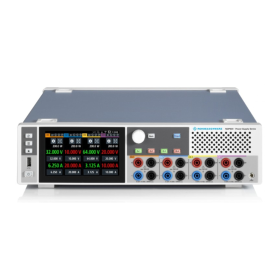
The following power supply models are available: Table 4-1: Power supply models Models Number of output channels NGP802, NGP822 NGP804, NGP814, NGP824 Figure 4-1: Front panel of R&S NGP800 power supply Getting Started 5601.5603.02 ─ 05... - Page 21 Output terminals (4) Two-channel instruments: NGP802 and NGP822 are equipped with 8 terminals for outputs and remote sense connections. Four-channel instruments: NGP804, NGP814 and NGP824 are equipped with 16 terminals for outputs and remote sense connections.
-
Page 22: Rear Panel
® Instrument Tour R&S NGP800 Overview of Controls For 64 V models, each output is capable to source 200 W of power at 0 V to 64 V and maximum current of 10A. Chassis ground terminal (5) A 4 mm socket is provided for the user to connect to earth ground through the instrument ground/chassis. - Page 23 11 = Ground terminal 12 = Kensington lock 13 = Channel 3 and 4 rear panel connector (for NGP804, NGP814 and NGP824 models only) 14 = Channel 1 and 2 rear panel connector 15 = Analog input and digital I/O connector...
- Page 24 ® Instrument Tour R&S NGP800 Overview of Controls Option IEEE-488 (GPIB) interface (10) Option R&S NG-B105 provides an IEEE-488 (GPIB) bus interface. Ground terminal (11) M4 screw provides connection to earth ground through the instrument ground/ chassis. Kensington security slot (12) A Kensington lock can be anchored to the R&S NGP800 power supply housing to secure it to a workstation mechanically.
-
Page 25: Switching On The Instrument
® Instrument Tour R&S NGP800 Switching On the Instrument USB connector (16) USB Type-B connector provides remote control operation via USB. Ethernet connector (17) 10/100 Ethernet port for remote control operation via the local area network. Switching On the Instrument Before switching on the instrument, check that all the instructions in the “Basic Safety Instruction”... -
Page 26: Trying Out The Instrument
® Trying Out the Instrument R&S NGP800 Setting the Output Voltage and Current Limit Trying Out the Instrument This chapter describes some basic functions that you can perform with the R&S NGP800 power supply series. Setting the Output Voltage and Current Limit 1. -
Page 27: Activating The Channels Output
® Trying Out the Instrument R&S NGP800 Activating the Channels Output 3. Enter the required value. 4. Confirm value with either a unit key or enter key The home window shows the updated voltage and current settings (See changes of voltage and current values in channel 1). 5. - Page 28 ® Trying Out the Instrument R&S NGP800 Activating the Channels Output To activate the channel output, press the [Output] key on the front panel followed by the desired channel key or vice versa. The R&S NGP800 power supply displays the actual voltage on the output chan- nel and the actual current drawn by the load connected to the output.
-
Page 29: Maintenance
® Maintenance R&S NGP800 Maintenance Regular maintenance improves the life span of the instrument, the following chap- ter provides information on instrument maintenance. Cleaning Before cleaning the instrument, ensure that it has been switched off and the power cable is disconnected. Clean the outer case of the instrument at regular intervals, using a soft, lint-free dust cloth. -
Page 30: Index
® Index R&S NGP800 Index Basic safety instructions ......5 Putting into operation ....... 9 Intended operation ......12 Safety ..........10 Unpacking and checking the instrument Calibration certificate ......... 6 ............13 Controls ........... 17 Rear panel Delivery package contents ...... 14 AC inlet with integrated 2-pole rocker Documentation overview ......
Need help?
Do you have a question about the NGP804 and is the answer not in the manual?
Questions and answers