Rohde & Schwarz NGP800 Series Getting Started
Hide thumbs
Also See for NGP800 Series:
- User manual (255 pages) ,
- Getting started (57 pages) ,
- Manual (7 pages)
Table of Contents
Advertisement
Quick Links
Advertisement
Table of Contents

Related Manuals for Rohde & Schwarz NGP800 Series


Summary of Contents for Rohde & Schwarz NGP800 Series
- Page 1 ® R&S NGP800 Power Supply Series Getting Started (Æ1Æ32) 5601560302 Version 11...
- Page 2 ® This manual describes the following R&S NGP800 models with firmware version 2.015 and higher: ● R&S ® NGP802 Two-channel 32V/20A Power Supply 400 W (5601.4007.05) ● R&S ® NGP822 Two-channel 64V/10A Power Supply 400 W (5601.4007.06) ● R&S ® NGP804 Four-channel 32V/20A Power Supply 800 W (5601.4007.02) ●...
-
Page 3: Table Of Contents
® Contents R&S NGP800 Contents 1 Safety information..............5 2 Korea certification class A............6 3 Documentation overview............7 3.1 Manuals....................7 3.2 Data sheet....................7 3.3 Calibration certificate................8 3.4 Release notes, open source acknowledgment........8 4 Welcome to R&S NGP800............. 9 5 Putting into operation............11 5.1 Safety.................... - Page 4 ® Contents R&S NGP800 8 Maintenance and support........... 30 8.1 Maintenance..................30 8.2 Contacting customer support............31 Index..................32 Getting Started 5601.5603.02 ─ 11...
-
Page 5: Safety Information
® Safety information R&S NGP800 Safety information The product documentation helps you use the R&S NGP800 safely and effi- ciently. Follow the instructions provided here and in the printed "Basic Safety Instructions". Keep the product documentation nearby and offer it to other users. Intended use The R&S NGP800 is intended for the development, production and verification of electronic components and devices in industrial, administrative, and laboratory... -
Page 6: Korea Certification Class A
® Korea certification class A R&S NGP800 Korea certification class A 이 기기는 업무용(A급) 전자파 적합기기로서 판매자 또는 사용자는 이 점을 주의하 시기 바라며, 가정외의 지역에서 사용하는 것을 목적으로 합니다. Getting Started 5601.5603.02 ─ 11... -
Page 7: Documentation Overview
® Documentation overview R&S NGP800 Data sheet Documentation overview This section provides an overview of the R&S NGP800 user documentation. Manuals You find the documents on the R&S NGP800 product page at: www.rohde-schwarz.com/product/ngp800 Getting started Introduces the R&S NGP800 power supply series and describes how to set up and start working with the instrument. -
Page 8: Calibration Certificate
® Documentation overview R&S NGP800 Release notes, open source acknowledgment www.rohde-schwarz.com/brochure-datasheet/ngp800 Calibration certificate The document is available on https://gloris.rohde-schwarz.com/calcert. You need the device ID of your instrument, which you can find on a label on the rear panel. Release notes, open source acknowledgment The release notes list new features, improvements and known issues of the cur- rent firmware version, and describe the firmware installation. -
Page 9: Welcome To R&S Ngp800
® Welcome to R&S NGP800 R&S NGP800 Welcome to R&S NGP800 The two or four-channel power supply series are based on a primary switched- mode regulator with power factor correction. This concept allows the instrument to achieve highest accuracy and lowest residual ripple. The R&S NGP800 power supply series feature galvanically isolated, overload and short-circuit proof outputs. - Page 10 ® Welcome to R&S NGP800 R&S NGP800 voltage signals (0 V to 5 V analog input corresponds to 0 to Vmax or Imax) and can be set independently for each channel. The analog inputs are galvanically isolated from the channel outputs, making the connection simpler. The digital I/O provides an 8-bit control port for various control functions.
-
Page 11: Putting Into Operation
® Putting into operation R&S NGP800 Putting into operation This chapter describes how to set up the R&S NGP800 power supply series for the first time. Risk of injury due to disregarding safety information Observe the information on appropriate operating conditions provided in the data sheet to prevent personal injury or damage to the instrument. - Page 12 ® Putting into operation R&S NGP800 Risk of radio interference This is a class A product. In a domestic environment, this product may cause radio interference in which case the user may be required to take adequate measures. Risk of instrument damage during operation An unsuitable operating site or test setup can cause damage to the instru- ment and the connected devices.
-
Page 13: Safety
® Putting into operation R&S NGP800 Safety Safety Recommendations on secure operation The R&S NGP800 is designed to operate at local workplaces or in secured networks (LAN). It should not be accessible from the internet, because of a potential security risk, e.g. attackers could misuse or damage your device. Please always install the latest firmware. -
Page 14: Intended Operation
® Putting into operation R&S NGP800 Intended operation Risk of electric shock It is prohibited to disconnect the earthed protective connection inside or out- side of the instrument! If it is assumed that a safe operation is no longer possible, the instrument must be shut down and secured against any unintended operation. - Page 15 ® Putting into operation R&S NGP800 Intended operation For safety reasons, the instrument may only be connected to properly installed wall outlets. Separating the ground is prohibited. The power cable must be inserted before signal circuits may be connected. Use only the power cable included in the delivery package. See "Delivery package"...
-
Page 16: Unpacking And Checking The Instrument
® Putting into operation R&S NGP800 Unpacking and checking the instrument Table 5-1: General data on instrument specification General data Mains nominal voltage 100 VAC to 250 VAC 50 Hz / 60 Hz Maximum input power 650 W for 2 channels 1125 W for 4 channels Mains fuses Internal 16 A 250 V IEC 60127-2/7 fast-acting... -
Page 17: Setting Up The Instrument
® Putting into operation R&S NGP800 Setting up the instrument Risk of damage during transportation and shipment Insufficient protection against mechanical and electrostatic effects during transportation and shipment can damage the instrument. ● Always ensure that sufficient mechanical and electrostatic protections are provided ●... -
Page 18: Bench Operation
® Putting into operation R&S NGP800 Setting up the instrument Risk of instrument damage due to high temperature Operate R&S NGP800 power supply in an area where the ambient temper- ature is within +5 °C to +40 °C. The R&S NGP800 power supply is fan-cooled and must be installed with sufficient space on the sides to allow proper air circulation. -
Page 19: Rack Mounting
® Putting into operation R&S NGP800 Setting up the instrument Risk of injury if feet are folded out The feet can fold in if they are not folded out completely or if the instrument is shifted. Collapsing feet can cause injury or damage the instrument. ●... -
Page 20: Instrument Tour
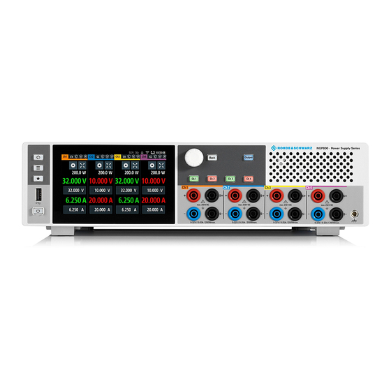
® Instrument tour R&S NGP800 Overview of controls Instrument tour This chapter provides an overview of all the controls available in the R&S NGP800 power supply series and steps to switch on the instrument for the first time. ● Overview of controls..................20 ●... - Page 21 ® Instrument tour R&S NGP800 Overview of controls 1 = Menu control keys 2 = Display with touch screen 3 = Rotary knob and back key 4 = Output and channel keys 5 = Chassis ground terminal (4mm socket) 6 = Output terminals (see Table 6-1) 7 = USB connector...
-
Page 22: Rear Panel
® Instrument tour R&S NGP800 Overview of controls Chassis ground terminal (5) A 4 mm socket is provided for the user to connect to earth ground through the instrument ground/chassis. Output terminals (6) Two-channel instrument models: R&S NGP802 and R&S NGP822 are equipped with 8 terminals for outputs and remote sense connections. - Page 23 ® Instrument tour R&S NGP800 Overview of controls Figure 6-2: Rear panel of R&S NGP800 power supply 9 = Ground terminal 10 = Optional IEEE-488 (GPIB) interface 11 = AC inlet with integrated 2-pole rocker switch 12 = Ethernet (LAN) connector 13 = USB-B connector (device) 14 = Analog input and digital I/O connector 15 = Channel 1 and 2 rear panel connector...
- Page 24 ® Instrument tour R&S NGP800 Overview of controls The power cable must be plugged in before signal circuits can be connected. Never use the product if the power cable is damaged. The built-in 2-pole rocker switch is the main power switch of the instrument which connects/disconnects it from the AC supply.
-
Page 25: Switching On The Instrument
® Instrument tour R&S NGP800 Switching on the instrument Channel connectors (15, 16) Output terminals Either the channel output terminals at the front panel or rear panel can be used. Using both terminals at the same time can cause instrument malfunc- tion. - Page 26 ® Instrument tour R&S NGP800 Switching on the instrument power is lit at the [Power] key on the front panel. If the standby power is lit, press the [Power] key to initiate the start-up sequence. To switch off instrument: 1. Press the [Power] key. The R&S NGP800 power supply initializes the power down sequence and enters into standby mode.
-
Page 27: Trying Out The Instrument
® Trying out the instrument R&S NGP800 Setting the output voltage and current limit Trying out the instrument This chapter describes some basic functions that you can perform with the R&S NGP800 power supply series. Setting the output voltage and current limit 1. -
Page 28: Activating The Channels Output
® Trying out the instrument R&S NGP800 Activating the channels output 3. Enter the required value. 4. Confirm value with either a unit key or enter key The home window shows the updated voltage and current settings (See changes of voltage and current values in channel 1). 5. - Page 29 ® Trying out the instrument R&S NGP800 Activating the channels output To activate the channel output, press the [Output] key on the front panel followed by the desired channel key or vice versa. The R&S NGP800 power supply displays the actual voltage on the output chan- nel and the actual current drawn by the load connected to the output.
-
Page 30: Maintenance And Support
® Maintenance and support R&S NGP800 Maintenance Maintenance and support Maintenance Regular maintenance improves the life span of the instrument, the following chap- ter provides information on instrument maintenance. Cleaning Before cleaning the instrument, ensure that it has been switched off and the power cable is disconnected. -
Page 31: Contacting Customer Support
® Maintenance and support R&S NGP800 Contacting customer support If the instrument cannot retain the date and time settings after turning off the AC input, the battery is discharged. Contact your local service partner for battery replacement. Contacting customer support Technical support –... -
Page 32: Index
® Index R&S NGP800 Index Calibration certificate ......... 8 Putting into operation .......11 Controls ........... 20 Intended operation ......14 Customer support ........31 Safety ..........13 Unpacking and checking the instrument ............16 Data sheet ..........7 Delivery package contents ...... 17 Documentation overview ......
Need help?
Do you have a question about the NGP800 Series and is the answer not in the manual?
Questions and answers