
Related Manuals for Rohde & Schwarz NGMO1


Summary of Contents for Rohde & Schwarz NGMO1
-
Page 1: Operating Manual
Operating Manual Power Supply NGMO1 Power Supply NGMO2 192.1500.21 and 192.1500.24 Version 4.00 / 07-2004... - Page 2 Operating Manual Power Supply NGMO1 and Power Supply NGMO2 Edition: July 2004 Version: 4.00 All rights reserved, including translation into foreign languages. No part of this manual may be re- produced or reworked using electronic systems, duplicated or distributed in any form (photo- copying, microfilm or any other process), not even for instructional purposes, without written permission from ROHDE &...
- Page 3 Safety Instructions This unit has been designed and tested in accordance with the EC Certificate of Conformity and has left the manufacturer’s plant in a condition fully complying with safety standards. To maintain this condition and to ensure safe operation, the user must observe all instructions and warnings given in this operating manual.
- Page 4 Safety Instructions Applicable local or national safety regulations 12. Equipment returned or sent in for repair must be and rules for the prevention of accidents must packed in the original packing or in packing with be observed in all work performed. electrostatic and mechanical protection.
-
Page 5: Table Of Contents
Contents Power Supply NGMO Contents Operator Information Preface NGMO-Versions 1.2.1 NGMO1 1.2.2 NGMO2 Purpose of the Handbook Explanation of Symbols Inspection Safety General Safety Instructions Unit Description Introduction Overview 3.2.1 Accessories Specifications Function Description 3.4.1 Communication Operation Operation Elements Start-Up 4.2.1... - Page 6 Power Supply NGMO Contents Measurements 4-23 4.5.1 Reading back Voltage (V), Current (I), DVM 4-23 4.5.2 Dynamic Measurements 4-23 Status Structure 4-28 4.6.1 Status Byte and SRQ 4-28 4.6.2 Queues 4-28 IEEE Commands IEEE-488.2 common commands and queries FORMAT command summary OUTPut command summary SENSE command summary SOURCE command summary...
- Page 7 Figures Power Supply NGMO Figures Fig. 3-1 NGMO2, Front view Fig. 3-2 NGMO2, Rear view Fig. 3-3 NGMO2, Pin codes Fig. 3-4 Circuit diagram: Mobile phone connected to the NGMO2 Fig. 4-1 NGMO2, Operation elements on the control panel Fig. 4-2 Four-wire sense connection 4-20 Fig.
-
Page 8: Version 4.00 /
Power Supply NGMO Tables Version 4.00 / 07-2004... -
Page 9: Operator Information
Power Supplies, such differences will be specially emphasized. The designation NGMO is used wherever the description applies for all versions. If you use this manual for a NGMO1: Just ignore all descriptions and specifications which belong to the channel B of the power supply. -
Page 10: Ngmo1
Power Supply NGMO Operator Information 1.2.1 NGMO1 The Power Supply NGMO1 consists of the following assemblies: Keyboard with LC Display • Processor board • Analog board for Channel A • Power supply unit • 1.2.2 NGMO2 The NGMO2 is equipped with two analog boards and therefore delivers two separate voltage sources and signal channels. -
Page 11: Explanation Of Symbols
Operator Information Power Supply NGMO Explanation of Symbols The Power Supply NGMO was produced according to the generally ac- cepted regulations governing the technology and current status of sci- ence and technology. However, it is impossible to design hazard-free electrical equipment. In order to guarantee a sufficient level of safety for personnel working with the Power Supply NGMO, safety regulations must be observed. -
Page 12: Inspection
Power Supply NGMO Operator Information Inspection The Power Supply NGMO2 was carefully inspected electrically and mechanically before shipment. After unpacking the unit from the ship- ping carton, check for any obvious signs of physical damage that may have occured in transit. Remove any protective film over the screen. Report any damage to the shipping agent immediately. -
Page 13: Safety
Safety Power Supply NGMO 2 Safety General NOTE Only personnel authorized by ROHDE & SCHWARZ may open the Power Supply NGMO. If the safety regulations for the Power Supply NGMO are disre- garded, ROHDE & SCHWARZ GmbH & Co KG will not assume liability for any resulting damage and all warranties will become null and void. - Page 14 Power Supply NGMO Safety 4.00 / 07-2004...
-
Page 15: Unit Description
The NGMO is more, than just a power supply for conventional test and measurement equipment, - it is an accurate, multipurpose electronic device with two separate supply and measurement channels (NGMO2 only, NGMO1 only Channel A) which can be used as the following: high speed voltage source, •... -
Page 16: Overview
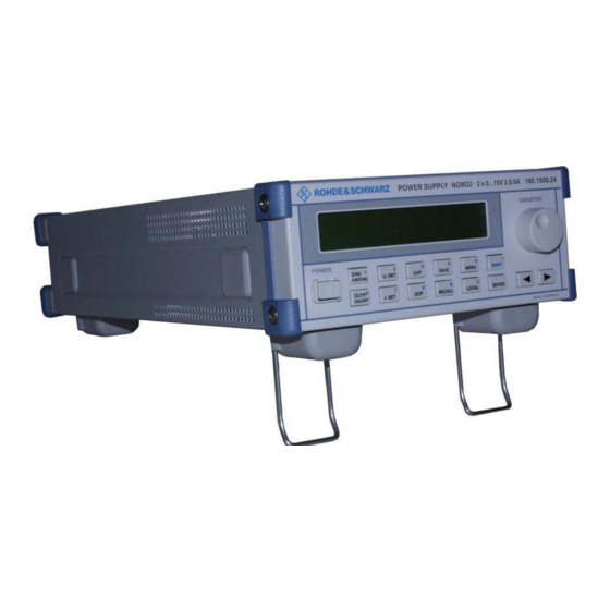
Power Supply NGMO Unit Description Overview Fig. 3-1 NGMO2, Front view pushbutton, POWER key 1, CHN, A/B/DVM key 6, OUTP., ON/OFF key 2, U-SET key 7, I-SET key 3, OVP key 8, OCP key 4, SAVE key 9, RECALL key 5, MENU key 0, LOCAL key, SHIFT key, ENTER... -
Page 17: Accessories
Unit Description Power Supply NGMO Fig. 3-2 NGMO2, Rear view Channel A Connector Channel B Connector Mains, 120/230 VAC Voltage Selector IEEE488.2 Connector RS485/232 Connector Control I/O Connector 3.2.1 Accessories 1 power cable, • 2 output connectors, • 1 operating manual •... -
Page 18: Specifications
Power Supply NGMO Unit Description Specifications Channel 1 Channel 2 Constant-voltage source - Voltage setting 0 to 15 V 0 to 15 V - Resolution 1 mV 1 mV - Deviation 0.05 % +5 mV 0.05 % +5 mV 0.5 mV 0.5 mV •... - Page 19 Unit Description Power Supply NGMO • deviation from full scale 10 mA 10 mA 1 mA 1 mA with ±10 % AC supply variation from 10 to 90 % load change 2.5 mA 2.5 mA • current sink capability 2.8 A (0 to 5 V) derating up 2.8 A (0 to 5 V) derating up to 1 A at 15 V to 1 A at 15 V...
- Page 20 Power Supply NGMO Unit Description - Analysis of values PEAK, MIN, PEAK, MIN, HIGH, LOW, HIGH, LOW, RMS, RMS, AVERage AVERage Protection Functions - OVP 1.5 to 22 V, settable 1.5 to 22 V, settable - OCP 0 to 5 A, settable 0 to 5 A, settable - Open-sense lead detection ±(0 to 4 V) about set...
-
Page 21: Function Description
Unit Description Power Supply NGMO Function Description 3.4.1 Communication Fig. 3-3 NGMO2, Pin codes Channel Relay Connector, rear panel, SUB 15, male Function Pin Function Signal DVM- RELOUT 1 output, relay driver, open collector 28 VDC/200 mA DVM+ RELOUT 2 output, relay driver, open collector 28 VDC/200 mA FORCE-... -
Page 22: Fig. 3-4 Circuit Diagram: Mobile Phone Connected To The Ngmo2
Power Supply NGMO Unit Description Fig. 3-4 Circuit diagram: Mobile phone connected to the NGMO2 The NGMO2 provides: 2 channels15 V/2.5 (5) A with 7 A • fast output transient response • sample buffer for fast current and voltage measurements •... -
Page 23: Operation
Fig. 4-1 shows the Operation Elements for the Power Supply NGMO2. NOTE: Operation elements and Start-up functions of the Power Supply NGMO1 are identical with the NGMO2. Operation elements for channel B must in this case be ignored. Readings in the LC Display correspond with the respective Power Supply. - Page 24 Power Supply NGMO Operation Function Type Function element pushbotton POWER This is the mains switch to turn the NGMO on and off. rotary knob VARIATION This knob has various functions: to increase or decrease numerical values in a menu function, •...
- Page 25 Operation Power Supply NGMO Function Type Function element 5; MENU Pressing the MENU key, allows you to select any of the 36 NGMO available optional functions with the variation knob. A menu need not necessarily have submenus. 6; OUTPUT; ON/OFF The ON/OFF key is used to turn the output of the current from the selected Power Supply (A, B or both) on or off.
- Page 26 Power Supply NGMO Operation General Note: All function keys in the middle of the control panel (CHN 1 • A/B/DVM to 0 LOCAL and SHIFT) are assigned two functions, e.g. apart from the main setting functions, the numerals 0 to 9 and the decimal point printed on the keys can be entered to alter values when the shift key has been pressed.
-
Page 27: Start-Up
Operation Power Supply NGMO Start Up 4.2.1 NGMO Line Power Connection and Power-up The NGMO operates from a line voltage in the range 120/230 VAC at a frequency between 47 and 63 Hz. Proceed as follows to connect the NGMO to the AC line and turn on: Before plugging in the power cable, make sure that the power switch is off (the “POWER“... - Page 28 Operation Power Supply NGMO Example 1 line 1: "AS" means that currently the settings for channel A are displayed. • If you turn the output on by pressing the "OUTP. on/off" key the display changes to "AM" indicating that this is now a measured value taken from the output terminals of the selected power supply.
- Page 29 Power Supply NGMO Operation manual setting keys are disabled except the local key and those to change the display mode. This makes it easier for software deve- lopers to verify that their software is running correctly. When a lock command has been received from the IEEE interface the NGMO2 enters the lock state.
-
Page 30: Menu
Operation Power Supply NGMO 4.2.3 Menu There are two ways of entering numerical settings. The first way is to use the variation knob (16, Fig. 3-1) and the arrow keys (14, 15, Fig. 3-1). The second is to use the keys with the extra blue labels. 4.2.3.1 How to Enter a Numerical Value Using the Variation Knob? - Page 31 Power Supply NGMO Operation NOTE: If you are in the Menu mode and you have selected a function that accepts numerical entries, the direct numerical input mode can be activated by pressing the SHIFT key without first pres- sing the ENTER key. However, it is also possible to first select the variation knob entry mode by pressing the ENTER key and then entering the direct numerical entry mode by pressing the SHIFT key.
- Page 32 Operation Power Supply NGMO 4.2.3.4 Menu Items The menu includes a selection of items from A01 or B01 to A38 or B38: (The indicated channel A or B depends on which channel is selected.) A/B01: Current range [AUTO] 5A .5A 5mA This function selects the range for static current measure- ment (see main screen) and also selects the current range for signal analysis.
- Page 33 Power Supply NGMO Operation A/B06: Sample Channel [Current DVM] This menu items lets you select the source for the NGMO2 analysis functions. When “current” is selected the analysis functions use the internal current measure circuits for analysis (ranges 5A or .5A). In “DVM” mode the external DVM inputs are used for analysis.
- Page 34 Operation Power Supply NGMO A/B11: Trigger Source [int] ext The trigger source function lets you select either an internal trigger source (see A/B07 to A/B09) or use an external trigger signal to start an analysis measurement. The external trigger signal can be applied on the rear panel.
- Page 35 Power Supply NGMO Operation A/B16: Sample Interval (0.01-1000 ms) The sample interval is the time interval between two consecutive samples used for measurement or signal analysis. Both the “Sample length” and the “Sample Interval” makes the total measuring time for one sample cycle.
- Page 36 Operation Power Supply NGMO A/B20: READ xxx Value (Result) The “READ xxx Value” menu item (xxx = AVER PEAK MIN HIGH LOW RMS) (see also A/B19) displays the result for the selected analysis function. If there is no result available (because there is no data that can be analyzed) only a line is displayed.
- Page 37 Power Supply NGMO Operation A/B25: Relay 1 [on] off Turns the output driver for relay 1 on or off. The driver signal is applied to the “Control I/O” connector, Pin 1 on the rear panel (ground on pin 8 and 9). A/B26: Relay 2 [on] off...
- Page 38 Operation Power Supply NGMO A/B31: Serial interface [on] off When set to ON, a RS232 connection to the NGMO2 can be used as a remote interface. This setting is independent of the setting made with menu item 29 (Recall setting when power on).
- Page 39 Power Supply NGMO Operation A/B35: Serial count of stopbits [1] 2 This menu item is used to select “Serial count of stopbits” for data transmission. When set to 1, only one stopbit is transmitted before the start of the next data byte. When set to 2, two stopbits are transmitted before the next data byte - this means synchronisation is better but there are fewer transfers per second.
- Page 40 Operation Power Supply NGMO A/B38: Calibration mode Press ENT to select After pressing the enter key the user enters the calibration mode for the NGMO. See Service Manual – Chapter 7 (192.1500.82) NOTE: The calibration of the Power Supply NGMO has to be made by Rohde &...
-
Page 41: Test Connections
Power Supply NGMO Operation Test Connections ELECTROCUTION HAZARDS! Observe the relevant safety regulations when operating electri- cal devices. Do not float the power supply output more than 25 V from chassis. Otherwise, in addition to the output voltage above 50 VDC can increase at the terminals and present electric shock hazard to the operator. -
Page 42: Local Sense
Operation Power Supply NGMO 4.3.2 Local sense Fig. 4-3 Local sense connections The NGMO2 can be connected to operate with local sense leads (2- wire connection) as shown in Fig. 4-3. When this connection sche- me is used the sense inputs and supply outputs are jumpered at the rear of the NGMO2. -
Page 43: Factory Defaults
Power Supply NGMO Operation Factory Defaults The NGMO can be set to power up using the factory default conditions or the user-saved setup conditions. The factory defaults are listed in chapter 5 IEEE Commands. 4-22 4.00 / 07-2004... - Page 44 Power Supply NGMO Operation Meaning: x.yy is the version number of the currently installed firmware • = major version number, yy = minor version number. nn = currently selected IEEE address for the device • Az = type of power supply board mounted at location A in the •...
-
Page 45: Measurements
Operation Power Supply NGMO Measurements The NGMO2 provides three multiplexed measure channels on each supply channel (A/B) for the measurement of output VOLTAGE and CURRENT as well as for the additional DVM input. The VOLTAGE channel is used only for static measure functions (readback), CURRENT and DVM channels are used for static and dynamic measu- re functions. -
Page 46: Fig. 4-4 Sample Values
Power Supply NGMO Operation sample value. That is important to protect against losing information when observing signals over a long time period. The sample interval can be set between 10 µs and 1 s in 10 µs steps. At sample intervals greater than 10 µs the NGMO2 measure system samples internally in 10 µs intervals and averages the taken samples to build values in the selected time intervals. -
Page 47: Fig. 4-5 Pre-Trigger And Post-Trigger Acquisition
Operation Power Supply NGMO 4.5.2.1 Trigger System A dynamic measurement sequence is specified by the selected sample interval (0.01 ... 1000.00 ms) and the required number of sample points (Sample Length: 1... 5000). It is initialized by starting the sample mode (Sample Start >... -
Page 48: Fig. 4-6 Measurement Repetition
Power Supply NGMO Operation Fig. 4-6 Measurement repetition NOTE: The post- or pre-trigger is only available for a single sample sequence (triggercount = 1). With a selected triggercount > 1 data acquisition starts at the trigger signal for any sequence. For each measurement range the trigger level is settable in the speci- fied value borders with the given resolution of that range. - Page 49 Operation Power Supply NGMO PEAK: The absolute highest sample that occurs during the measu- rement sequence is stored as the PEAK value. MIN: Analogous to PEAK the absolute lowest sample value is u- sed to form the MIN value. For the computation of the HIGH, LOW, AVERage and RMS values a imaginary „change level“...
-
Page 50: Status Structure
Power Supply NGMO Operation Status Structure The NGMO2 provides a series of status registers and queues allowing the operator to monitor and manipulate the various instrument events. The status structure is shown in Fig. 4-4. The heart of the status struc- ture is the status byte register. -
Page 51: Fig. 4-7 Status Model Structure
Operation Power Supply NGMO Fig. 4-7 Status model structure 4.00 / 07-2004 4-29... - Page 52 Power Supply NGMO Operation 4-30 4.00 / 07-2004...
-
Page 53: Ieee Commands
IEEE Commands Power Supply NGMO 5 IEEE Commands * = Factory defaults <NUM_VAL> = integer or real <CHAR_VAL> = string IEEE-488-2 common commands and queries Com- Parameter Par. value Description Def. SCPI mand *CLS See status Clears all event model registers and error structure for queues... - Page 54 Power Supply NGMO IEEE Commands Com- Parameter Par. value Description Def. SCPI mand *RST Returns the power supply to the *RST default conditions *SAV <CHAR_VAL> or Saves the present <NUM_VAL> setup as the user- saved setup (1..9) First user setting Ninth user setting First user setting Ninth user setting...
- Page 55 IEEE Commands Power Supply NGMO Com- Parameter Par. value Description Def. SCPI mand *BTRg Sends a “SENSE:PULSE:S TART ON" and a soft trigger command to channel B *TST? Performs a checksum test on ROM and returns 0 for test OK and 1 for test failed *WAI Waits until all...
- Page 56 Power Supply NGMO IEEE Commands Com- Parameter Par. value Description Def. SCPI mand DVMB 4.00 / 07-2004...
-
Page 57: Format Command Summary
IEEE Commands Power Supply NGMO FORMAT command summary Com- Parameter Par. value Description Def. SCPI mand :FORMat [:DATA] <CHAR_VAL> Specifies the ASCII output data format for Fetch, Read and Message command. ASCii ASCII LONG Long integer SREal Short real DREal Double real ASCII DEFault... -
Page 58: Output Command Summary
Power Supply NGMO IEEE Commands OUTPut command summary Com- Parameter Par. value Description Def. SCPI mand :OUT [:A] <CHAR_VAL> Turns output A off <CHAR_VAL> Turns output A on :OUT <CHAR_VAL> Turns output B off <CHAR_VAL> Turns output B on :OUTPut [:A] Channel A / Channel 1... - Page 59 IEEE Commands Power Supply NGMO Com- Parameter Par. value Description Def. SCPI mand :BAND- <CHAR_VAL> Selects slow or fast HIGH width regulation speed HIGH Bandwidth high Bandwidth low Bandwidth high DEFault Bandwidth high Bandwidth low DISPlay Sets LCD to OUTPUT BANDWIDTH :BAND- <CHAR_VAL>...
- Page 60 Power Supply NGMO IEEE Commands Com- Parameter Par. value Description Def. SCPI mand Closes Opens DEFault Opens Closes DISPlay Sets LCD to RELAIS <n> :RELay1? Relay 1 :RELay2? Relay 2 :RELay3? Relay 3 :RELay4? Relay 4 <CHAR_VAL> Queries the ON / OFF state of the corresponding relay port pin /...
-
Page 61: Sense Command Summary
IEEE Commands Power Supply NGMO SENSE command summary Com- Parameter Par. value Description Def. SCPI mand :SENSe [:A] Channel A / Channel 1 :SENSe[1] Channel A / Channel 1 :SENSe Channel B / Channel 2 :SENSe2 Channel B / Channel 2 :FUNCtion <CHAR_VAL>... - Page 62 Power Supply NGMO IEEE Commands Com- Parameter Par. value Description Def. SCPI mand LOW or 0.005[A] AUTO Auto ranging Auto ranging DEFault DISPlay Sets LCD to: CURRENT RANGE :CURRent [:DC] :RANGe [:UPPer]? <CHAR_VAL> Queries current range HIGH MEDIUM AUTO AUTO DEFault HIGH :MEASure :INTerval...
- Page 63 IEEE Commands Power Supply NGMO Com- Parameter Par. value Description Def. SCPI mand DISPlay Sets LCD to STATIC AVERAGE COUNT :AVERage [:COUNt]? <CHAR_VAL> Queries measure- ment interval Results: 1 <= NUM_VAL <= 10 DEFault :PULSe :TRIGger :STATe? Queries current trigger status Results: NONE TRIGGERED...
- Page 64 Power Supply NGMO IEEE Commands Com- Parameter Par. value Description Def. SCPI mand DISPlay Sets LCD to SAMPLE START :PULSe [:MEAS- :STARt? <CHAR_VAL> Queries pulse ure] measurement status Results: DEFault :PULSe [:MEAS- :TYPE <CHAR_VAL> Selects pulse AVER ure] measurement and read type AVERage Average...
- Page 65 IEEE Commands Power Supply NGMO Com- Parameter Par. value Description Def. SCPI mand 1E-4 <= NUM_VAL <= 7 DEFault :PULSe :TRIGger :LEVel :LOW <CHAR_VAL> or Sets trigger level 2.5 mA <NUM_VAL> for 0.5A (LOW) range 1.00E-05 0.01 mA 500 mA AUTO or 0 Auto trigger 0A ->...
- Page 66 Power Supply NGMO IEEE Commands Com- Parameter Par. value Description Def. SCPI mand Intern DEFault Intern Extern DISPlay Sets LCD to TRIGGER SOURCE :PULSe :TRIGger :SOURce? <CHAR_VAL> Queries trigger source Results: DEFault :PULSe :TRIGger SLOPe <CHAR_VAL> Selects trigger slope Positive Negative Positive DEFault...
- Page 67 IEEE Commands Power Supply NGMO Com- Parameter Par. value Description Def. SCPI mand DEFault 1.00 5000.00 :PULSe :TRIGger :OFFSet <CHAR_VAL> or Sets trigger offset 0 <NUM_VAL> -5000 Trigger offset -5000 50000 Trigger offset 50000 Trigger offset -5000 DEFault Trigger offset 0 Trigger offset 50000 DISPlay...
- Page 68 Power Supply NGMO IEEE Commands Com- Parameter Par. value Description Def. SCPI mand Triggers timeout infinite DEFault Trigger timeout infinite Trigger timeout 60 DISPlay Sets LCD to TRIGGER TIMEOUT :PULSe :TRIGger :TIMeout? <CHAR_VAL> Queries trigger timeout Results: 0 <= NUM_VAL <= 60 INFINITE DEFault...
-
Page 69: Source Command Summary
IEEE Commands Power Supply NGMO SOURCE command summary Com- Parameter Par. value Description Def. SCPI mand :SOURce [:A] Channel A / Channel 1 :SOURce Channel A / Channel 1 :SOURce Channel B / Channel 2 :SOURce2 Channel B / Channel 2 :VOLTage :PROTec- <CHAR_VAL>... - Page 70 Power Supply NGMO IEEE Commands Com- Parameter Par. value Description Def. SCPI mand DEFault :VOLTage [:LEVel] [:IMMedi- [:AMPLi- <CHAR_VAL> or Sets voltage amp- ate] tude] <NUM_VAL> litude in 1 mV steps 0.000 0 Volt 15.000 15 Volt 0 Volt DEFault 0 Volt 15 Volt DISPlay...
- Page 71 IEEE Commands Power Supply NGMO Com- Parameter Par. value Description Def. SCPI mand DISPlay Sets LCD to: Maximum output current :CURRent [:LIMit] :MAXSet- <CHAR_VAL> Queries max. ing? settable current limit Results: 0.000 <= NUM_VAL <= 5.000 DEFault :CURRent [:LIMit] :TYPE <CHAR_VAL>...
-
Page 72: Status Command Summary
Power Supply NGMO IEEE Commands STATUS command summary Com- Parameter Par. value Description Def. SCPI mand :STATus General Status commands :MEAS- [:EVENt]? Read the urement measurement event register. See status model structure for further information. Results: 0 to 32767 :MEAS- :ENABle <NUM_VAL>... - Page 73 IEEE Commands Power Supply NGMO Com- Parameter Par. value Description Def. SCPI mand :OPER- :COND- Read the ation ition? operation condition register.See status model structure for further information Results: 0 to 32767 :QUES- [:EVENt]? Read the tionable questionable event register. See status model structure for further information...
-
Page 74: Config Command Summary
Power Supply NGMO IEEE Commands CONFIG command summary Com- Parameter Par. value Description Def. SCPI mand :CONFig [:A] Channel A / Channel 1 :CONFig Channel A / Channel 1 :CONFig Channel B / Channel 2 :CONFig2 Channel B / Channel 2 :CURRent :LIMit :BEEP <CHAR_VAL>... -
Page 75: System Command Summary
IEEE Commands Power Supply NGMO SYSTEM command summary Com- Parameter Par. value Description Def. SCPI mand :SYSTem :POSetup <CHAR_VAL> or Selects default LAST- <NUM_VAL> setting for power Factory settings First user-saved setting Ninth user-saved setting Last front panel setup Factory settings SAV1 First user-saved setting... - Page 76 Power Supply NGMO IEEE Commands Com- Parameter Par. value Description Def. SCPI mand :SYSTem :CLEar Clears the error queue :SYSTem :COMM- :SERial :ENABle <CHAR_VAL> Enables or unicate disables the serial interface Disable Enable Disable DEFault Disable Enable DISPlay Sets LCD to: Serial Interface ON/OFF :SYSTem :COMM-...
- Page 77 IEEE Commands Power Supply NGMO Com- Parameter Par. value Description Def. SCPI mand 38400 DEFault 9600 38400 :SYSTem :COMM- :SERial :DATabits <CHAR_VAL> or Sets serial data unicate <NUM_VAL> length 7 bits 8 bits 7 bits DEFault 8 bits 8 bits DISPlay Sets LCD to: Serial count of...
- Page 78 Power Supply NGMO IEEE Commands Com- Parameter Par. value Description Def. SCPI mand 2 stopbits DISPlay Sets LCD to: Serial count of stopbits :SYSTem :COMM- :SERial :STOPbits <CHAR_VAL> Queries number unicate of stopbits Results: DEFault :SYSTem :COMM- :SERial :HAND- <CHAR_VAL> Sets serial NONE unicate...
- Page 79 IEEE Commands Power Supply NGMO Com- Parameter Par. value Description Def. SCPI mand :SYSTem :COMM- :IEEe :ADDRess <CHAR_VAL> or Sets the IEEE unicate <NUM_VAL> address Address nr. 01 Address nr. 30 Address nr. 01 DEFault Address nr. 05 Address nr. 30 DISPlay Sets LCD to: IEEE Address...
-
Page 80: Signal-Oriented Measurement-Command Summary
Power Supply NGMO IEEE Commands Signal-oriented measurement-command sum- mary Com- Parameter Par. value Description Def. SCPI mand :FETCh [:A]? Channel A / Channel 1 :FETCh[1] Channel A / Channel 1 :FETCh Channel B / Channel 2 :FETCh2? Channel B / Channel 2 Returns the last triggered reading. - Page 81 IEEE Commands Power Supply NGMO Com- Parameter Par. value Description Def. SCPI mand :MEASure [:A]? Channel A / Channel 1 :MEASure Channel A / [1]? Channel 1 :MEASure :B? Channel B / Channel 2 :MEASure Channel B / Channel 2 Performs a READ.
-
Page 82: Remote Calibration Command Summary
Power Supply NGMO IEEE Commands 5.10 Remote calibration command summary Com- Parameter Par. value Description Def. SCPI mand :CAL :ENTer :PROT :CODe <NUM_VAL> 1...99999999 Unlocks 2222 calibration code :CAL :CHANge :PROT :CODe <NUM_VAL> 1...99999999 Sets new calibration code :CAL [:A] Channel A / Channel 1 :CAL[1]... -
Page 83: Ordering Information
6 Ordering Information Pos. Name Part Supplier Part number Service Manual for Rohde & Schwarz, 192.1500.82 NGMO1 and NGMO2 Cologne Department: The Service Manual provides the 5 CE information necessary for calibration, Phone: fault finding and fault rectification on 49 (0)2203-51357 the NGMO. - Page 84 Power Supply NGMO Ordering Information 4.00 / 07-2004...
Need help?
Do you have a question about the NGMO1 and is the answer not in the manual?
Questions and answers