Rohde & Schwarz NGP800 Series Getting Started
Hide thumbs
Also See for NGP800 Series:
- User manual (255 pages) ,
- Getting started (32 pages) ,
- Manual (7 pages)
Table of Contents
Advertisement
Quick Links
Advertisement
Table of Contents

Subscribe to Our Youtube Channel
Related Manuals for Rohde & Schwarz NGP800 Series


Summary of Contents for Rohde & Schwarz NGP800 Series
- Page 1 ® R&S NGP800 Power Supply Series Getting Started (Æ1Æ32) 5601560302 Version 12...
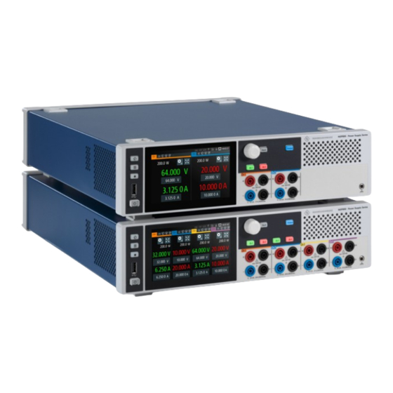
- Page 2 ® This manual describes the following R&S NGP800 models with firmware version 2.025 and higher: ● R&S ® NGP802 Two-channel 32V/20A Power Supply 400 W (5601.4007.05) ● R&S ® NGP822 Two-channel 64V/10A Power Supply 400 W (5601.4007.06) ● R&S ® NGP804 Four-channel 32V/20A Power Supply 800 W (5601.4007.02) ●...
-
Page 3: Table Of Contents
® Contents R&S NGP800 Contents 1 Safety and regulatory information........5 1.1 Safety instructions................6 1.2 Labels on R&S NGP800................9 1.3 Warning messages in the documentation........10 1.4 Korea certification class A..............11 2 Documentation overview............ 12 2.1 Manuals....................12 2.2 Data sheet....................13 2.3 Calibration certificate................. - Page 4 ® Contents R&S NGP800 5 Instrument tour..............27 5.1 Front panel..................27 5.2 Rear panel....................30 6 Trying out the instrument........... 34 6.1 Selecting the channels............... 34 6.2 Setting the output voltage and current limit........34 6.3 Activating the channels output............36 6.4 Saving/Recalling of instrument settings..........
-
Page 5: Safety And Regulatory Information
® Safety and regulatory information R&S NGP800 Safety and regulatory information The product documentation helps you use the product safely and efficiently. Fol- low the instructions provided here and in the following chapters. Intended use The product is intended for the development, production and verification of elec- tronic components and devices in industrial, administrative, and laboratory envi- ronments by personnel familiar with the potential risks of measuring electrical quantities. -
Page 6: Safety Instructions
® Safety and regulatory information R&S NGP800 Safety instructions Safety instructions Products from the Rohde & Schwarz group of companies are manufactured according to the highest technical standards. To use the products safely, follow the instructions provided here and in the product documentation. Keep the prod- uct documentation nearby and offer it to other users. - Page 7 ® Safety and regulatory information R&S NGP800 Safety instructions ments where nonconductive contamination can occur. For more information on environmental conditions such as ambient temperature and humidity, see the data sheet. Setting up the product Always place the product on a stable, flat and level surface with the bottom of the product facing down.
- Page 8 ® Safety and regulatory information R&S NGP800 Safety instructions ● Only connect the product to a power source with the safety fuse specified in the data sheet. ● Ensure that you can disconnect the product from the power source at any time.
-
Page 9: Labels On R&S Ngp800
® Safety and regulatory information R&S NGP800 Labels on R&S NGP800 Measurement categories IEC 61010-2-030 defines measurement categories that rate products on their ability to resist short transient overvoltages that occur in addition to the working voltage. This product is designed for measuring within measurement category 0 only. Measurements in this category are performed on circuits not directly connected to mains, such as electronics, battery powered circuits, and specially protected sec- ondary circuits. -
Page 10: Warning Messages In The Documentation
® Safety and regulatory information R&S NGP800 Warning messages in the documentation Table 1-1: Labels regarding R&S NGP800 and environment safety Labeling in line with EN 50419 for disposal of electrical and electronic equipment after the product has come to the end of its service life. For more information, see the prod- uct user manual, chapter "Disposal". -
Page 11: Korea Certification Class A
® Safety and regulatory information R&S NGP800 Korea certification class A Korea certification class A 이 기기는 업무용(A급) 전자파 적합기기로서 판매자 또는 사용자는 이 점을 주의하 시기 바라며, 가정외의 지역에서 사용하는 것을 목적으로 합니다. Getting Started 5601.5603.02 ─ 12... -
Page 12: Documentation Overview
® Documentation overview R&S NGP800 Manuals Documentation overview This section provides an overview of the R&S NGP800 user documentation. Manuals You find the documents on the R&S NGP800 product page at: www.rohde-schwarz.com/product/ngp800 Getting started Introduces the R&S NGP800 power supply series and describes how to set up and start working with the instrument. -
Page 13: Data Sheet
® Documentation overview R&S NGP800 Release notes, open source acknowledgment (OSA) Data sheet The datasheet contains the technical specifications of the R&S NGP800 power supply series. It also lists all options with their order numbers and accessories. www.rohde-schwarz.com/brochure-datasheet/ngp800 Calibration certificate The document is available on https://gloris.rohde-schwarz.com/calcert. -
Page 14: Welcome To R&S Ngp800
® Welcome to R&S NGP800 R&S NGP800 Welcome to R&S NGP800 The two or four-channel power supply series are based on a primary switched- mode regulator with power factor correction. This concept allows the instrument to achieve highest accuracy and lowest residual ripple. The R&S NGP800 power supply series feature galvanically isolated, overload and short-circuit proof outputs. - Page 15 ® Welcome to R&S NGP800 R&S NGP800 voltage signals (0 V to 5 V analog input corresponds to 0 to Vmax or Imax) and can be set independently for each channel. The analog inputs are galvanically isolated from the channel outputs, making the connection simpler. The digital I/O provides an 8-bit control port for various control functions.
-
Page 16: Preparing For Use
® Preparing for use R&S NGP800 Unpacking and checking Preparing for use Here, you can find basic information about setting up the product for the first time. Lifting and carrying "Lifting and carrying the product" on page 6. Unpacking and checking 1. -
Page 17: Choosing The Operating Site
® Preparing for use R&S NGP800 Setting up the R&S NGP800 ● One document folder with multilingual safety instruction and CE certificate Choosing the operating site Specific operating conditions ensure proper operation and avoid damage to the product and connected devices. For information on environmental conditions such as ambient temperature and humidity, see the data sheet. -
Page 18: Placing The R&S Ngp800 On A Bench Top
® Preparing for use R&S NGP800 Setting up the R&S NGP800 4.4.1 Placing the R&S NGP800 on a bench top To place the product on a bench top 1. Place the product on a stable, flat and level surface. Ensure that the surface can support the weight of the product. -
Page 19: Mounting The R&S Ngp800 In A Rack
® Preparing for use R&S NGP800 Setting up the R&S NGP800 4.4.2 Mounting the R&S NGP800 in a rack To prepare the rack 1. Observe the requirements and instructions in "Setting up the product" on page 7. 2. NOTICE! Insufficient airflow can cause overheating and damage the product. The heat produced inside the instrument is guided to the exterior via tempera- ture-controlled fan. -
Page 20: Considerations For Test Setup
® Preparing for use R&S NGP800 Considerations for test setup 3. If placing the R&S NGP800 on a bench top again, unmount the adapter kit from the R&S NGP800. Follow the instructions provided with the adapter kit. Considerations for test setup The product is built in compliance with DIN EN 61010-1 (VDC 0411 part 1), EN 61010-1 and IEC 61010-1. - Page 21 ® Preparing for use R&S NGP800 Considerations for test setup Operating limits The R&S NGP800 is equipped with a protective overload feature. The protective overload feature prevents damage to the instrument and is intended to protect against a possible electrical shock. The maximum values for the instrument must not be exceeded.
-
Page 22: Connecting To Power
® Preparing for use R&S NGP800 Connecting to power ● Check regularly that all cables, including power cables are in perfect condi- tions. Signal input and output levels Information on voltage levels is provided in the data sheet. Keep the voltage lev- els within the specified ranges to avoid damage to the product and connected devices. -
Page 23: Switching On Or Off
® Preparing for use R&S NGP800 Switching on or off Ground terminal If necessary, ground the instrument using the grounding connection located at rear panel: 1. Unscrew the screw of the ground terminal using a cross-recess screw driver. 2. Attach a ground cable with a ring terminal and pass the screw through it. 3. -
Page 24: Connecting To Lan
® Preparing for use R&S NGP800 Connecting to LAN All current settings are saved and the operating system shuts down. The LED of the power key changes to red. To disconnect from power The product is in the standby state. 1. -
Page 25: Connecting Usb Devices
® Preparing for use R&S NGP800 Connecting USB devices Possible reasons are that the LAN does not support DCHP or requires a spe- cific TCP/IP configuration, or that the connection is missing. To troubleshoot the problem, proceed as follows: a) Check if you have connected both, the R&S NGP800 and the controller PC to the LAN. - Page 26 ® Preparing for use R&S NGP800 Connecting USB devices If you use the front panel connectors, connect the USB storage device directly, without connecting cable. Connecting cables can cause electromagnetic radi- ation and impair the measurement result. Getting Started 5601.5603.02 ─ 12...
-
Page 27: Instrument Tour
® Instrument tour R&S NGP800 Front panel Instrument tour The following sections help you to get familiar with the instrument and perform the first steps: ● Chapter 5.1, "Front panel", on page 27 ● Chapter 5.2, "Rear panel", on page 30 These sections explain the controls and connections on the front and rear panel of the R&S NGP800. - Page 28 ® Instrument tour R&S NGP800 Front panel Figure 5-1: Front panel of R&S NGP800 power supply 1 = Menu control keys 2 = Display with touch screen 3 = Rotary knob and back key 4 = Output and channel keys 5 = Chassis ground terminal (4mm socket) 6 = Output terminals (see Table...
- Page 29 ® Instrument tour R&S NGP800 Front panel Rotary knob and back key (3) The rotary knob and back key are used for menu navigation and value adjustment in the instrument. For a detailed description on navigation, see "To enter values by using the front panel controls"...
-
Page 30: Rear Panel
® Instrument tour R&S NGP800 Rear panel powered up and the instrument will startup to operate normally. The LED illumina- tion is turned off in this state. See also Chapter 4.7, "Switching on or off", on page 23. Rear panel Figure 5-2 shows the rear panel of the R&S NGP800 power supply with its con- nectors. - Page 31 ® Instrument tour R&S NGP800 Rear panel AC inlet with integrated 2-pole rocker switch (11) Main supply cord Use a detachable mains supply cord according to IEC60320-1 standard. Never use the product if the power cable is damaged. The built-in 2-pole rocker switch is the main power switch of the instrument which connects/disconnects the R&S NGP800 from the AC supply, see Chapter 4.6, "Connecting to...
- Page 32 ® Instrument tour R&S NGP800 Rear panel Table 5-2: Pin configurations DIO & analog Signal Logical name Value range Pin number input connector Analog input 1 to ANA1 0 Vdc to 5 Vdc ANA2 ANA3 ANA4 Analog ground 0 Vdc 6, 14 Digital ground 0 Vdc...
- Page 33 ® Instrument tour R&S NGP800 Rear panel 1. DANGER! Shock Hazard. Risk of electric shock if AC power is turned on when connecting wires to the rear panel connector. Turn off AC power when connecting wires to the rear panel connector. 2.
-
Page 34: Trying Out The Instrument
® Trying out the instrument R&S NGP800 Setting the output voltage and current limit Trying out the instrument This chapter describes some basic functions that you can perform with the R&S NGP800 power supply series. Selecting the channels To select a channel, press the corresponding channel key. The selected channel key illuminates. - Page 35 ® Trying out the instrument R&S NGP800 Setting the output voltage and current limit The R&S NGP800 power supply displays an on-screen keypad to set the value. 3. Enter the required value. 4. Confirm value with either a unit key or enter key, The home window shows the updated voltage and current settings (see changes of voltage and current values in "Ch1").
-
Page 36: Activating The Channels Output
® Trying out the instrument R&S NGP800 Activating the channels output Activating the channels output The output voltages can be switched on or off regardless of the instrument's oper- ating mode. To activate the channel output, press the [Output] key on the front panel followed by the desired channel key or vice versa. -
Page 37: Saving/Recalling Of Instrument Settings
® Trying out the instrument R&S NGP800 Saving/Recalling of instrument settings Saving/Recalling of instrument settings The R&S NGP800 can save instrument settings and screenshots. Both instru- ment settings and screenshots can be saved on a USB stick or internally in the instrument to non-volatile storage media. -
Page 38: Instrument Control
® Instrument control R&S NGP800 Means of manual interaction Instrument control This chapter provides an overview on how to work with the R&S NGP800. It intro- duces the possibilities for operating the instrument and describes the basic func- tionality of the control elements. If a measurement configuration requires specific operating steps, the corresponding settings description in the user manual points it out separately. - Page 39 ® Instrument control R&S NGP800 Means of manual interaction parameters in dialogs, enter data using online keypads and swipe to scroll within a dialog. – Tapping Tap on the screen to select or toggle the value. – Swipe up and down Swipe up to scroll down and swipe down to scroll up the content in the menu or dialog box.
-
Page 40: Understanding The Display Information
® Instrument control R&S NGP800 Means of manual interaction 7.2.1 Understanding the display information Depending on the instrument models, up to two or four home windows are shown on the screen layout. The respective channel settings and device status are dis- played for each channel. - Page 41 ® Instrument control R&S NGP800 Means of manual interaction ● Device status ● Channel status Device status The device status displays the state of the functions activated in the device. Figure 7-1: Device status bar Table 7-2: Device status bar information Function Description If touch input is disabled, the icon is displayed...
- Page 42 ® Instrument control R&S NGP800 Means of manual interaction Function Description Only visible if software option Wireless LAN is WLAN active and instrument with serial number below 110000. If connection is present, the icon is highlighted in white. If both WLAN and LAN connection are present, the icon is highlighted with a line cross over.
- Page 43 ® Instrument control R&S NGP800 Means of manual interaction Function Description If enabled, the icon is highlighted in white. If triggered, the icon blinks. See chapter "Overvoltage protection (OVP)" in the user manual. If enabled, the icon is highlighted in white. If triggered, the icon blinks.
-
Page 44: Settings Softkey
® Instrument control R&S NGP800 Means of manual interaction 7.2.1.2 Settings softkey The "Settings" softkey, navigates to the instrument (device/channel) menu win- dow. Alternate access to instrument menu is via the [Settings] key on the front panel. See also chapter "Settings key" in user manual. Long press on the "Settings"... -
Page 45: Historical Channel Information
® Instrument control R&S NGP800 Means of manual interaction Figure 7-3: Channel display area for 4-channel model 1 = "Settings" softkey opens instrument menu window. 2 = "Expand/Collapse" softkey toggles between home window and the detailed channel display area window, see Figure 7-4 3 = Output power displays in watt 4 = Output voltage displays in volt with display resolution of three decimal points... -
Page 46: Operating Mode
® Instrument control R&S NGP800 Means of manual interaction Figure 7-4: Detailed channel display area of a 4-channel instrument model Settings softkey Expand/Collapse softkey Historical channel information Channel display area of respective channel 5 = Digital I/O trigger configuration To change the voltage or current value, see Chapter 7.2.3.1, "Entering numeric parameters", on page 52. -
Page 47: Additional Display Characteristics
® Instrument control R&S NGP800 Means of manual interaction Figure 7-5: Color coding of difference operating conditions Color Operating mode Description OFF mode Output is OFF. Editing mode A solid blue cursor is shown when an item is selected. CV mode Active outputs are operated in a constant voltage mode. - Page 48 ® Instrument control R&S NGP800 Means of manual interaction – Selected element is framed or highlighted orange. – Inactive elements are gray. Figure 7-6: Appearance of active elements ● Menus and dialogs Both, menus and dialogs appear similar, and contain selection lists. Through- out this manual, a list of functions which lead you to the settings of this func- tion is referred to as menu.
- Page 49 ® Instrument control R&S NGP800 Means of manual interaction The term dialog refers to the views that cover the parameters of a certain function. Figure 7-8: Example of a dialog ● Wizards The measurement wizard is provided to perform a sequence of standardized and recurring measurements with guided instructions during the measure- ment.
-
Page 50: Accessing The Functionality
® Instrument control R&S NGP800 Means of manual interaction Figure 7-10: On-screen keyboard for alphanumeric and numeric entry field ● Info dialogs An "Info dialog" appears when an event generates a message. The generi- cally assigned header shows the affected topic. The message describes the event, and short instructions lead you through the next steps. -
Page 51: Entering Data
® Instrument control R&S NGP800 Means of manual interaction To open the dialog ► Select the corresponding menu item from the displayed menu, i.e. "Interfaces" > "USB Class" The corresponding dialog is displayed. To close or exit a dialog or menu To close or exit a dialog or menu, you have several options. -
Page 52: Entering Numeric Parameters
® Instrument control R&S NGP800 Means of manual interaction To correct an entry 1. To delete an entry, set the cursor to the right of the entry you want to delete. To select the position: a) Select it in the entry field directly. b) Use the cursor softkeys of the on-screen keypad. -
Page 53: Entering Alphanumeric Parameters
® Instrument control R&S NGP800 Remote control To enter values by using the front panel controls You can also change the parameters with the navigation controls on the front panel, e.g if you have locked the touchscreen. However, these front panel con- trols work only In the home window and detailed channel display area window. - Page 54 ® Instrument control R&S NGP800 Remote control ● USB standard interface ● IEEE-488 bus interface (GPIB) (option: R&S NG-B105) For detailed information on how to configure the remote control interfaces, see chapter "Interfaces and Protocols" in the user manual. Chapter 4.8, "Connecting to LAN", on page 24 for an example of how to set up LAN connection for remote control.
-
Page 55: Contacting Customer Support
® Contacting customer support R&S NGP800 Contacting customer support Technical support – where and when you need it For quick, expert help with any Rohde & Schwarz product, contact our customer support center. A team of highly qualified engineers provides support and works with you to find a solution to your query on any aspect of the operation, program- ming or applications of Rohde &... -
Page 56: Index
® Index R&S NGP800 Index Rotary knob ........29 USB connector ........29 Access Front panel keys Instrument ........... 50 Usage ..........39 Active elements ........47 Fuses Alphanumeric parameters ....... 53 How to replace the power fuse ... 22 Bench top, placing the R&S NGP800 ..18 Getting started ......... - Page 57 ® Index R&S NGP800 Keypad Remote control ........38, 53 On-screen ........... 51 Interfaces ..........53 Replace the power fuse How to: ..........22 Lifting the instrument ....... 16 Safety instructions ....... 6, 12 SCPI programmers manual ..... 12 Manual interaction ........38 Security procedures ........
Need help?
Do you have a question about the NGP800 Series and is the answer not in the manual?
Questions and answers