Table of Contents
Advertisement
Quick Links
Advertisement
Table of Contents

Related Manuals for Rohde & Schwarz R&S NGC100 Series


Summary of Contents for Rohde & Schwarz R&S NGC100 Series
- Page 1 ® R&S NGC100 Power Supply Series Getting Started (;Ý@Y2) 1179164102 Version 01...
- Page 2 ® This manual describes the instruments of the R&S NGC power supply series: ● R&S ® 101 Single-channel power supply 100W (3657.2288.02) ● R&S ® 101-G Single-channel power supply 100W GPIB (3657.2288.03) ● R&S ® 102 Two-channel power supply 100W (3657.2359.02) ●...
-
Page 3: Table Of Contents
® Contents R&S NGC100 Contents 1 Safety and regulatory information........5 1.1 Safety instructions................6 1.2 Labels on R&S NGC100................9 1.3 Warning messages in the documentation........10 1.4 Korea certification class A..............11 2 Documentation overview............ 12 2.1 Manuals....................12 2.2 Data sheet....................13 2.3 Calibration certificate................. - Page 4 ® Contents R&S NGC100 4.9 Connecting USB devices..............25 5 Instrument tour..............27 5.1 Front panels..................27 5.2 Rear panel....................31 6 Trying out the instrument........... 35 6.1 Selecting the channels............... 35 6.2 Setting the output voltage and current limits........35 6.3 Activating the channel output............
-
Page 5: Safety And Regulatory Information
® Safety and regulatory information R&S NGC100 Safety and regulatory information The product documentation helps you use the product safely and efficiently. Fol- low the instructions provided here and in the following chapters. Intended use The product is intended for the development, production and verification of elec- tronic components and devices in industrial, administrative, and laboratory envi- ronments by personnel familiar with the potential risks of measuring electrical quantities. -
Page 6: Safety Instructions
® Safety and regulatory information R&S NGC100 Safety instructions Safety instructions Products from the Rohde & Schwarz group of companies are manufactured according to the highest technical standards. To use the products safely, follow the instructions provided here and in the product documentation. Keep the prod- uct documentation nearby and offer it to other users. - Page 7 ® Safety and regulatory information R&S NGC100 Safety instructions ments where nonconductive contamination can occur. For more information on environmental conditions such as ambient temperature and humidity, see the data sheet. Setting up the product Always place the product on a stable, flat and level surface with the bottom of the product facing down.
- Page 8 ® Safety and regulatory information R&S NGC100 Safety instructions ● Only use intact cables and route them carefully so that they cannot be dam- aged. Check the power cables regularly to ensure that they are undamaged. Also ensure that nobody can trip over loose cables. ●...
-
Page 9: Labels On R&S Ngc100
® Safety and regulatory information R&S NGC100 Labels on R&S NGC100 ● Ensure that all products are grounded by connecting them to the AC power. ● Disconnect all power connections to the product, including outputs. Measurement categories IEC 61010-2-030 defines measurement categories that rate products on their ability to resist short transient overvoltages that occur in addition to the working voltage. -
Page 10: Warning Messages In The Documentation
® Safety and regulatory information R&S NGC100 Warning messages in the documentation ● Device information is provided on a sticker attached to the rear panel R&S NGC100. The sticker contains a barcode and the device ID. The device ID is a combination of the order number and the serial number. Table 1-1: Labels regarding R&S NGC100 and environment safety Labeling in line with EN 50419 for disposal of electrical and electronic equipment after the product has come to the end of its service life. -
Page 11: Korea Certification Class A
® Safety and regulatory information R&S NGC100 Korea certification class A NOTICE Potential risks of damage. Could result in damage to the supported product or to other property. Korea certification class A 이 기기는 업무용(A급) 전자파 적합기기로서 판매자 또는 사용자는 이 점을 주의하 시기... -
Page 12: Documentation Overview
® Documentation overview R&S NGC100 Manuals Documentation overview This section provides an overview of the R&S NGC100 user documentation. Manuals You find the documents on the R&S NGC100 product page at: www.rohde-schwarz.com/manual/ngc100 Getting started Introduces the R&S NGC100 power supply series and describes how to set up and start working with the instrument. -
Page 13: Data Sheet
® Documentation overview R&S NGC100 Application notes, application cards, white paper, etc. Instrument security procedures manual Deals with security issues when working with the R&S NGC100 in secure areas. It is available for download on the internet. Data sheet The datasheet contains the technical specifications of the R&S NGC100 power supply series. -
Page 14: Remote Control Driver
® Documentation overview R&S NGC100 Remote control driver www.rohde-schwarz.com/application/ngc100 Remote control driver The instrument drivers enable remote control via the corresponding interfaces. The drivers and installation instructions are available for download on the product page at: www.rohde-schwarz.com/driver/ngc100 Getting Started 1179.1641.02 ─ 01... -
Page 15: Welcome To R&S Ngc100
® Welcome to R&S NGC100 R&S NGC100 Welcome to R&S NGC100 The one, two or three-channel power supply series are based on a classical transformer concept with linear regulators. This concept allows the instrument to achieve highest accuracy and lowest residual ripple. Key features All output channels of R&S NGC100 are galvanically isolated, floating and protec- ted against overloading and short-circuit. -
Page 16: Preparing For Use
® Preparing for use R&S NGC100 Choosing the operating site Preparing for use Here, you can find basic information about setting up the product for the first time. Lifting and carrying "Lifting and carrying the product" on page 6. Unpacking and checking 1. -
Page 17: Setting Up The R&S Ngc100
® Preparing for use R&S NGC100 Setting up the R&S NGC100 – Residential environments – Environments that are directly connected to a low-voltage supply network that supplies residential buildings ● Class A equipment is intended for use in industrial environments. It can cause radio disturbances in residential environments due to possible conducted and radiated disturbances. -
Page 18: Mounting The R&S Ngc100 In A Rack
® Preparing for use R&S NGC100 Setting up the R&S NGC100 ● Do not exceed a total load of 50 kg placed on the product at the bottom of the stack. Left = Stacked correctly Middle left = Stacked incorrectly, too many products Middle right = Stacked incorrectly, different dimensions Right = Stacked incorrectly, folded-out feet... -
Page 19: Considerations For Test Setup
® Preparing for use R&S NGC100 Considerations for test setup To mount the R&S NGC100 in a rack 1. Use an adapter kit that fits the dimensions of the R&S NGC100 to prepare the R&S NGC100 for rack mounting. a) Order the rack adapter kit designed for the R&S NGC100. For the order number, see data sheet. - Page 20 ® Preparing for use R&S NGC100 Considerations for test setup Table 4-1: General data on instrument specification Mains nominal voltage 100 VAC to 240 VAC (±10 %), 50 Hz / 60 Hz Power consumption Maximum input power 200 W Mains fuses 100 V to 240 V IEC 60127-2/5: T3.15H250V...
-
Page 21: Connecting To Power
® Preparing for use R&S NGC100 Connecting to power Specification Limits Maximum reverse current Power supply 100 VAC to 240 VAC (±10 %) Frequency 50 Hz / 60 Hz Maximum power output 100 W Cable selection and electromagnetic interference (EMI) Electromagnetic interference (EMI) can affect the measurement results. - Page 22 ® Preparing for use R&S NGC100 Connecting to power The power supply module covers a wide power supply range and normally does not require adjustment. See Table 4-1 for the supported mains voltage and the corresponding fuse types and ratings. If the power supply exceeds the permissi- ble range, contact Rohde &...
-
Page 23: Switching On Or Off
® Preparing for use R&S NGC100 Switching on or off Ground terminal If necessary, ground the instrument using the grounding connection located at rear panel: 1. Unscrew the screw of the ground terminal using a cross-recess screw driver. 2. Attach a ground cable with a ring terminal and pass the screw through it. 3. -
Page 24: Connecting To Lan
® Preparing for use R&S NGC100 Connecting to LAN All current settings are saved and the operating system shuts down. The LED of the power key changes to red. To disconnect from power The product is in the standby state. 1. -
Page 25: Connecting Usb Devices
® Preparing for use R&S NGC100 Connecting USB devices Possible reasons are that the LAN does not support DCHP or requires a spe- cific TCP/IP configuration, or that the connection is missing. To troubleshoot the problem, proceed as follows: a) Check if you have connected both, the R&S NGC100 and the controller PC to the LAN. - Page 26 ® Preparing for use R&S NGC100 Connecting USB devices If you use the front panel connectors, connect the USB storage device directly, without connecting cable. Connecting cables can cause electromagnetic radi- ation and impair the measurement result. Getting Started 1179.1641.02 ─ 01...
-
Page 27: Instrument Tour
® Instrument tour R&S NGC100 Front panels Instrument tour The following sections help you to get familiar with the instrument and perform the first steps: ● Chapter 5.1, "Front panels", on page 27 ● Chapter 5.2, "Rear panel", on page 31 The sections explain the controls and connections on the front and rear of the R&S NGC100. - Page 28 ® Instrument tour R&S NGC100 Front panels Figure 5-1: R&S NGC103(-G) front panel Figure 5-2: R&S NGC102(-G) front panel Getting Started 1179.1641.02 ─ 01...
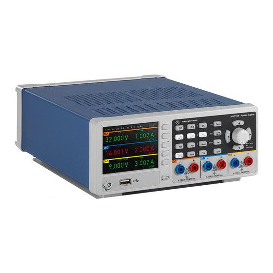
- Page 29 ® Instrument tour R&S NGC100 Front panels Figure 5-3: R&S NGC101(-G) front panel Display Interactive softkeys Function keys Navigation controls Output terminals Back key USB connector Power key Derating graph Display (1) The display is a color LCD screen. Depending on the instrument models, up to three channels are shown on the screen layout with different result fields are dis- played.
- Page 30 ® Instrument tour R&S NGC100 Front panels Interactive softkeys (2) The interactive softkeys on the right of the display set the view of the measuring mode and provide access to submenus and functions. The interactive softkeys are not illuminated. If your instrument model does not support a specific operating mode, function or parameter, the access area to the interactive softkey menu is dimmed.
-
Page 31: Rear Panel
® Instrument tour R&S NGC100 Rear panel Table 5-2: Power key state Power key state Descriptions Power on, ready state. The LED turns off. The instrument is ready for operation. Power on, standby mode. The LED turns red. The instrument is connec- ted to power. - Page 32 ® Instrument tour R&S NGC100 Rear panel 10 = IEEE-488 (GPIB) interface 11 = AC power supply 12 = Kensington lock 13 = Ground terminal 14 = USB interface 15 = Ethernet (LAN) interface 16 = Rear panel connector IEEE-488 (GPIB) interface (10) Available with variant 03 model (i.e.
- Page 33 ® Instrument tour R&S NGC100 Rear panel Ground terminal (13) Protective ground terminal to secure the R&S NGC100, e.g. with a ground exter- nal conductor, see Chapter 1.2, "Labels on R&S NGC100", on page 9. USB connector (14) The USB connector is a Type-B connector for remote control operation via USB TMC or USB VCP.
- Page 34 ® Instrument tour R&S NGC100 Rear panel Figure 5-5: Terminal block with connector assignment = Corresponds to + socket on the front panel = Corresponds to - socket on the front panel S+, S- = SENSE connectors U+, U- = Voltage interface or external trigger input I+, I- = Current interface 1.
-
Page 35: Trying Out The Instrument
® Trying out the instrument R&S NGC100 Setting the output voltage and current limits Trying out the instrument This chapter describes some basic functions that you can perform with the R&S NGC100. Selecting the channels For R&S NGC102(-G) and R&S NGC103(-G) models, select a channel by press- ing the corresponding channel key. -
Page 36: Activating The Channel Output
® Trying out the instrument R&S NGC100 Activating the channel output 4. Press the [Up] / [Down] arrow key to change the value. Alternatively, turn the rotary knob to change the value. The new value registers immediately. 5. To directly set the numerical values, press the [Shift] key on the front panel. The [Shift] key switches the function keys to a numeric keypad to change the value. -
Page 37: Storing/Recalling Of Instrument Settings
® Trying out the instrument R&S NGC100 Storing/Recalling of instrument settings Depending on the instrument operating mode, the display font color changes to green in CV (constant voltage) mode and red in CC (constant current) mode. By default, the output is turned off when the instrument is switched on. See also Chapter 7.2.1.3, "Operating modes",... -
Page 38: Instrument Control
® Instrument control R&S NGC100 Means of manual interaction Instrument control This chapter provides an overview on how to work with the R&S NGC100. It intro- duces the possibilities for operating the instrument and describes the basic func- tionality of the control elements. If a measurement configuration requires specific operating steps, the corresponding settings description in the user manual points it out separately. -
Page 39: Understanding The Display Information
® Instrument control R&S NGC100 Means of manual interaction The front panel function keys followed by the corresponding interactive keys provide nearly all the functions and controls needed to operate the instrument. When selected, i.e. a function is active, the corresponding function key lights up in white. - Page 40 ® Instrument control R&S NGC100 Means of manual interaction For more information of statistic function, see "Statistic function" on page 43. Table 7-1: Screen layout of R&S NGC100 models R&S NGC101(-G) R&S NGC102(-G) R&S NGC103(-G) ● Device status bar ● Interactive softkey menus (e.g.
- Page 41 ® Instrument control R&S NGC100 Means of manual interaction Function Description "Log" Measurement function: Data logging. Provides capturing and storage of measurement values. "Stat" Statistic reading of minimum, maximum, mean and count values for voltage and current. <W> Displays total power consumption. "In TrigRise"...
- Page 42 ® Instrument control R&S NGC100 Means of manual interaction Table 7-3: Channel status bar information Indicator Description <Channel> Channel number indication. "Set" and "Meas" Depending on instrument models supported, up to three channels ("Ch1", "Ch2", "Ch3") are displayed. For R&S NGC101(-G) model, the top channel display area displays the configured or "Set"...
- Page 43 ® Instrument control R&S NGC100 Means of manual interaction on. See Chapter 7.2.1.3, "Operating modes", on page 43 for the different operat- ing modes that the R&S NGC100 supported. Statistic function At the bottom of the screen layout is the display of statistic values (minimum, maximum, mean and count) for voltage and current for each channel.
- Page 44 ® Instrument control R&S NGC100 Means of manual interaction Figure 7-3: Color coding of difference operating conditions Color Operating mode Description OFF mode or edit- Output is OFF. ing mode In editing mode, a solid white cursor is shown when an item is selected.
- Page 45 ® Instrument control R&S NGC100 Means of manual interaction – Information indicated in red denotes that the setting is inactive or errone- ous. – "---" dashes on the display indicate that the R&S NGC100 could not deter- mine a value. ●...
-
Page 46: Accessing The Functionality
® Instrument control R&S NGC100 Means of manual interaction Figure 7-7: On-screen keyboard ● "Fallback" time, an adjustable time period: When this time period has elapsed, the instrument either closes a setting dia- log, returns to a previous dialog or assigns a certain setting automatically with- out having confirmed manually. -
Page 47: Entering Data
® Instrument control R&S NGC100 Means of manual interaction The instrument returns to previous menu level or exit the menu mode if it is already at the main menu level. To select a parameter in a dialog All except the arbitrary editor dialog have its parameters fixed at the softkey menu for selection. - Page 48 ® Instrument control R&S NGC100 Means of manual interaction – Activates the edit mode of a parameter when pressed. – Acts like the [ENTER] key when it is pressed. – Increments (by turning clockwise) or decrements (counterclockwise) a numeric parameter. –...
-
Page 49: Remote Control
® Instrument control R&S NGC100 Remote control To complete the entry ► Press the rotary knob. For directly setting of numeric values, you can complete the entry with a selection of unit softkeys or using default unit by pressing the rotary knob. 7.2.3.2 Entering alphanumeric parameters If a field requires alphanumeric input, you can use the on-screen keyboard to... - Page 50 ® Instrument control R&S NGC100 Remote control Remote control interfaces The R&S NGC100 provides several interfaces for remote control: ● Ethernet (LAN) interface ● USB standard interface For detailed information on how to configure the remote control interfaces, see chapter "Interfaces and protocols" in the user manual. Chapter 4.8, "Connecting to LAN", on page 24 for an example of how to set...
-
Page 51: Contacting Customer Support
® Contacting customer support R&S NGC100 Contacting customer support Technical support – where and when you need it For quick, expert help with any Rohde & Schwarz product, contact our customer support center. A team of highly qualified engineers provides support and works with you to find a solution to your query on any aspect of the operation, program- ming or applications of Rohde &... -
Page 52: Index
® Index R&S NGC100 Index Display Active elements ........44 Access Front panel ..........29 Instrument menus ....... 46 Key fallback time .........44 Active elements ........44 On-screen keypad ......44 Alphanumeric parameters ....... 49 Display information ........39 Application cards ........13 Documentation overview ...... - Page 53 ® Index R&S NGC100 Ground terminal ........23 Mount the instrument in a rack ... 19 Navigation controls Replace the power fuse ...... 22 Front panel ..........30 Select the channels ......35 Numeric data entry ........47 Set output voltage and current limits .. 35 Numeric parameters ........
- Page 54 ® Index R&S NGC100 Release notes ......... 13 Remote control ........49 Ways of operation ........38 Driver ..........14 White papers ........... 13 Interfaces ..........50 Replace the power fuse How to: ..........22 Safety information ........5 Safety instructions ....... 6, 12 SCPI programmers manual .....
Need help?
Do you have a question about the R&S NGC100 Series and is the answer not in the manual?
Questions and answers