Table of Contents
Advertisement
Quick Links
Advertisement
Table of Contents

Subscribe to Our Youtube Channel
Related Manuals for Rohde & Schwarz R&S NGA100 Series


Summary of Contents for Rohde & Schwarz R&S NGA100 Series
- Page 1 ® R&S NGA100 Power Supply Series Getting Started (Æ1ç22) 5601890202 Version 08...
- Page 2 ® This manual describes the following R&S NGA100 models with firmware version 1.00 and higher: ● R&S ® NGA101 One-Channel 35V/6A Power Supply 40 W (5601.8002.02) ● R&S ® NGA102 Two-Channel 35V/6A Power Supply 80 W (5601.8002.04) ● R&S ® NGA141 One-Channel 100V/2A Power Supply 40 W (5601.8002.03) ●...
-
Page 3: Table Of Contents
® Contents R&S NGA100 Contents 1 Safety and regulatory information........5 1.1 Safety instructions................6 1.2 Labels on R&S NGA100................9 1.3 Warning messages in the documentation........10 1.4 Korea certification class A..............11 2 Documentation overview............ 12 2.1 Manuals....................12 2.2 Data sheet....................13 2.3 Calibration certificate................. - Page 4 ® Contents R&S NGA100 5.3 Bottom panel..................31 6 Trying out the instrument........... 33 6.1 Selecting the channels............... 33 6.2 Setting the output voltage and current limit........33 6.3 Activating the channel output............34 6.4 Storing/Recalling of instrument settings..........34 7 Instrument control............... 35 7.1 Ways to operate the instrument............
-
Page 5: Safety And Regulatory Information
® Safety and regulatory information R&S NGA100 Safety and regulatory information The product documentation helps you use the product safely and efficiently. Fol- low the instructions provided here and in the following chapters. Intended use The product is intended for the development, production and verification of elec- tronic components and devices in industrial, administrative, and laboratory envi- ronments by personnel familiar with the potential risks of measuring electrical quantities. -
Page 6: Safety Instructions
® Safety and regulatory information R&S NGA100 Safety instructions Safety instructions Products from the Rohde & Schwarz group of companies are manufactured according to the highest technical standards. To use the products safely, follow the instructions provided here and in the product documentation. Keep the prod- uct documentation nearby and offer it to other users. - Page 7 ® Safety and regulatory information R&S NGA100 Safety instructions ments where nonconductive contamination can occur. For more information on environmental conditions such as ambient temperature and humidity, see the data sheet. Setting up the product Always place the product on a stable, flat and level surface with the bottom of the product facing down.
- Page 8 ® Safety and regulatory information R&S NGA100 Safety instructions ● Only use intact cables and route them carefully so that they cannot be dam- aged. Check the power cables regularly to ensure that they are undamaged. Also ensure that nobody can trip over loose cables. ●...
-
Page 9: Labels On R&S Nga100
® Safety and regulatory information R&S NGA100 Labels on R&S NGA100 ● Ensure that all products are grounded by connecting them to the AC power. ● Disconnect all power connections to the product, including outputs. Measurement categories IEC 61010-2-030 defines measurement categories that rate products on their ability to resist short transient overvoltages that occur in addition to the working voltage. -
Page 10: Warning Messages In The Documentation
® Safety and regulatory information R&S NGA100 Warning messages in the documentation ● Device information is provided on a sticker attached to the rear panel of R&S NGA100. The sticker contains a barcode and the device ID. The device ID is a combination of the order number and the serial number. -
Page 11: Korea Certification Class A
® Safety and regulatory information R&S NGA100 Korea certification class A NOTICE Potential risks of damage. Could result in damage to the supported product or to other property. Korea certification class A 이 기기는 업무용(A급) 전자파 적합기기로서 판매자 또는 사용자는 이 점을 주의하 시기... -
Page 12: Documentation Overview
® Documentation overview R&S NGA100 Manuals Documentation overview This section provides an overview of the R&S NGA100 user documentation. Manuals You find the documents on the R&S NGA100 product page at: www.rohde-schwarz.com/manual/nga100 Getting started Introduces the R&S NGA100 power supply series and describes how to set up and start working with the instrument. -
Page 13: Data Sheet
® Documentation overview R&S NGA100 Release notes, open source acknowledgment (OSA) Data sheet The datasheet contains the technical specifications of the R&S NGA100 power supply series. It also lists all options with their order numbers and accessories. www.rohde-schwarz.com/brochure-datasheet/nga100 Calibration certificate The document is available on https://gloris.rohde-schwarz.com/calcert. -
Page 14: Welcome To R&S Nga100
® Welcome to R&S NGA100 R&S NGA100 Welcome to R&S NGA100 The one-channel or two-channel power supply series are based on a classical transformer concept with high efficiency electronic pre-regulators and secondary linear regulators. This concept allows the instrument to achieve the high output power within a minimum space, high efficiency and lowest residual ripple. -
Page 15: Preparing For Use
® Preparing for use R&S NGA100 Unpacking and checking Preparing for use Here, you can find basic information about setting up the product for the first time. Lifting and carrying "Lifting and carrying the product" on page 6. Unpacking and checking 1. -
Page 16: Choosing The Operating Site
® Preparing for use R&S NGA100 Setting up the R&S NGA100 ● One document folder with multilingual safety instruction and CE certificate Choosing the operating site Specific operating conditions ensure proper operation and avoid damage to the product and connected devices. For information on environmental conditions such as ambient temperature and humidity, see the data sheet. - Page 17 ® Preparing for use R&S NGA100 Setting up the R&S NGA100 4.4.1 Placing the R&S NGA100 on a bench top To place the product on a bench top 1. Place the product on a stable, flat and level surface. Ensure that the surface can support the weight of the product.
- Page 18 ® Preparing for use R&S NGA100 Setting up the R&S NGA100 4.4.2 Mounting the R&S NGA100 in a rack To prepare the rack 1. Observe the requirements and instructions in "Setting up the product" on page 7. 2. NOTICE! Insufficient airflow can cause overheating and damage the product. The heat produced inside the instrument is guided to the exterior via tempera- ture-controlled fan.
-
Page 19: Considerations For Test Setup
® Preparing for use R&S NGA100 Considerations for test setup 3. If placing the R&S NGA100 on a bench top again, unmount the adapter kit from the R&S NGA100. Follow the instructions provided with the adapter kit. Considerations for test setup The product is built in compliance with DIN EN 61010-1 (VDC 0411 part 1), EN 61010-1 and IEC 61010-1. - Page 20 ® Preparing for use R&S NGA100 Considerations for test setup Weight R&S NGA101, R&S NGA141 6.6 kg (14.55 lb), 6.9 kg (15.21 R&S NGA102, R&S NGA142 7.0 kg (15.43 lb), 7.3 kg (16.09 Operating limits The R&S NGA100 is equipped with a protective overload feature. The protective overload feature prevents damage to the instrument and is intended to protect against a possible electrical shock.
-
Page 21: Connecting To Power
® Preparing for use R&S NGA100 Connecting to power ● Use at least a CAT6+ LAN cables with a length ≤ 3 m and passive USB cable with a length ≤ 1m. ● Use insulated wires for output supply/terminal connections ●... - Page 22 ® Preparing for use R&S NGA100 Connecting to power Replacing the power fuse By default, the R&S NGA100 is preloaded with two time lag fuses (IEC 60127 T2.5H250V). The fuse holder is located below the AC power connector. 1. Disconnect the product from the power source by removing the power cable from the power plug on the rear panel of the R&S NGA100.
-
Page 23: Switching On Or Off
® Preparing for use R&S NGA100 Switching on or off Switching on or off Specifications with tolerance data apply after a warm-up period of at least 30 minutes at a temperature of 23 °C (tolerance -3 °C / +7 °C). Before switching on the instrument, check that the voltage selector corresponds... -
Page 24: Connecting To Lan
® Preparing for use R&S NGA100 Connecting to LAN Connecting to LAN Establishing the LAN connection The R&S NGA100 provides Ethernet (LAN) connectivity. Provided the corre- sponding rights are assigned, you can use these interfaces for remote control and data transfer from a controller PC. The controller PC must also be connected in the network. -
Page 25: Connecting Usb Devices
® Preparing for use R&S NGA100 Connecting USB devices Figure 4-2: Ethernet settings dialog Connecting USB devices The USB Type-A connector is at the front panel. You can connect or disconnect all USB devices from the R&S NGA100 during operation. But do not remove an external USB memory stick while the instrument is performing firmware update, data logging and storing of screen captures, since it leads to unsuccessful updates and loss of data. -
Page 26: Instrument Tour
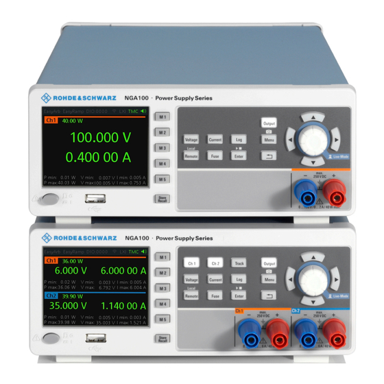
® Instrument tour R&S NGA100 Front panel Instrument tour The following sections help you to get familiar with the instrument and perform the first steps: ● Chapter 5.1, "Front panel", on page 26 ● Chapter 5.2, "Rear panel", on page 29 ●... - Page 27 ® Instrument tour R&S NGA100 Front panel Figure 5-1: Front panel of R&S NGA100 with two channels 1 = Display 2 = Function keys 3 = Rotary knob and arrow keys 4 = Output channels (see Table 5-1) 5 = USB connector 6 = Power key Display (1) The display is a color LCD screen.
- Page 28 ® Instrument tour R&S NGA100 Front panel Rotary knob and arrow keys (3) Rotary knob and arrow keys are means of navigation and adjustment. When pressed or rotated, they perform tasks like navigation around the screen, adjust- ment of parameter values or confirmation of entries. For detailed description on rotary knob and arrow keys, see Chapter 7.2, "Means of manual...
-
Page 29: Rear Panel
® Instrument tour R&S NGA100 Rear panel Rear panel Figure 5-2: Rear panel of R&S NGA100 7 = Ground terminal 8 = AC inlet with fuse holder 9 = Ethernet (LAN) connector 10 = USB connector 11 = Digital I/O connector 12 = Rear panel connector 13 = Kensington lock Ground terminal (7) - Page 30 ® Instrument tour R&S NGA100 Rear panel Socket for the fuse securing the line voltage. The fuse is factory fitted. See "Replacing the power fuse" on page 22. ● IEC socket Power supply connector for connecting the R&S NGA100 to the mains, see Chapter 4.6, "Connecting to power", on page 21.
-
Page 31: Bottom Panel
® Instrument tour R&S NGA100 Bottom panel Rear panel connector (12) Output terminals Either the output terminals at the front panel or the rear panel connector at the back panel can be used. Both terminals cannot be used at the same time as it can cause the instru- ment to malfunction. - Page 32 ® Instrument tour R&S NGA100 Bottom panel Figure 5-3: Bottom panel of R&S NGA100 14 = Voltage selector 15 = Voltage selector label Voltage selector (14), Voltage selector label (15) The voltage selector selects the mains voltage between 100 V, 115 V and 230 V. Table 4-1 for the fuse rating.
-
Page 33: Trying Out The Instrument
® Trying out the instrument R&S NGA100 Setting the output voltage and current limit Trying out the instrument This chapter describes some basic functions that you can perform with the R&S NGA100. Selecting the channels To select a channel, press the corresponding channel key. The selected channel key illuminates. -
Page 34: Activating The Channel Output
® Trying out the instrument R&S NGA100 Storing/Recalling of instrument settings Activating the channel output The output voltages can be switched on or off regardless of the operating mode of the instrument. To activate the channel output, press the [Output] key on the front panel followed by the desired channel key or vice versa. -
Page 35: Instrument Control
® Instrument control R&S NGA100 Means of manual interaction Instrument control This chapter provides an overview on how to work with the R&S NGA100. It intro- duces the possibilities for operating the instrument and describes the basic func- tionality of the control elements. If a measurement configuration requires specific operating steps, the corresponding settings description in the user manual points it out separately. - Page 36 ® Instrument control R&S NGA100 Means of manual interaction The navigation controls include a rotary knob and arrow keys ([Up], [Down], [Left], [Right]). The arrow keys allow you to navigate on the channel display screen or dialogs to set parameters. For basic instructions on how to control the R&S NGA100, see Chapter 7.2.2, "Accessing the...
- Page 37 ® Instrument control R&S NGA100 Means of manual interaction ● Device status ● Channel status Device status The device status displays the state of the functions activated in the device. Figure 7-2: Device status bar Table 7-1: Device status bar information Function Description EasyArb...
- Page 38 ® Instrument control R&S NGA100 Means of manual interaction Channel status The channel status displays the state of the indicators available in the device channel. Figure 7-3: Channel status bar Table 7-2: Channel status bar information Indicator Description Channel number Channel number indication.
- Page 39 ® Instrument control R&S NGA100 Means of manual interaction Historical channel information The historical information at the bottom of the channel display area shows the maximum and minimum values for power ("W"), voltage ("V") and current ("A"). To reset the historical channel information, long press on the [BACK] key.
- Page 40 ® Instrument control R&S NGA100 Means of manual interaction Figure 7-5: Color coding of difference operating conditions Color Operating mode Description OFF mode Output is OFF Editing mode A solid blue cursor is shown when an item is selected. All cursor keys are also lit up. CV mode Active outputs are operated in a constant voltage mode.
- Page 41 ® Instrument control R&S NGA100 Means of manual interaction Other than the corresponding hardkey functions located at the instrument front panel, all other functions are accessed via the [MENU] key. When pressed, the R&S NGA100 displays the menu. The instrument functions are grouped into the various menus based on the categories of "Output", "Interface", "Device"...
- Page 42 ® Instrument control R&S NGA100 Means of manual interaction Figure 7-8: On-screen keyboard 7.2.2 Accessing the functionality All functionalities of the R&S NGA100 are provided by the corresponding func- tions keys on the front panel. This section provides an overview of the accessing methods.
- Page 43 ® Instrument control R&S NGA100 Means of manual interaction To select a parameter in a dialog All except the arbitrary editor dialogs have its parameters fixed in a single view. For arbitrary editor dialog, the number of data points indicate the available rows of data for selection: 1.
- Page 44 ® Instrument control R&S NGA100 Means of manual interaction 2. Alternatively, use the [Up] arrow key to increase and [Down] arrow key to decrease to the required value. To correct value in the channel display area 1. Select the corresponding function key at the front panel, e.g. select [Voltage] key for voltage setting.
-
Page 45: Remote Control
® Instrument control R&S NGA100 Remote control Pressing the rotary knob also confirms the action and returns to the previous screen. To abort the entry ► On the on-screen keypad, select "ESC". The dialog closes without changing the settings. To alternate between lowercase and uppercase ►... -
Page 46: Contacting Customer Support
® Contacting customer support R&S NGA100 Contacting customer support Technical support – where and when you need it For quick, expert help with any Rohde & Schwarz product, contact our customer support center. A team of highly qualified engineers provides support and works with you to find a solution to your query on any aspect of the operation, program- ming or applications of Rohde &... -
Page 47: Index
® Index R&S NGA100 Index Front panel keys Usage ..........35 Access Fuses Instrument ........... 42 How to replace the power fuse ... 22 Active elements ........40 Alphanumeric parameters ....... 44 Getting started ......... 12 Ground terminal Bench top, placing the R&S NGA100 ..17 How to: ..........22 Bottom panel Ground terminal:... - Page 48 ® Index R&S NGA100 Keypad On-screen ........... 43 Safety instructions ....... 6, 12 SCPI programmers manual See user manual .........12 Lifting the instrument ....... 15 Security procedures ........ 12 Status bar information Channel status ........38 Manual interaction ........35 Device status ........
Need help?
Do you have a question about the R&S NGA100 Series and is the answer not in the manual?
Questions and answers