Table of Contents
Advertisement
Quick Links
Advertisement
Table of Contents

Related Manuals for FAAC 624BLD


Summary of Contents for FAAC 624BLD
- Page 1 624BLD...
-
Page 2: Ce Declaration Of Conformity
FAAC are source of danger. used. 6) FAAC declines all liability caused by improper use or use other than that for 18) For maintenance, strictly use original parts by FAAC. which the automated system was intended. -
Page 3: Control Unit
Automatic, Automatic 1, Semiautomatic, Parking, Parking-Automatic, F u n c t i o n l o g i c s Condo, Condo-automatic FAAC-CITY, Dead-man, Remote, Custom EMERG - DL5 Programmable (from 0 to 4 minutes) W o r k t i m e... -
Page 4: Electrical Connections
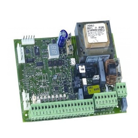
4. ELECTRICAL CONNECTIONS MOTOR THRUST BEAM BREAKING CAPACITOR 10 11 12 13 16 17 24Vdc MOTOR To connect the photocells and 230Vac max 60W safety devices, 230Vac consult paragraph 50Hz 4.1. OPEN STOP Fig. 2 CLOSE EMERGENCY 4.1. CONNECTION OF PHOTOCELLS AND SAFETY DEVICES Connection of two pairs of closing photocells Before you connect the photocells (or other devices) we advise you to select the type of operation according to the movement zone they have to protect. - Page 5 Connection of one safety device (teminals 10-11-19) - Negative contact for feeding accessories 24 Vdc (terminals 12-13) - Positive contact for feeding accessories 10 11 12 13 16 17 Max. load of accessories: 500 mA. To calculate absorption values, refer to the instructions for individual accessories.
-
Page 6: Level Programming
Insert and remove the boards ONLY after cutting Condo Automatic power. Faac-City (traffic bollard logic) Dead-man Remote An example of a 624BLD radio accessory connection Custom RP / RP2 PAUSE TIME: This operates only if an automatic logic was selected. Can be adjusted from in one second steps. - Page 7 The following table indicates the sequence of functions accessible Display Function Default in 2 LEVEL PROGRAMMING: LEVEL PROGRAMMING LOOP 2: If you activate this function, the loop con- nected to Loop2 input will have the SAFETY Display Function Default /CLOSE function, i.e. it will operate as SAFETY during the closing stage, and will command MAXIMUM TORQUE AT THRUST: CLOSE to the board at release.
- Page 8 Function Display Function Default Display Default OUTPUT 1 POLARITY: CYCLE PROGRAMMING IN HUNDREDS OF for configuring the output polarity status. THOUSANDS: = N.C. polarity For setting a count-down of the system = N.O. polarity operating cycles. Settable value from (hundreds of thousands of cycles). Note: if the output is set to FAIL-SAFE ( The displayed value is reset as the cycles leave the default value.
- Page 9 Tab. 1/a LOGIC “A” PULSES AUTOMATED SYSTEM OPEN A CLOSE STOP LOOP 1 LOOP 2 STATUS no effect opens and at end opens and closes after CLOSED no effect (opening disabled) no effect of opening closes if no effect pause time released reverses OPENING...
- Page 10 Tab. 1/d LOGIC “P” PULSES AUTOMATED SYSTEM OPEN A CLOSE STOP LOOP 1 LOOP 2 STATUS opens and at end no effect CLOSED opens no effect no effect of opening closes if no effect (opening disabled) released closes immediately closes immediately OPENING no effect stops operation...
- Page 11 Tab. 1/g LOGIC “CA” PULSES AUTOMATED SYSTEM OPEN A CLOSE STOP LOOP 1 LOOP 2 STATUS opens and at end no effect opens and closes after CLOSED no effect no effect of opening closes if no effect pause time (opening disabled) released closes immediately closes immediately...
- Page 12 Les descriptions et les illustrations du présent manuel sont fournies à titre indicatif. FAAC se réserve le droit d’ap- porter à tout moment les modifications qu’elle jugera utiles sur ce produit tout en conservant les caractéristiques essentielles, sans devoir pour autant mettre à...
Need help?
Do you have a question about the 624BLD and is the answer not in the manual?
Questions and answers