Advertisement
Quick Links
1. WARNINGS
Before attempting any work on the electronic equipment
(connections, maintenance), always turn off power.
- Install, upstream of the system, a differential thermal breaker
with adequate tripping threshold.
- Always separate power cables from control and safety cables
(push-button, receiver, photocells, etc.). To avoid any electrical
disturbance, use separate sheaths or a screened cable (with
the screen earthed).
2. TECHNICAL SPECIFICATIONS
Power supply voltage
Absorbed power
Motor max. load
Accessories max. current
Enviroment temperature
Fuses
F1 = 6.3A-250V F2 = self-resetting
Operating logics
Self-learning (0-10 min in 2.5 sec steps)
Work time (time-out)
Self-learning (0-5 min in 1.5 sec steps)
Pause time
Terminal board inputs
Terminal board outputs
and power supply to accessories
Operation for barrier or up-and-over
Programmable functions
Functions through learning
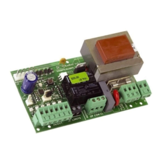
3. LAYOUT AND COMPONENTS
F2
J2
RADIO-DECODER
J2
Led
SW1
DL1
J3
OPTION
J7 OPEN
596
J7
615
OP-A
CLOSE
STOP
SAFE
FCA
FCC
Led
-
+
OPEN
CL
STOP
SAFE
J6
J9
7
J1
J9
J6
1
J1
IN/OUT
FCA
FCC
Description of components
J1
inputs terminal board and power supply to accessories
J2
connector for radio receiver (see Note)
J3
select operation: 596
J4
motor terminal board
JS
230 Vac power supply terminal board
J6
opening limit-switch connector (N.C. contact)
J7
OPEN command connector (for up-and-over)
J8
terminal-board for flashlight and courtesy light
J9
closing limit-switch connector (N.C. contact)
LED
Signalling LEDs
SW1
programming key
TF1
transformer
F1
6.3A- 250 V (motor protection)
F2
self-resetting (accessories protection)
An RP2 type 2-channel receiver can be connected to the
J2 connector, so that the OPEN and CLOSE facilities of the
automated system can be commanded directly with a 2-
channel radio control.
If using a single-channel RP type receiver, only OPEN can be com-
manded.
All manuals and user guides at all-guides.com
CONTROL UNIT 596/615 BPR
230V~ - 50Hz
4 W
800 VA
250 mA
-20°C to +55°C
B/C, B, C, EP , AP , P , A default = EP
Default = 10 min
Default = 15 sec
Open, Close, Stop, Limit-switch,
CL safety devices, Power supply
Motor, flashlight, courtesy light
Logic
Work time, Pause time
TF1
F1
13
J4
J8
J5
10
230 Vac
J8
COM
L
N
J4
Fig. 1
OP
COM
CL
or 615
.
CONNECTIONS
-
+
OP-A
CL
STOP
SAFE
1
2
3
4
5
6
J6
J9
J1
IN/OUT
FCA
FCC
Description of terminal boards
Terminal Description
1
OPEN
2
CLOSE
3
STOP
4
- 24Vdc
5
+ 24Vdc
6
SAFE
7
OP
8
COM
9
CL
10
LAMP
11
COURT.
J5
12
COM
13 - 14
L - N
On boards supplied as a spare part or with operators on
which the limit-switches are optional items, the contacts of
connectors J6 and J9 are short circuited. If sensors are being
installed, eliminate the jumpers and connect the limit-switches
directly or via the specific adaptor, to the connectors. When the
travel-limit sensor is engaged, operation varies according to ope-
ration setting as 596 or 615 (J3).
Opening: immediate stop when sensor is engaged.
Closing: when the sensor is engaged, the operator works for 4 sec in
slow-down and for 1 sec. at standard speed (over-pushing stroke).
Opening and closing: when the sensor is engaged, slow-down is
executed with a duration of half the time at standard speed.
If the travel-limit sensors are not installed, the appliance executes
only the learnt work time (see par.6.2).
7
8
9
10 11 12
13 14
COM
L
OP
COM
CL
230 Vac
230 Vac
max 40W
+6% -10%
M
230 Vac
max 60W
C
Other Safety
Devices
Fig. 2
Device connected
Device with N.O. contact
(see chap. FUNCTION LOGICS)
Device with N.O. contact
(see chap. FUNCTION LOGICS)
Device with N.C. contact which cau-
ses the automated system to lock
Power supply for accessories
Closure safety device with N.C.
contact
(see chap. FUNCTION LOGICS)
Motor opening stage
Motor common contact
Motor closure stage
Output for flashing light
230 Vac max 60W
Output for courtesy light 230
Vac max 40W
timing 90 sec. not modifiable
Common contact for light/flashing light
Board power supply (230Vac)
596
615
N
Advertisement

Related Manuals for FAAC 596 BPR


Summary of Contents for FAAC 596 BPR
- Page 1 All manuals and user guides at all-guides.com CONTROL UNIT 596/615 BPR CONNECTIONS 1. WARNINGS Before attempting any work on the electronic equipment (connections, maintenance), always turn off power. OP-A STOP SAFE - Install, upstream of the system, a differential thermal breaker 10 11 12 13 14 with adequate tripping threshold.
- Page 2 All manuals and user guides at all-guides.com 5. PROGRAMMING THE FUNCTION LOGIC 6.3 PRE-FLASHING To select the function logic, press the SW1 push-button the number If you wish to increase the equipment's safety level, you can activate of times equal to the number of the required logic, irrespective of the the pre-flashing function which enables the flashing lamp to go on current logic and the door status.
- Page 3 73/23/EEC and subsequent amendment 93/68/EEC. 89/336/EEC and subsequent amendment 92/31/EEC and 93/68/ Additional note: This product underwent tests in a typical uniform configuration (all products manufactured by FAAC S.p.A.). Bologna, 01 January 2006 The Managing Director A. Bassi...
Need help?
Do you have a question about the 596 BPR and is the answer not in the manual?
Questions and answers