Viessmann Vitotronic 200 Operating Instructions For The System User
Heat pump control unit
Hide thumbs
Also See for Vitotronic 200:
- User manual ,
- Service instructions manual (336 pages) ,
- Installation and service instructions for contractors (136 pages)

Related Manuals for Viessmann Vitotronic 200


Summary of Contents for Viessmann Vitotronic 200
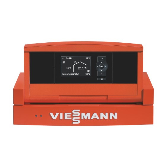
- Page 1 VIESMANN Operating instructions for the system user Heat pump control unit Vitotronic 200, type WO1A VITOTRONIC 200 Please keep safe. 5592 647 GB 8/2010...
- Page 2 Safety instructions For your safety Please follow these safety instructions closely to prevent accidents and mate- rial losses. Safety instructions explained Danger Incorrect work on the system can Danger lead to life-threatening acci- This symbol warns against the dents. risk of injury. Work on electrical equipment must only be carried out by a Please note...
- Page 3 Safety instructions For your safety (cont.) Auxiliary components, spare and wearing parts Please note Components that are not tested with the system may cause sys- tem damage, or may affect its functions. Installation or replacement work must only be carried out by quali- fied personnel.
- Page 4 Index Index Introductory information Device description....................Commissioning..................... Your system is preset at the factory..............Terminology......................Energy saving tips....................Operation Controls........................ 11 ■ Opening the control unit..................11 ■ Programming unit....................14 Menu........................14 How to operate..................... 16 Start-up/shutdown Starting the heat pump..................19 Stopping the heat pump..................
- Page 5 Index Index Setting the time program..................35 ■ Operating status for DHW heating..............37 ■ Start optimisation....................37 ■ Stop optimisation....................37 ■ DHW heating outside the time program............38 Setting the time program for the DHW circulation pump........38 ■...
- Page 6 Index Index (cont.) Menu overview..................... 56 ■ Standard menu ....................56 ■ Extended menu....................57 Terminology......................59 Keyword index....................66...
-
Page 7: Device Description
Introductory information Device description Subject to the type of heat pump and ■ DHW heating: accessories installed, your heating sys- DHW heating using an external DHW tem may be equipped as follows: cylinder, and control of a DHW circu- ■ Heating circuits: lation pump are possible. - Page 8 Introductory information Your system is preset at the factory (cont.) Your heating system is therefore ready Frost protection for use: ■ Frost protection for your heat pump, the DHW cylinder and any heating Central heating/Central cooling water buffer cylinder that may be ■...
-
Page 9: Energy Saving Tips
Introductory information Energy saving tips Utilise the setting options offered by the ■ For central heating/cooling, select the heat pump control unit and the remote operating program that meets your control (if installed): current requirements: ■ Never overheat your rooms. Every –... - Page 10 Introductory information Energy saving tips (cont.) Further recommendations: ■ Correct ventilation. Briefly open windows fully and at the same time close thermostatic valves (if no domestic ventilation system is installed). ■ Close roller shutters (if installed) at dusk. ■ Set thermostatic valves correctly. ■...
-
Page 11: Operation
Operation Controls You can change all heat pump control Note unit settings centrally at the program- The programming unit can be placed in ming unit. a wall mounting base. This is available If remote control units are installed in as an accessory. Ask your heating con- your rooms, you can also adjust the set- tractor for more information. - Page 12 Operation Controls (cont.) Control unit on top of the heat pump A Button for changing the angle C ON indicator (green) B Programming unit D Fault indicator (red)
- Page 13 Operation Controls (cont.) Control unit mounted on the wall A ON/OFF switch C ON indicator (green) B Programming unit D Fault indicator (red)
-
Page 14: Programming Unit
Operation Controls (cont.) Programming unit Flow temperature 40°C Heating/cooling Solar energy Information Select with Takes you to the previous step in OK Confirms your selection or saves the menu or cancels a setting that the setting. has been started. Calls up the help text relevant to the Cursor keys selected menu point. - Page 15 Operation Menu (cont.) Standard menu Flow temperature 40°C Heating/cooling Solar energy Information Select with In the standard menu, you can adjust ■ Starting manual mode and scan the settings used most fre- ■ Scanning information, warning and quently: fault messages ■...
-
Page 16: How To Operate
Operation Menu (cont.) Extended menu Menu Heating/cooling System Information Select with In the extended menu, you can adjust Call up the extended menu as follows: and scan the settings from the control ■ If the screen saver is active: unit's range of functions used less fre- Press any key and then quently, e.g. - Page 17 Operation How to operate (cont.) Press OK. This takes you to the standard menu (see page 15). 40 °C Flow temperature Heating/cooling Solar energy Information Select with A Dialogue line The selected menu option is highlighted The following example shows the setting in white.
- Page 18 Operation How to operate (cont.) Flow temperature 40 °C Heating/cooling Solar energy Information Select with Heating circuit 1 Ù Ú Htg circuit selection Ù Ú Ù Ú Set room temp. Ú 20 °C Heating program Heating circuit 2 ß Party mode Economy mode Select with Was selected...
-
Page 19: Starting The Heat Pump
Start-up/shutdown Starting the heat pump The heat pump control unit may look dif- ferent depending on the type of heat pump. Control unit at the front of the heat pump Flow temperature 40℃ Heating/cooling Solar energy Information Select with A ON/OFF switch " " C ON indicator (green) D Fault indicator (red) B Programming unit... - Page 20 Start-up/shutdown Starting the heat pump (cont.) Control unit on top of the heat pump r l a u f t i z u r a t / K ü h l u s s e l a r I n f e r g °...
- Page 21 Start-up/shutdown Starting the heat pump (cont.) Control unit mounted on the wall A ON/OFF switch " " C ON indicator (green) D Fault indicator (red) B Programming unit 1. Switch ON the power supply, e.g. at 2. Switch the ON/OFF switch " " ON. a separate MCB/fuse or a main iso- After a short time, the standard menu lator.
-
Page 22: With Frost Protection Monitoring
Start-up/shutdown Stopping the heat pump With frost protection monitoring For every heating/cooling circuit, select Note the operating program "Standby The circulation pumps are briefly started mode". every 24 hours to prevent them from seizing up. Standard menu 1. "Heating" or "Heating/cooling" Ending the operating program 2. - Page 23 Start-up/shutdown Stopping the heat pump (cont.) 2. Isolate the heat pump from the power supply, e.g. at a separate MCB/fuse or a main isolator. Please note If outside temperatures below 3 °C are expected, take appropriate measures to pro- tect the heat pump and the heating system from frost.
- Page 24 Central heating/cooling Required settings If you want central heating or cooling, ■ Have you set the correct operating check the following points: program? ■ Have you selected the heating/cooling For settings, see page 26. circuit? ■ Have you set the required time pro- For settings, see chapter "Selecting gram? the heating/cooling circuit".
-
Page 25: Heating Circuit
Central heating/cooling Selecting the heating/cooling circuit (cont.) Heating circuit 1 Htg circuit selection Ù Ù Ú Ú Set room temp. 21 °C Heating program Heating circuit 2 Ú ß Party mode Economy mode Select with Was selected Factory-set designation of the heating/ Note cooling circuits: The abbreviations "HC1", "HC2",... - Page 26 Central heating/cooling Setting the room temperature (cont.) 4. "Set red. room temp" Central heating with this temperature: 5. Set the required value. ■ Active in the time program in operating status "Reduced" (see page 28). ■ In the holiday program (see page 32).
- Page 27 Central heating/cooling Setting a time program (cont.) Note 7. Set the start and end points for the This setting is suitable for operation relevant time phase. The length of the with underfloor heating systems (see white bar on the time chart is adapted page 9).
- Page 28 Central heating/cooling Setting a time program (cont.) Example: The display shows the selected time You want to set the same time program phase "- - : - -". for every day except Monday: Select the period "Monday–Sunday" Heating/cooling Mo-Su and set the time program. Then select "Monday"...
-
Page 29: Changing The Heating Curve
Central heating/cooling Setting a time program (cont.) Your heating contractor may have adjus- ted these values. Enabling an electric booster heater If the heat pump on its own cannot ach- Extended menu ieve the selected set room temperature, an instantaneous heating water heater (if 2. - Page 30 Central heating/cooling Changing the heating curve (cont.) Depending on various outside tempera- Heating curve tures (shown on the horizontal axis), the 100 °C assigned set flow temperatures for the heating circuit are highlighted in white. 55 °C 49 °C 43 °C 35 °C Note Slope...
-
Page 31: Selecting Party Mode
Comfort and energy saving functions Selecting party mode With this comfort function, you can 3. "Party mode" change the room temperature of a heat- ing/cooling circuit for a few hours, e.g. if Heating circuit 1 Ù Ú guests stay a little longer in the evening. Set room temp. -
Page 32: Selecting Economy Mode
Comfort and energy saving functions Selecting economy mode To save energy, you can reduce the Heating circuit 1 Ù Ú room temperature in standard heating Set room temp. mode, for example, if you leave the house for a few hours. Heating program â... - Page 33 Comfort and energy saving functions Selecting the holiday program (cont.) Extended menu: 2. "Heating" or "Heating/cooling" 3. "Holiday program" Holiday program Leaving date: Date Tu 24.02.2009 Return date: Date We 25.02.2009 Change with 4. Set the required departure and return dates.
- Page 34 DHW heating Required settings If you want DHW heating, check the fol- ■ Have you set the required time pro- lowing points: gram? ■ Have you selected the required set For settings, see page 35. DHW temperature? For settings, see page 34. ■...
- Page 35 DHW heating Setting the operating program (cont.) "Only DHW" (no central heating/cool- 3. "Cooling circuit SKK" ing) 4. "Heating program" 5. "Cooling" (with central cooling) "Standby mode" (only frost protec- tion, see page 30) "Only DHW" (without central cooling) For the separate cooling circuit: "Standby mode"...
- Page 36 DHW heating Setting the time program (cont.) 6. Set the start and end points for the Example: relevant time phase. The length of the You want to set the same time program white bar on the time chart is adapted for every day except Monday: accordingly (see the following exam- Select the period "Monday–Sunday"...
-
Page 37: Start Optimisation
DHW heating Setting the time program (cont.) Operating status for DHW heating The different operating statuses indicate "Temp. 2" how the DHW cylinder is heated. The entire volume in the DHW cylinder is "Standard" heated to the "Set DHW temperature 2"... -
Page 38: Dhw Heating Outside The Time Program
DHW heating Setting the time program (cont.) Extended menu: 2. "DHW" 3. "Stop optimisation" DHW heating outside the time program You can start DHW heating immediately DHW heating with the comfort func- either with the "1x DHW heating" or with tion "Party mode"... - Page 39 DHW heating Setting the time program for the DHW… (cont.) At the factory, no time phases for the Example: DHW circulation pump are set, i.e. the ■ Time program for Monday ("Mo-Su") DHW circulation pump is switched off. ■ Time phase !: ■...
- Page 40 DHW heating Setting the time program for the DHW… (cont.) The display shows the selected time phase "- - : - -". Time prog. DHW circ. Mo-Su 8 10 12 14 16 18 20 22 24 ? - -:- - - -:- - §...
-
Page 41: Switching Off Dhw Heating
DHW heating Switching off DHW heating You do not want to heat DHW or heat For the separate cooling circuit: or cool your rooms. Extended menu Standard menu 1. "Heating" or "Heating/cooling" 2. "Heating/cooling" 2. Where appropriate, select the heat- 3. - Page 42 Heating water buffer cylinder Setting a time program ■ The time program for the heating 6. Set the start and end points for the water buffer cylinder is made up of relevant time phase. The length of the time phases. Set an operating status white bar on the time chart is adapted for each time phase ("Top", "Stand- accordingly (see the following exam-...
- Page 43 Heating water buffer cylinder Setting a time program (cont.) Then select "Monday" and set the time The display shows the selected time program for this. phase "- - : - -". Note Time prog. buffer cyl. Mo-Su If you want to cancel the setting early, press repeatedly until the required display appears.
-
Page 44: Setting The Display Contrast
Further adjustments Setting the display brightness If you would like the texts in the menu to 3. "Brightness" be more clearly legible, change the 4. "Control" or "Screen saver" brightness for "Control". 5. Set the required brightness. You can also alter the screen saver brightness. -
Page 45: Language Selection
Further adjustments Entering heating circuit designations (cont.) The menu shows "Apartment" for heat- Heating circuit 2 ing circuit 2. Apartment Apartment Apartment Ù Ú Set room temp. 22 °C Adopted Heating program ß Party mode Economy mode Select with Setting the time and date The time and date are factory set. - Page 46 Further adjustments Restoring factory settings You can restore the factory settings of all The following settings and values are modified values for every heating/cool- reset: ing circuit, DHW heating and other sys- ■ "Set DHW temperature" tem settings separately. ■ "Set DHW temperature 2" ■...
-
Page 47: Scanning Information
Scanning Scanning information Subject to the components connected Extended menu and settings made, you can scan current temperatures and settings, time pro- 2. "Information" grams and operating states. 3. Select the category. You can scan information in the standard 4. Select the required scan. menu and in the extended menu. -
Page 48: Scanning Messages
Scanning Scanning information (cont.) "HP2" Hours run, heat pump stage 2 Daily log "AC" Hours run in active cooling CW T.in T.out HP1 mode "NC" Hours run with the natural cool- ing function Note This information will be retained even if Select with the heat pump control unit develops a fault. - Page 49 Scanning Scanning messages (cont.) Pressing ? provides you with the fol- ■ If you have connected up signalling lowing information regarding the equipment (e.g. a buzzer) for fault selected message: messages, this is deactivated when ■ Date and time when the message the fault message is acknowledged.
- Page 50 Manual mode Manual mode In manual mode, central heating and DHW heating are implemented inde- pendently of the time programs: ■ Unregulated heating with a set flow temperature of 45 °C. ■ DHW heating with "Set DHW temper- ature 2" (see page 34). ■...
-
Page 51: Rooms Are Too Cold
What to do if... Rooms are too cold Cause Remedy The heat pump is switched off. ■ Switch the ON/OFF switch " " ON (see diagrams from page 19). ■ Switch ON the main isolator, if installed (outside the boiler room). ■... -
Page 52: There Is No Hot Water
What to do if... There is no hot water Cause Remedy The heat pump is off. ■ Switch the ON/OFF switch " " ON (see diagrams from page 19). ■ Switch ON the main isolator, if installed (outside the boiler room). ■... -
Page 53: "External Program" Is Displayed
What to do if... "Power-OFF C5" is displayed Cause Remedy This message is displayed whilst the No measures required. power supply is blocked by the power The heat pump restarts automatically with supply utility. the selected operating program as soon as the power supply utility restores the power supply. -
Page 54: Inspection And Maintenance
Maintenance Maintenance Cleaning All equipment can be cleaned with a commercially available domestic clean- ing agent (non-scouring). Clean the sur- face of the programming unit with a microfibre cloth. Inspection and maintenance The inspection and maintenance of a heating system is specified by the Energy Sav- ing Order [EnEV - Germany] and the DIN 4755, DIN 1988-8 and EN 806 stand- ards. - Page 55 Appendix Refrigerant This appliance contains fluorinated The refrigerants used have the following hydrocarbons (refrigerant) included in greenhouse potential: the Kyoto Protocol. ■ R 134A: 1300 The type plate indicates the type of ■ R 410A: 1890 refrigerant used in the heat pump. ■...
- Page 56 Appendix Menu overview Standard menu...
- Page 57 Appendix Menu overview (cont.) Extended menu 16 A Continued in the following diagram...
- Page 58 Appendix Menu overview (cont.) Information System Heating circuit 1 Outside temperature Heating circuit 2 Common flow temp. Heating circuit 3 Operating status system Cooling circuit SKK Heating season Cooling period Solar Buffer cylinder Heat pump Op. status buffer cylinder Daily log Time prog.
- Page 59 Appendix Terminology Setback mode (reduced heating ■ "Only DHW" mode) DHW is heated but central heating is not active. See "Reduced heating mode". ■ "Standby mode" Frost protection for the heat pump, the Standby mode DHW cylinder and heating water buffer cylinder (accessory) is active;...
- Page 60 Appendix Terminology (cont.) Extension kit for heating circuit with In order to guarantee sufficient heat at mixer any outside temperature, the conditions of your building and your heating system Assembly (accessory) for controlling a must be taken into consideration. For heating circuit with mixer.
- Page 61 Appendix Terminology (cont.) Slope Outside temperature in °C For outside temperature −14 °C: A Underfloor heating, slope 0.2 to 0.8 B Low temperature heating, slope 0.8 to 1.6 Factory settings: slope = 0.6 and level =...
- Page 62 Appendix Terminology (cont.) Outside temperature in °C A Changing the slope: C Changing the standard room tem- The gradient of the heating curves perature (set value): changes. The heating curves are offset along B Changing the level: the "Set room temperature" axis. The heating curves are shifted in parallel in a vertical direction.
- Page 63 Appendix Terminology (cont.) Heating/cooling circuits and separate Actual temperature cooling circuit Current temperature at the time of the ■ Heating circuit scan, e.g. actual DHW temperature. A heating circuit is a sealed circuit between the heat pump and consum- Cooling functions ers (radiators), in which the heating water circulates.
- Page 64 Appendix Terminology (cont.) Air/water heat pumps: Natural cooling ■ Natural cooling is not available. See chapter "Cooling functions". ■ "Active cooling" Cooling is effected by reversing the Standard heating/cooling mode heat pump operation. A high cooling capacity is available. When you are at home during the day, you can heat or cool the rooms in stand- Information on active cooling ard heating or cooling mode.
- Page 65 Appendix Terminology (cont.) Reduced room temperature Cylinder primary pump When you are out or during the night, set Circulation pump for heating the DHW in the reduced room temperature (see the DHW cylinder. page 25). See also "Reduced heating mode". Drinking water filter Safety valve A device that removes solids from the...
- Page 66 Keyword index Keyword index Cooling circuit........63 Active cooling......59, 63, 64 Cooling curve........60 Active cooling function Cooling function ■ Blocking..........30 ■ Active cooling....7, 30, 63, 64 ■ Enable..........30 ■ Natural cooling......7, 30, 64 Active cooling functions Cooling limit........64 ■ Explanation........63 Cooling mode Active cooling mode.....30, 59 ■...
- Page 67 Keyword index Keyword index (cont.) Display ■ Setting the brightness.....44 Glossary..........59 ■ Setting the contrast......44 Greenhouse potential......55 Drinking water filter......65 Heating circuit........63 Economy function Heating circuit designations....44 ■ Economy mode.......32 Heating circuit pump......63 ■ Holiday program......32 Heating circuit with mixer....60 Economy mode........32 Heating curve Enable...
- Page 68 Keyword index Keyword index (cont.) Information Natural cooling......63, 64 ■ Scanning.........47 Natural cooling functions ■ Solar thermal system......47 ■ Explanation........63 Inspection...........54 No hot water........52 Instantaneous heating water heater...22 Note ■ For central heating......29 ■ Acknowledging.......48 ■ For DHW heating......40 ■ Calling up........49 ■...
- Page 69 Keyword index Keyword index (cont.) Programming unit.......11 Screen saver........14, 16 Pump Secondary pump........65 ■ Cylinder heating......65 Selecting the cooling circuit....24 ■ DHW..........65 Selecting the heating circuit....24 ■ DHW circulation......65 Selecting the separate cooling circuit 24 ■ Heating circuit.........63 Separate cooling circuit....24, 63 ■...
- Page 70 Keyword index Keyword index (cont.) Starting Time phases ■ Central heating/cooling....24 ■ Central heating/cooling....26 ■ DHW heating........34 ■ DHW circulation pump....38 ■ Frost protection monitoring.....22 ■ DHW heating........35 ■ Heat pump........19 ■ Heating water buffer cylinder..42 Starting standby mode.......22 Time program Start optimisation......35, 37 ■...
-
Page 72: Your Contact
Contact your local contractor if you have any questions regarding the maintenance and repair of your system. You may, for example, find local contractors on the internet under www.viessmann.com. Viessmann Werke GmbH&Co KG Viessmann Limited D-35107 Allendorf Hortonwood 30, Telford...
Need help?
Do you have a question about the Vitotronic 200 and is the answer not in the manual?
Questions and answers