Viessmann VITOTRONIC 200 Installation And Service Instructions Manual
Type ho1b & mw2b, digital boiler control unit & weather-compensated, digital cascade control unit
Hide thumbs
Also See for VITOTRONIC 200:
- User manual ,
- Service instructions manual (336 pages) ,
- Installation and service instructions for contractors (136 pages)
Table of Contents
Advertisement
Installation and Service
Instructions
for use by heating contractor
Vitotronic 200, Type HO1B
Digital boiler control unit
Vitotronic 300-K, Type MW2B
Weather-compensated, digital cascade control unit
VITOTRONIC
VITOTRONIC
Certified as a component
part for Viessmann boilers
5693 976 - 02 07/2014
200
r
300-K
r
Vitotronic 200
Vitotronic 300-K
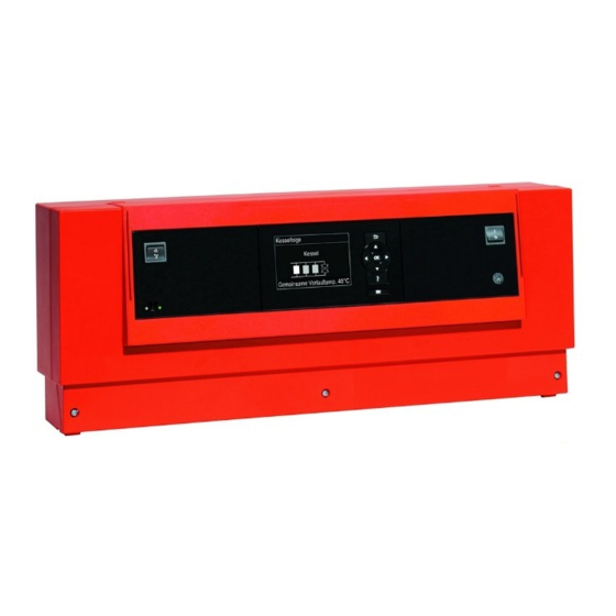
Product may not be exactly as shown
IMPORTANT
Read and save these instructions
for future reference
.
Please file in Service Binder
Advertisement
Table of Contents

Related Manuals for Viessmann VITOTRONIC 200


Summary of Contents for Viessmann VITOTRONIC 200
- Page 1 Installation and Service Instructions for use by heating contractor Vitotronic 200, Type HO1B Digital boiler control unit Vitotronic 300-K, Type MW2B Weather-compensated, digital cascade control unit VITOTRONIC VITOTRONIC 300-K Vitotronic 200 Vitotronic 300-K Product may not be exactly as shown...
-
Page 2: Safety, Installation And Warranty Requirements
General Vitotronic 200 and 300-K Installation and Service Safety, Installation and Warranty Requirements Please ensure that these instructions are read and understood before commencing installation. Failure to comply with the instructions listed below and details printed in this manual can cause product/property damage, severe personal injury, and/or loss of life. -
Page 3: Table Of Contents
Table of Contents Vitotronic 200 and 300-K Installation and Service Page General Safety, Installation and Warranty Requirements....2 Product documentation...........2 Licensed professional heating contractor....2 Advice to owner............2 Warranty...............2 Operating and Service Documentation......2 Preparing for Installation System Example............5 Installation Sequences Preparing Boilers for Cascade Mode......7 Overview of Electrical Connections, Vitotronic 300-K...11... - Page 4 Table of Contents Vitotronic 200 and 300-K Installation and Service Page Coding 1 Calling Up Coding Level 1 - Vitotronic 200....32 “General” Group............33 “Boiler” Group............33 Calling Up Coding Level 1 - Vitotronic 300-K....34 “General” Group............36 “Cascade” Group............36 “DHW” Group............36 “Solar” Group............37 “Heating Circuit 1”, “Heating Circuit 2”,...
-
Page 5: System Example
Preparing for Installation Vitotronic 200 and 300-K Installation and Service System Example Multi boiler system with several heating circuits with mixing valve and low loss header (with/without DHW heating) Note: This scheme is a basic example without shut-off valves or safety equipment. - Page 6 Preparing for Installation Vitotronic 200 and 300-K Installation and Service System Example (continued) Vitotronic 200 (set codes at every Vitotronic 200 - boiler control) Switching mode from standalone/weather compensated control to constant temperature control (see page 10). Required coding Group...
-
Page 7: Preparing Boilers For Cascade Mode
Installation Sequence Vitotronic 200 and 300-K Installation and Service Preparing Boilers for Cascade Mode IMPORTANT The following procedure must be done on each boiler connected to the Vitotronic 300-K. Removing the front enclosure panel 1. Remove the external accessories connection box cover. - Page 8 Installation Sequence Vitotronic 200 and 300-K Installation and Service Preparing Boilers for Cascade Mode (continued) Installation of the communication module The communication module is part of the standard delivery. 1. Installing the cascade communication module to the Vitotronic 200. Note: The cascade communication module must be fitted into every Vitotronic 200.
- Page 9 Installation Sequence Vitotronic 200 and 300-K Installation and Service Preparing Boilers for Cascade Mode (continued) Closing the control unit cover 1. Install the cover onto the control board. 2. Flip the control board back into position. 3. Secure the locking tabs as shown.
- Page 10 Installation Sequence Vitotronic 200 and 300-K Installation and Service Preparing Boilers for Cascade Mode (continued) IMPORTANT The following procedure must be done to configure each boiler for constant temperature control (cascade control) mode. 1. Turn on the boiler and set the language then press ‘OK’.
-
Page 11: Overview Of Electrical Connections, Vitotronic 300-K
Installation Sequence Vitotronic 200 and 300-K Installation and Service Overview of Electrical Connections, Vitotronic 300-K With accessory module Legend PCB, extension for heating circuits 2 and 3 (accessory) Main PCB 120V~ ? M2/M3 Supply temperature sensor sÖA1 Heating circuit pump sÖ... - Page 12 Installation Sequence Vitotronic 200 and 300-K Installation and Service Overview of Electrical Connections, Vitotronic 300-K (continued) Legend A Vitotronic 300-K B Din rail...
-
Page 13: Mounting The Control Unit
Installation Sequence Vitotronic 200 and 300-K Installation and Service Mounting the Control Unit 1. Fasten metal backplate onto mounting surface with four fasteners. 2. Position midplate between backplate and connection enclosure. 3. Install midplate and connection enclosure onto backplate. 4. Fasten connection enclosure and midplate onto backplate with two fasteners. -
Page 14: Inserting Cables/Leads And Applying Strain Relief
Installation Sequence Vitotronic 200 and 300-K Installation and Service Inserting Cables/Leads and Applying Strain Relief Run the cables from the connection enclosure into the control unit. Apply strain relief to cables. Cables with moulded strain relief clamp: Connect cable and strain relief clamp. -
Page 15: Connecting Pumps
Installation Sequence Vitotronic 200 and 300-K Installation and Service Connecting Pumps Pumps 120V Legend Available pump connections A120V outputs sÖM1/A1 High temperature circuit pump/ B To the control unit primary store pump Rated current: 2 A~ sÖM2 Heating circuit 2 pump... -
Page 16: External Connection
Installation Sequence Vitotronic 200 and 300-K Installation and Service 120V External Connection 120V pumps with an amperage draw of <2FLA A Din rail B Pump 120V pumps with an amperage draw of >2FLA Contactor specification 120VAC 1A A Din rail... -
Page 17: Connecting Actuators
Installation Sequence Vitotronic 200 and 300-K Installation and Service Connecting Actuators Legend Legend A 24V Mixing Valve Adaptor A 120V Mixing Valve Adaptor B DIN Rail (in junction box) B DIN Rail (in connection enclosure) C 24V Valve Actuator C 120V Valve Actuator... -
Page 18: Connecting The Central Fault Message Facility
Installation Sequence Vitotronic 200 and 300-K Installation and Service Connecting the Central Fault Message Facility Rated voltage 120V~ Rated current max. 2 A~ External Demand via Switching Contact Connection options: Connection at plug aVH Extension EA1 (accessory, see page 90) Connection Note: ‘Live’... -
Page 19: External Demand Via 0-10V Input
Installation Sequence Vitotronic 200 and 300-K Installation and Service External Demand via 0 – 10V Input Demand for a system supply temperature set value. Connection to input 0 -10V at extension EA1 (accessory). See page 90. 0 - 1V no default set supply temperature set value 50°... -
Page 20: External "Mixing Valve Closed"/"Mixing Valve Open
Installation Sequence Vitotronic 200 and 300-K Installation and Service External “Mixing Valve Close”/”Mixing Valve Open” Connection at plug avD The mixing valves are opened A or closed B when the contact is closed. Note: ‘Live’ contacts lead to short circuits or phase failure. -
Page 21: Making The Lon Connection
Installation Sequence Vitotronic 200 and 300-K Installation and Service External Heating Program Changeover (continued) Preselected heating program (Contact open) Coding Changed heating program (Contact closed) Central heating D5:0 Permanent operation with reduced room OFF/DHW OFF (factory set condition) temperature/ DHW OFF... - Page 22 Installation Sequence Vitotronic 200 and 300-K Installation and Service Making the LON Connection (continued) Connection with on-site cable and LON plug The line may be up to ≤ 3000 ft. (900 m) (with LON plug) Legend A Control unit or Vitocom...
-
Page 23: Power Supply
Installation Sequence Vitotronic 200 and 300-K Installation and Service Power Supply Legend L: Line N: Neutral G: Ground 1. Ensure that the main power supply to the control contains overcurrent protection with a minimum A Power supply 120VAC, 1PH, 60Hz, provide rating of 6A and 2-pole disconnect. -
Page 24: Fitting The Front Part Of The Control Unit
Installation Sequence Vitotronic 200 and 300-K Installation and Service Fitting the Front Part of the Control Unit Legend Note: Route the ribbon cable through retainer A. A Cable retaining tab Opening the Control Unit... -
Page 25: Changing The Language
Commissioning Vitotronic 200 and 300-K Installation and Service Changing the Language At the commissioning stage, the display is in German. 1. “Sprache” (Language) Deutsch DE (German) 2. Select the required language with 3. Accept by pressing OK. To change the language Extended menu: 2. - Page 26 Code “9C:20” Code “9C:20” Flue gas cascade with positive pressure Set code “7E:1” Prior to coding the Vitotronic 200, ensure the boiler is in cascade mode. Refer to page 10. For the Vitotronic 200, see boiler Service Instructions 1. Press and OK for approximately 4 seconds.
-
Page 27: Connecting The Control Unit To The Lon System
Commissioning Vitotronic 200 and 300-K Installation and Service Connecting the Control Unit to the LON System Carrying out a LON participant check H See also chapter “Configuring multi boiler systems”. Communication with the system devices connected to the H Vitotronic 300-K and 200-H: fault manager is tested by means of a participant check. -
Page 28: Matching Coding Addresses To The System Version
Commissioning Vitotronic 200 and 300-K Installation and Service Matching Coding Addresses to the System Version In code 1, set the following coding addresses: Check the following coding addresses and adjust “00” System scheme accordingly in Code 2: “35” Number of boilers in the cascade “39”... -
Page 29: Checking Outputs Actuators And Sensors
Commissioning Vitotronic 200 and 300-K Installation and Service Checking Outputs Actuators and Sensors Testing the relay – Vitotronic 300-K 1. Press OK and simultaneously for approx. 4 sec. 2. “Actuator test” The following relay outputs can be controlled subject to system design:... - Page 30 Commissioning Vitotronic 200 and 300-K Installation and Service Checking Outputs Actuators and Sensors (continued) Settings in the factory set condition: Slope H Slope = 1.4 H Shift = 0 The heating curves illustrate the relationship between the outside temperature and the boiler water or supply temperature.
- Page 31 Commissioning Vitotronic 200 and 300-K Installation and Service Checking Outputs on Actuators and Sensors (continued) Adjusting the set room temperature 79 °F 230 °F (26 °C) (110 °C) Standard room temperature 68 °F (20 °C) Example 1: Adjustment of the standard room temperature from 68 to 79°...
-
Page 32: Calling Up Coding Level 1 - Vitotronic 200
Code 1 Vitotronic 200 and 300-K Installation and Service Calling up Coding Level 1 – Vitotronic 200 Prior to coding the Vitotronic 200, ensure the boiler is in cascade mode. Refer to page 10. For the Vitotronic 200, see boiler Service Instructions 1. -
Page 33: General" Group
Code 1 Vitotronic 200 and 300-K Installation and Service “General” Group Coding Coding in the factory setting Possible change System design (boiler connected to cascade) 00:0 00:1 Do Not Adjust 00:10 Lock out controls 8F:0 Operation in the 8F:1 Operation in standard menu standard menu and extended menu blocked. -
Page 34: Calling Up Coding Level 1 - Vitotronic 300-K
Code 1 Vitotronic 200 and 300-K Installation and Service Calling up Coding Level 1 – Vitotronic 300-K 1. Press 2. Use to scroll to serviceand select with OK. 3. Use to scroll to service functionsand select with OK. 3. Use to scroll to multi-boiler systemand select... -
Page 35: General" Group
Code 1 Vitotronic 200 and 300-K Installation and Service “General” Group Coding Coding in the factory set condition Possible change System design 00:1 System version 1: 00:2 For system schemes, see the following table: One heating circuit without mixing valve A1... -
Page 36: Cascade" Group
Code 1 Vitotronic 200 and 300-K Installation and Service “Cascade” Group Coding Coding in the factory set condition Possible change Number of boilers in cascade 35:4 4 boilers connected to the Vitotronic 300-K 35:1 1 to 8 boilers connected to the Vitotronic 300-K 35:8 Min. -
Page 37: Solar" Group
Code 1 Vitotronic 200 and 300-K Installation and Service “Solar” Group Note: The solar group is only displayed if a solar control module, type SM1, is connected. Coding Coding in the factory set condition Possible change Speed control solar circuit pump... -
Page 38: Heating Circuit 1, Heating Circuit 2, Heating Circuit 3" Group
Code 1 Vitotronic 200 and 300-K Installation and Service “Heating Circuit 1, Heating Circuit 2, Heating Circuit 3” Group Coding Coding in the factory set condition Possible change Priority DHW heating A2:2 A2:0 Without DHW tank priority applicable to heating circuit... - Page 39 Code 1 Vitotronic 200 and 300-K Installation and Service “Heating Circuit 1, Heating Circuit 2, Heating Circuit 3” Group (continued) Coding in the factory set condition Possible change Extended economy function mixing valve A7:0 Without mixing valve economy function A7:1...
- Page 40 Code 1 Vitotronic 200 and 300-K Installation and Service “Heating Circuit 1, Heating Circuit 2, Heating Circuit 3” Group (continued) Coding in the factory set condition Possible change Min. supply temperature heating circuit C5:20 Electronic minimum supply temperature C5:1 Minimum limit adjustable from 34 to 260° F limit (1 to 127°...
- Page 41 Code 1 Vitotronic 200 and 300-K Installation and Service “Heating Circuit 1, Heating Circuit 2, Heating Circuit 3” Group (continued) Coding in the factory set condition Possible change Start temperature raising F8:-5 Temperature limit for terminating reduced mode F8:+10 Temperature limit adjustable from 23°...
-
Page 42: Calling Up Coding Level 2 - Vitotronic 200
Code 2 Vitotronic 200 and 300-K Installation and Service Calling up Coding Level 2 – Vitotronic 200 Prior to coding the Vitotronic 200, ensure the boiler is in cascade mode. Refer to page 10. For the Vitotronic 200, see boiler Service Instructions 1. -
Page 43: General" Group
Code 2 Vitotronic 200 and 300-K Installation and Service “General” Group Select “General” Coding Coding in the factory setting Possible change 00:0 00:1 Do Not Adjust 00:10 11:≠ 9 No access to the coding 11:9 Access open to the coding... - Page 44 Code 2 Vitotronic 200 and 300-K Installation and Service “General” Group Coding Coding in the factory setting Possible change 3B:0 Function input DE2 at extension 3B:1 Function input DE2: Heating EA1: Not assigned program - changeover. 3B:2 Function input DE2: External demand with set supply temperature.
- Page 45 Code 2 Vitotronic 200 and 300-K Installation and Service “General” Group Coding Coding in the factory setting Possible change 53:1 53:0 Function connection sK of the Function connection sK: Central internal extension: fault message. DHW circulation pump 53:2 Function connection sK: External heating circuit pump (heating circuit 1).
-
Page 46: Calling Up Coding Level 2 - Vitotronic 300-K
Code 2 Vitotronic 200 and 300-K Installation and Service Calling up Coding Level 2 – Vitotronic 300-K Note: H In coding level 2, all codes are accessible, including the codes from coding level 1. H Codes that have no function due to the heating system equipment level or the setting of other codes are not displayed. -
Page 47: General" Group
Code 2 Vitotronic 200 and 300-K Installation and Service “General” Group Coding Coding in the factory set condition Possible change 00:1 System version 1: 00:2 For system schemes, see the following table: One heating circuit without mixing valve A1 (heating circuit 1), without DHW heating... - Page 48 Code 2 Vitotronic 200 and 300-K Installation and Service “General” Group (continued) Coding in the factory set condition Possible change 50:10 Start integral threshold for external heat 50:1 Start integral threshold for external heat source source set to 10 K x min.
- Page 49 Code 2 Vitotronic 200 and 300-K Installation and Service “General” Group (continued) Coding in the factory set condition Possible change 76:0 Without communication module 76:1 With LON communication module (automatic recognition) 77:5 LON participant number 77:2 LON participant number, adjustable from 1 to 99:...
- Page 50 Code 2 Vitotronic 200 and 300-K Installation and Service “General” Group (continued) Coding in the factory set condition Possible change 82:3 Summer time starts: March 82:1 January to December 82:12 83:5 Summer time starts: 83:1 Week 1 to week 5 of the selected month...
- Page 51 Code 2 Vitotronic 200 and 300-K Installation and Service “General” Group (continued) Coding in the factory set condition Possible change 99:0 99:1 No function Connection at terminals 2 and 3 in plug avD disabled (external blocking/ external “Mixing 99:2 External “Mixing valve close” Heating circuit valve close”) (see page 20)
-
Page 52: Cascade" Group
Code 2 Vitotronic 200 and 300-K Installation and Service “Cascade” Group Coding Coding in the factory set condition Possible change 35:4 4 boilers connected to the Vitotronic 300-K 35:1 1 to 8 boilers connected to the Vitotronic 300-K 35:8 36:0... - Page 53 Code 2 Vitotronic 200 and 300-K Installation and Service “Cascade” Group (continued) Coding in the factory set condition Possible change 42:31 No ECO threshold boiler 2 42:−30 ECO threshold boiler 2 adjustable from -22 to +86° F (−30 to +30° C)
-
Page 54: Dhw" Group
Code 2 Vitotronic 200 and 300-K Installation and Service “DHW” Group Coding Coding in the factory set condition Possible change 55:0 DHW tank heating, hysteresis ± 2.5 K 55:1 Adaptive DHW tank heating enabled (see page 83) 55:2 DHW tank temperature control with 2 DHW tank... - Page 55 Code 2 Vitotronic 200 and 300-K Installation and Service “DHW” Group (continued) Coding in the factory set condition Possible change 67:40 With the Vitosolic: 67:0 Without third set DHW temperature Third set DHW temperature 104° F (40° C). Reheating will be suppressed above the 67:1 Input of the third set DHW temperature;...
-
Page 56: Solar" Group
Code 2 Vitotronic 200 and 300-K Installation and Service “Solar” Group Only in conjunction with solar control module, type SM1. Coding Coding in the factory set condition Possible change 00:8 The solar circuit pump starts when the 00:2 The differential between the actual DHW... - Page 57 Code 2 Vitotronic 200 and 300-K Installation and Service “Solar” Group (continued) Coding in the factory set condition Possible change 0E:1 Calculation of solar yield with Viessmann heat 0E:2 Calculation of solar yield with water as heat transfer medium. transfer medium (do not select, as operation is only possible with Viessmann heat transfer medium).
- Page 58 Code 2 Vitotronic 200 and 300-K Installation and Service “Solar” Group (continued) Coding in the factory set condition Possible change 24:40 Start temperature for thermostat function 24:0 Start temperature for thermostat function 104° F (40° C). is adjustable from 0 to 100 K.
-
Page 59: Heating Circuit 1, Heating Circuit 2, Heating Circuit 3" Group
Code 2 Vitotronic 200 and 300-K Installation and Service “Heating Circuit 1, Heating Circuit 2, Heating Circuit 3” Group Coding Coding in the factory set condition Possible change A0:0 Without remote control A0:1 With Vitotrol 200A (automatic recognition) A0:2 With Vitotrol 300A or Vitohome 300... - Page 60 Code 2 Vitotronic 200 and 300-K Installation and Service “Heating Circuit 1, Heating Circuit 2, Heating Circuit 3” Group (continued) Coding in the factory set condition Possible change A4:0 With frost protection A4:1 No frost protection; this setting is only possible if code “A3:-9”...
- Page 61 Code 2 Vitotronic 200 and 300-K Installation and Service “Heating Circuit 1, Heating Circuit 2, Heating Circuit 3” Group (continued) Coding in the factory set condition Possible change B0:0 With remote control: B0:1 Heating mode: weather compensated Heating mode/reduced mode: weather-...
- Page 62 Code 2 Vitotronic 200 and 300-K Installation and Service “Heating Circuit 1, Heating Circuit 2, Heating Circuit 3” Group (continued) Coding in the factory set condition Possible change C0:0 With remote control: C0:1 With shutdown time optimization Without shutdown time optimization (max.
- Page 63 Code 2 Vitotronic 200 and 300-K Installation and Service “Heating Circuit 1, Heating Circuit 2, Heating Circuit 3” Group (continued) Coding in the factory set condition Possible change F1:0 Slab curing function disabled. (Not used) F1:1 Slab curing function adjustable in accordance...
-
Page 64: Calling Up The Service Level
Service Scans Vitotronic 200 and 300-K Installation and Service Calling up the Service Level Service menu overview Vitotronic 300-K Press OK and simultaneously for approx. 4 sec. Service General Diagnosis Heating circuit 1 HC1 Heating circuit 2 HC2 Actuator test... -
Page 65: Scanning Operating Data
For further information on operating data, see chapter “Brief scan”. H Vitotronic 200: Operating data can be scanned in the service menu. Refer to the Operating Instructions For further information on operating data, see chapter “Brief scan”. -
Page 66: Brief Scan Vitotronic 200
Service Scans Vitotronic 200 and 300-K Installation and Service Brief Scan Vitotronic 200 In the brief scan, you can scan temperatures, software versions and connected components, for example. 1. Press OK and until in service mode. 2. “Diagnosis” 3. “Brief scan”. -
Page 67: Brief Scan Vitotronic 300-K
Service Scans Vitotronic 200 and 300-K Installation and Service Brief Scan Vitotronic 300-K In the brief scan, you can scan temperatures, software versions and connected components, for example. 1. Press OK and until in service mode. 2. “Diagnosis” 3. “Brief scan”. -
Page 68: Fault Display Vitotronic 200
Troubleshooting Vitotronic 200 and 300-K Installation and Service Fault Display Vitotronic 200 For the Vitotronic 200, refer to the boiler Service Instructions If there is a fault, the red fault display on the control unit flashes. “Fault” is displayed and flashes. - Page 69 Troubleshooting Vitotronic 200 and 300-K Installation and Service Fault Display Vitotronic 300-K (continued) Fault codes Displayed fault code System characteristics Cause Measures Activates at 0° C outside Short circuit, outside Check the outside temperature temperature sensor temperature sensor (see page 87).
- Page 70 Troubleshooting Vitotronic 200 and 300-K Installation and Service Fault Display Vitotronic 300-K (continued) Fault codes Displayed fault code System characteristics Cause Measures With primary store system: Short circuit, DHW tank Check the DHW tank DHW tank heating is started and...
- Page 71 Troubleshooting Vitotronic 200 and 300-K Installation and Service Fault Display Vitotronic 300-K (continued) Fault codes Displayed fault code System characteristics Cause Measures With primary store system: Short circuit, temperature Check temperature sensor Mixing valve primary circuit sensor aJB (see page 87) Without “Closed”;...
- Page 72 Troubleshooting Vitotronic 200 and 300-K Installation and Service Fault Display Vitotronic 300-K (continued) Fault codes Displayed fault code System characteristics Cause Measures No solar DHW heating. Short circuit, DHW tank Check sensor at the solar temperature sensor, connection control unit (see separate...
- Page 73 Troubleshooting Vitotronic 200 and 300-K Installation and Service Fault Display Vitotronic 300-K (continued) Fault codes Displayed fault code System characteristics Cause Measures Constant mode. Invalid hardware recognized Check coding address “92” in “General” group; “92:166” must be selected. Note: Code “8A:176” must be selected for coding address “92”...
- Page 74 Troubleshooting Vitotronic 200 and 300-K Installation and Service Fault Display Vitotronic 300-K (continued) Fault codes Displayed fault code System characteristics Cause Measures Control mode without room Short circuit, room Check the room temperature influence. temperature sensor, heating sensor (see page 87).
-
Page 75: Boiler Water Temperature Control
Function Description, Vitotronic 200 Vitotronic 200 and 300-K Installation and Service Boiler Water Temperature Control Brief description H The boiler water temperature is regulated by switching the modulating burner. H The set boiler water temperature is defaulted by the Vitotronic 300-K. -
Page 76: Cascade Control
Function Description, Vitotronic 300-K Vitotronic 200 and 300-K Installation and Service Cascade Control Brief description Control sequence H The supply temperature is regulated by starting Stand-alone control: Boilers are connected in parallel or stopping the burner or by modulating the individual System with or without supply temperature sensor burners. - Page 77 Function Description, Vitotronic 300-K Vitotronic 200 and 300-K Installation and Service Cascade Control (continued) Examples of the various control strategies Condensing strategy System with 2 Vitodens 200-W. H It is the aim of the condensing strategy to operate as many boilers as possible at the lowest output level.
- Page 78 Function Description, Vitotronic 300-K Vitotronic 200 and 300-K Installation and Service Cascade Control (continued) Conventional boiler strategy 1 (code “3C:1”) Conventional boiler strategy 2 (code “3C:2”) H With conventional boiler strategy 1, an additional H With conventional boiler strategy 2, an additional...
-
Page 79: Heating Circuit Control
Function Description, Vitotronic 300-K Vitotronic 200 and 300-K Installation and Service Heating Circuit Control Brief description DHW temperature Priority control H The control unit comprises control circuits for one heating circuit without mixing valve (subject to order) H With priority control: (code “A2:2” in the “Heating and two heating circuits with mixing valve. - Page 80 Function Description, Vitotronic 300-K Vitotronic 200 and 300-K Installation and Service Heating Circuit Control (continued) System dynamics mixing valve circuit Differential temperature: You can influence the control characteristics of the mixing valve via coding address “C4”. The differential temperature is adjustable via coding address “9F”...
- Page 81 Function Description, Vitotronic 300-K Vitotronic 200 and 300-K Installation and Service Heating Circuit Control (continued) Raising the reduced room temperature Upper control range limit During operation with reduced room temperature, Electronic maximum limit the reduced set room temperature can be automatically Setting range: 1 to 127º...
-
Page 82: Dhw Tank Temperature Control
Function Description, Vitotronic 300-K Vitotronic 200 and 300-K Installation and Service DHW Tank Temperature Control Brief description Frost protection The DHW tank will be heated to 68° F (20° C) if the H The DHW tank temperature control is a constant DHW temperature sinks below 41°... - Page 83 Function Description, Vitotronic 300-K Vitotronic 200 and 300-K Installation and Service DHW Tank Temperature Control (continued) Control sequence Code “55:2” in the “DHW” group, DHW tank temperature control with 2 DHW tank temperature sensors Set code “55:0” in the “DHW” group, DHW tank heating DHW tank temperature sensor 1 enables the circulation The DHW tank goes cold (set value −2.5 K;...
-
Page 84: Connection And Wiring Diagrams
Designs Vitotronic 200 and 300-K Installation and Service Connection and Wiring Diagrams Overview For the Vitotronic 200, refer to the boiler Service Instructions Legend Extension PCB heating circuits 2 and 3 (accessory) Main PCB low voltage A10 LON communication module (accessory) - Page 85 Designs Vitotronic 200 and 300-K Installation and Service Connection and Wiring Diagrams (continued) Main PCB LV Legend Outside temperature sensor Cable for data exchange between control units §/? Common supply temperature sensor (accessories) %A DHW tank temperature sensor Emissions test switch “...
- Page 86 Designs Vitotronic 200 and 300-K Installation and Service Connection and Wiring Diagrams (continued) Main PCB 120V~ Legend sÖ Heating circuit pump Primary store system Circulation pump for DHW tank heating (accessory) DHW circulation pump (accessory) Distribution pump fÖ Power supply 120V/60 Hz Central fault message (on site) gÖ...
-
Page 87: Sensors
Components Vitotronic 200 and 300-K Installation and Service Sensors DHW tank, supply and room temperature sensor Note: H The supply temperature sensor can be used as a contact or immersion temperature sensor. H The room temperature sensor is connected at terminals 3 and 4 in the Vitotrol 300A. -
Page 88: Extension For Heating Circuits 2 And 3 (Accessory)
Components Vitotronic 200 and 300-K Installation and Service Extension for Heating Circuits 2 and 3 (accessory) For connecting two extension kits for heating circuit with mixing valve. Legend Supply temperature sensors Heating circuit pumps sÖ Mixing valve motors K1-K6 Relay X... -
Page 89: Mixing Valve Motor Kit
Components Vitotronic 200 and 300-K Installation and Service Mixing Valve Motor Kit Components: H Mixing valve motor (not for flanged mixing valve) H Connecting plug for the heating circuit pump H Supply temperature sensor as contact temperature sensor for measuring the supply temperature, with connecting cable 19 ft. -
Page 90: Extension Ea1 Accessory (Optional)
Components Vitotronic 200 and 300-K Installation and Service Extension EA1 Accessory (optional) Duration of the heating program changeover Contact constantly closed: The changeover is active as long as the contact is closed. Contact only closed briefly via pushbutton: The changeover is enabled for the time selected in coding address “F2”... -
Page 91: Parts List
Parts Lists Vitotronic 200 and 300-K Installation and Service Parts List When ordering spare parts: For the Vitotronic 100, see Quote the part and serial no. (see type plate A) boiler service instructions and the item no. of the required part (as per this parts list). -
Page 92: Specification
Specification Vitotronic 200 and 300-K Installation and Service Specification For the Vitotronic 200, see boiler Service Instructions Rated voltage 120V~ Rated frequency 60 Hz Rated current Power consumption 10 W Protection class Permiss. ambient temperature H during operation 32 to 104° F (0 to +40°...
Need help?
Do you have a question about the VITOTRONIC 200 and is the answer not in the manual?
Questions and answers