
Related Manuals for Hioki 3802-50


Summary of Contents for Hioki 3802-50
- Page 1 取扱説明書 Instruction Manual 3802-50 ディジタルハイテスタ DIGITAL HiTESTER 2008年12月 発行 改訂2版 December 2008 Revised edition 2 3802C980-02 08-12H...
-
Page 3: Table Of Contents
目次 目 次 はじめに ................... 1 梱包内容の確認 ................ 1 安全について ................2 ご使用にあたっての注意 ............5 1 概要 製品概要 ................ 7 特長 ................8 各部の名称と機能 ............9 2 測定方法 測定前の点検 ............... 16 電圧測定 ..............18 電流測定 ..............20 抵抗測定 ..............22 2.4.1 抵抗測定(Ω)... - Page 4 目次 通信機能 ..............41 警告機能 ..............43 A 端子誤接続警告 ............43 3.8.1 3.8.2 過負荷警告 ..............44 4 パワーオンオプション 通信のための設定 ............47 通信速度の設定(ボーレート) ........47 4.1.1 パリティチェックの設定 ..........47 4.1.2 データ長の設定 ...............48 4.1.3 応答の ON/ OFF 設定 ............48 4.1.4 データ出力の ON/ OFF 設定 ...........49 4.1.5 % 換算表示(4-20 mA/ 0-20 mA)の切替...
-
Page 5: はじめに
よび、パネル面のスイッチ、端子類に注意してください。万 一、破損あるいは仕様どおり動作しない場合は、お買上店 (代理店)か最寄りの営業所にご連絡ください。 • 本器を輸送するときは、最初にお届けした梱包材を使用し、 必ず二重梱包してください。輸送中の破損については保証 しかねます。 □ ストラップ(1 個) □ 積層形アルカリ乾電池 6LR61(本体内蔵 / 1 個) □ 3802-50 ディジタルハイテスタ □ 3851-10 テストリード(1 個) □ 取扱説明書(1 冊) (ホルスタ付き / 1 台) オプション □ 3853 携帯用ケース □ 3856-01 通信パッケージ(RS-232C) □ 3856-02 通信パッケージ(USB)... -
Page 6: 安全について
安全について 安全について この機器は IEC 61010 安全規格に従って、設計され、試験 し、安全な状態で出荷されています。測定方法を間違えると 人身事故や機器の故障につながる可能性があります。 取扱説 明書を熟読し、十分に内容を理解してから操作してくださ い。万一事故があっても、弊社製品が原因である場合以外は 責任を負いかねます。 安全記号 この取扱説明書には本器を安全に操作し、安全な状態に保つ のに要する情報や注意事項が記載されています。本器を使用 する前に下記の安全に関する事項をよくお読みください。 使用者は、 取扱説明書内の マークのあるとこ ろは、 必ず読み注意する必要があることを示しま す。 使用者は、 機器上に表示されている マークの ところについて、 取扱説明書の マークの該当 箇所を参照し、機器の操作をしてください。 この端子には、 危険な電圧がかかることを示しま す。 二重絶縁または強化絶縁で保護されている機器 を示します。 接地端子を示します。 直流(DC)を示します。 交流(AC)を示します。 直流(DC)または交流(AC)を示します。... - Page 7 安全について 取扱説明書の注意事項には、重要度に応じて以下の表記がさ れています。 操作や取扱いを誤ると、使用者が死亡または 重傷につながる危険性が極めて高いことを意 味します。 操作や取扱いを誤ると、使用者が死亡または 重傷につながる可能性があることを意味しま す。 操作や取扱いを誤ると、使用者が傷害を負う 場合、または機器を損傷する可能性があるこ とを意味します。 製品性能および操作上でのアドバイス的なこ とを意味します。 その他の記号 してはいけない行為を示します。 参照先を示します。 確度について 弊社では測定値の限界誤差を、 次に示す rdg. ( リーディング) 、 dgt.(デジット)に対する値として定義しています。 rdg.(読み値、表示値、指示値) 現在測定中の値、測定器が現在指示している値を表します。 dgt.(デジット) ディジタル測定器における最小表示単位、つまり最小桁の "1" を表します。 索引...
- Page 8 安全について 測定カテゴリ(過電圧カテゴリ)について 本器は CAT III (1000 V)、CAT IV (600 V) に適合しています。 測定器を安全に使用するため、 IEC61010 では測定カテゴリと して、使用する場所により安全レベルの基準を CAT Ⅰ〜 CAT Ⅳで分類しています。概要は下記のようになります。 CAT I コンセントからトランスなどを経由した機器内 の二次側の電気回路 CAT II コンセントに接続する電源コード付き機器(可 搬形工具・家庭用電気製品など)の一次側電路 CAT III 直接分電盤から電気を取り込む機器(固定設備) の一次側および分電盤からコンセントまでの電 路 CAT IV 建造物への引込み電路、引込み口から電力量 メータおよび一次過電流保護装置(分電盤)ま での電路 数値の大きいカテゴリは、より高い瞬時的なエネルギーのあ る電気環境を示します。そのため、CAT Ⅲで設計された測定 器は、CAT Ⅱで設計されたものより高い瞬時的なエネルギー...
-
Page 9: ご使用にあたっての注意
ご使用にあたっての注意 ご使用にあたっての注意 本器を安全にご使用いただくために、また機能を十二分に活 用いただくために、下記の注意事項をお守りください。 本器の設置について 使用温湿度範囲 : 0〜 50℃、 80%rh以下 (結露しないこと) 確度保証温湿度範囲 :23 ± 5 ℃、80%rh 以下 本器の故障、事故の原因になりますので、以下のような場所には設置しないでく ださい。 直射日光があたる 腐食性ガスや爆発性 場所 ガスが発生する場所 高温になる場所 強力な電磁波を発生 水のかかる場所 する場所 多湿、結露するよう 帯電しているものの な場所 近く 機械的振動の多い ほこりの多い場所 場所 ご使用前の確認 使用前には、保存や輸送による故障がないか、点検と動作確 認をしてから使用してください。故障を確認した場合は、お 買上店(代理店)か最寄りの営業所にご連絡ください。 テストリードの被覆が破れたり、金属が露出していないか、 使用する前に確認してください。損傷がある場合は、感電事 故になるので、... - Page 10 ご使用にあたっての注意 測定時の注意 感電事故を防ぐため、下記のことをお守りください。 • 測定前に必ずファンクションスイッチの位置を確認してく ださい。 • ファンクションスイッチを切り替えるときは、テストリー ドを被測定物から外し、測定端子からも抜いてください。 端子部は、安全な絶縁距離がとれていません。感電事故を防 ぐため、端子部には触れないでください。 安全のため、 テストリードは付属またはオプションの テスト リードを使用してください。 本器の取り扱いについて 本器の損傷を防ぐため、運搬および取扱いの際は振動、衝撃 を避けてください。特に、落下などによる衝撃に注意してく ださい。本器を破損します。 • 電池の液漏れによる腐食を防ぐため、長い間使用しない ときは、電池を抜いて保管してください。 • 使用後は必ずファンクションスイッチを OFF にしてくだ さい。 テストリードの取扱いについて • 断線による故障を防ぐため、ケーブルを折ったり引っ張っ たりしないでください。 • テストリードの先端はとがっているため危険です。けがの ないよう、取扱いには十分注意してください。また、使用 しないときは保護用のキャップを取り付けてください。 • ケーブルが溶けると金属部が露出し危険です。発熱部など に触れないようにしてください。...
-
Page 11: 製品概要
製品概要 概要 1.1 製品概要 本器は電圧(直流 / 交流) 、電流(直流 / 交流) 、抵抗、導通、 ダイオード、静電容量、周波数、DUTY 比、パルス幅、温度 測定が可能な多機能高性能ディジタルマルチメータです。ま た、オプションの 3856-01/02 でパソコンと接続して本器の制 御や測定データの送信を行うことができます。 各種測定が可能です 電圧を測定したい 18 ページ参照 電流を測定したい 20 ページ参照 抵抗を測定したい 22 ページ参照 導通チェックをしたい 24 ページ参照 ダイオードチェックをしたい 25 ページ参照 26 ページ参照 コンデンサ容量を測定したい 周波数を測定したい 27 ページ参照 28 ページ参照... - Page 12 特長 1.2 特長 高性能ハンディ DMM 最大 51000 カウント表示可能です。真の実効値測定方式によ り歪波形でも高精度で測定できます。直流電圧測定の基本確 度は± 0.03%rdg. ± 10dgt. です。 CE マーキング対応の安全設計 国際安全規格 (IEC61010-1 測定カテゴリ CAT Ⅲ 1000 V、 CAT Ⅳ 600 V) 、EMC 関連規格に適合しています。 充実した付加機能 測定の簡単サポートから簡易解析までの充実した付加機能を 備えています。 第 3 章「付加機能」 (33 ページ)参照 リフレッシュ 測定値を自動的に固定して、 テストリー ホールド機能...
-
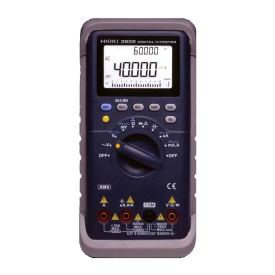
Page 13: 各部の名称と機能
各部の名称と機能 1.3 各部の名称と機能 3802-50 ディジタルハイテスタの各部の名称と機能について 説明します。 正 面 表示部 (10 ページ参照) キー操作部 (11 ページ参照) ファンクション スイッチ (12 ページ参照) 端子部 (13 ページ参照)... - Page 14 各部の名称と機能 表示部 サブ表示部と単位 メイン表示部と単位 バーグラフ 通信制御されているとき点灯します。 Remote DCV 測定、DCA 測定ファンクションのとき点灯します。 ACV 測定、ACA 測定ファンクションのとき点灯します。 AUTO オートレンジのとき点灯します。 温度測定の熱電対タイプを示します。 ℃ 選択したタイプが点灯します。 ダイオードチェックファンクションのとき点灯します。 導通チェックファンクションのとき点灯します。 相対値表示機能が ON のとき点灯します。 トリガホールド機能が ON のとき点灯します。 TRIG HOLD 最大値を表示しているとき点灯します。 (ピークホールド、レコーディング機能) 最小値を表示しているとき点灯します。 (ピークホールド、レコーディング機能) 平均値を表示しているとき点灯します。 (レコーディング機能) % 換算表示が 0-20 mA のとき点灯します。 0-20 % 換算表示が...
- Page 15 各部の名称と機能 キー操作部 SHIFT キーです。 SHIFT 現在の測定値を固定します。 (ホールド機能) 長押しすると、 レコーディング機能の ON/ OFF HOLD を行います。 相対値を表示します。 (相対値表示機能) 長押しすると、 ピークホールド機能の ON/ OFF を行います。 測定レンジを変更します。 (マニュアルレンジ) RANGE 長押しすると、オートレンジになります。 メイン表示部とサブ表示部に異なる測定値の 組み合わせを表示します。 DUAL ピークホールドモード、レコーディングモード では、再スタートします。 メイン表示部の周波数、DUTY 比、パルス幅を 選択します。 長押しすると終了します。 バックライトの ON/ OFF をします。 長押しすると、電池残量を表示します。...
- Page 16 各部の名称と機能 ファンクションスイッチ 本器の電源を OFF にします。 交流電圧測定ファンクションです。 直流電圧測定ファンクションです。 1000 mV 以下の電圧測定ファンクションです。 キーで DC、AC を切り替えます。 SHIFT 抵抗測定ファンクションです。 Ω キーで導通チェック、nS 測定ファンクションに切り替 SHIFT えます。 ダイオードチェックファンクションです。 コンデンサ容量測定ファンクションです。 キーで温度測定ファンクションに切り替えます。 SHIFT 5100 μA 以下の電流測定ファンクションです。 μA キーで DC、AC を切り替えます。 SHIFT 電流測定ファンクションです。 mA.A キーで DC、AC を切り替えます。 SHIFT...
- Page 17 各部の名称と機能 端子部 電流測定時に使用する端子です。 (A ファンクション) A 端子 テストリードの赤色を接続します。 電流測定時に使用する端子です。 (μA、mA ファンクション) μA.mA 端子 テストリードの赤色を接続します。 各測定時に共通して使用する端子です。 COM 端子 テストリードの黒色を接続します。 電圧測定、抵抗測定、ダイオードチェック、コンデンサ容量 V 端子 測定、温度測定時に使用する端子です。 テストリードの赤色を接続します。 裏 面 通信ポート ネジ 電池カバー...
- Page 18 各部の名称と機能 ホルスタ ストラップ 取り付け穴 コネクタ テストリード ホルダ スタンド ホルスタの通し穴に付属のストラップを通 ストラップ して本器を携帯できます。 取り付け穴 本器を置く場所がない場合など、 腰ベルトや フックなどに掛けて使用できます。 オプションの通信ケーブルを接続します。 コネクタ ホルスタを本器から外すとコネクタも外れ ます。紛失しないように注意してください。 テストリードを固定できます。 テストリード 一方のテストリードを固定して、 本器を持ち ホルダ ながら測定することができます。 スタンドを引き出して、 本器を立てて置くこ スタンド とができます。 本器は標準付属のホルスタが装着されています。 ホルスタは柔らかい材質のため、外部からの衝撃を吸収して 本器を保護します。 電池またはヒューズは、ホルスタを外してから交換してくだ さい。また、交換後はホルスタを装着してから使用してくだ さい。 スタンドを立てたまま、上方向から強い力を加えないでくだ さい。スタンドを損傷します。...
-
Page 19: 測定方法
測定方法 感電事故を防ぐため、下記のことをお守りください。 • 測定前に必ずファンクションスイッチの位置を確認してく ださい。 • ファンクションスイッチを切り替えるときは、テストリー ドを被測定物から外し、測定端子からも抜いてください。 • 最大入力電圧は DC1000 V、AC1000 Vrms (sin) または V Hzです。 この最大入力電圧を超えると本器を破損し、 人身事故になるので測定しないでください。 • 最大入力電流は以下の通りです。 A 端子 : AC/DC 10 A まで連続、 AC/DC 20 A まで 30 秒以内 μA.mA 端子:AC/DC 510 mA この電流を超えると本器を破損し、人身事故になるので入 力しないでください。 •... -
Page 20: 測定前の点検
測定前の点検 2.1 測定前の点検 使用前には、保存や輸送による故障がないか、点検と動作確 認をしてから使用してください。故障を確認した場合は、お 買上店(代理店)か最寄りの営業所にご連絡ください。 点検 • バッテリマーク ( ) が表示され ていませんか? → 表示されている場合は、電池を 交換してください。 (69 ページ参照) • 破損、亀裂などはありませんか? • 内部回路は露出していませんか? → お買上店(代理店)か最寄りの営 業所にご連絡ください。 • 金属が露出していませんか? • 断線していませんか? → お買上店(代理店)か最寄りの 営業所にご連絡ください。 動作確認 動作確認をして異常があった場合は、途中でも点検を中止し、 本器を使用しないでください。 用意するもの • 本器 • 3851-10 テストリード •... - Page 21 測定前の点検 テストリードの赤色を本器の V 端子に、黒色を COM 端子に 接続します。 黒 赤 テストリードの赤色と黒色の先端同士を押し当てて短絡しま す。 • ブザーが鳴る • 0 Ω 付近で値が安定している → ファンクションスイッチを ACV にします。 ( 点灯) キーを押して、メイン表示部に電圧測定値、サブ表示部 DUAL に周波数測定値が表示されるようにします。 ACコンセントの差し込み口にテストリードの先端を差し込み ます。 黒 赤 メイン画面に商用電圧、サブ画面に商用 周波数が表示されます。 これは本器の動作の一部を確認するのみです。本器が製品 仕様通り動作するかの確認には、定期的な校正が必要です。 付録 索引...
-
Page 22: 電圧測定
電圧測定 2.2 電圧測定 • 各レンジの測定範囲を超える電圧、電流を入力しないでく ださい。本器を破損します。 • 本器の電源が OFF の状態で、測定端子に電圧、電流を入力 しないでください。本器を破損することがあります。 または mV ファンクションスイッチを切り替えま す。 V :1 V 以上を測定するとき mV:1 V 以下を測定するとき 測定する電圧が不明なときは、V に合わせて ください。 キーで DC または AC を選択しま SHIFT SHIFT す。 (mV) <例> ACV 選択時 (DC) (AC) マ ニ ュ ア ル レ ン ジ に し た い 場 合 は キーを押します。... - Page 23 電圧測定 <例> 被 測定 物にテ ス ト リ ー ド を 接 続 しま 交流電圧測定 す。 黒 赤 直流電圧測定 赤 黒 メイン表示部の表示値を読みます。 <例> AC 電圧測定時 周波数を見たいときは キーまたは DUAL キーを押します。 27 ページ参照 dBm、dBV 表示を見たいときは キーを DUAL 2 回押します。 V ファンクションでは SHIFT キー(長押 し)でも...
-
Page 24: 電流測定
電流測定 2.3 電流測定 • 電圧を入力しないでください。本器を破損し、人身事故に なります。電気事故を防ぐため、測定回路の電源を切って から、測定してください。 A 端子にテストリードが接続されているときに、ファンク ションスイッチが mA.A ファンクション以外になっている と、警報が鳴ります。安全のため、警報が鳴ったときはただ ちにテストリードを被測定物から外してください。 • 各レンジの測定範囲を超える電圧、電流を入力しないでく ださい。本器を破損します。 • 本器の電源が OFF の状態で、測定端子に電圧、電流を入力 しないでください。本器を破損することがあります。... - Page 25 電流測定 ファンクションスイッチを切り替えま mA.A す。 または mA.A:5100 μA 以上を測定するとき μA μA :5100 μA 以下を測定するとき 測定する電流が不明なときは、mA.A に合わ せてください。 キーで DC または AC を選択しま SHIFT SHIFT す。 <例> ACA 選択時 (DC) (AC) マ ニ ュ ア ル レ ン ジ に し た い 場 合 は キーを押します。...
-
Page 26: 抵抗測定
抵抗測定 2.4 抵抗測定 電圧を入力しないでください。本器を破損し、人身事故にな ります。電気事故を防ぐため、測定回路の電源を切ってか ら、測定してください。 2.4.1 抵抗測定(Ω) Ω ファンクションスイッチを切り替えま す。 マ ニ ュ ア ル レ ン ジ に し た い 場 合 は (AUTO 消灯) RANGE キーを押します。 (通常はオートレ RANGE ンジです) 34 ページ参照 テ ス ト リ ー ド を 測 定 端 子 に 接 続 しま す。... -
Page 27: コンダクタンス(1/Ω)測定(Ns
抵抗測定 2.4.2 コンダクタンス(1/Ω)測定(nS) コンダクタンス測定は、抵抗の逆数を表示します。表示単位 は nS(ナノ・ジーメンス)です。 例えば、抵抗値が 40 MΩ の場合、1/ 40 MΩ=25 nS となりま す。 (M は 10 、n は 10 ) 抵抗値が∞(端子開放)では、0 nS となります。抵抗値が非 常に大きい場合に使用します。 ファンクションスイッチを切り替えま す。 キーで nS を選択します。 2 回押す SHIFT SHIFT (nS 点灯) テ スト リード を 測 定 端 子 に 接 続 しま す。... -
Page 28: 導通チェック
導通チェック 2.5 導通チェック 電圧を入力しないでください。本器を破損し、人身事故にな ります。電気事故を防ぐため、測定回路の電源を切ってか ら、測定してください。 ファンクションスイッチを切り替えま す。 キーで導通( )を選択します。 SHIFT ( 点灯) SHIFT レンジを変更したい場合は キー RANGE (AUTO 消灯) RANGE を押します。 (通常はマニュアルレンジです) オートレン ジにしたい場合は RANGE キーを長押しします。 34 ページ参照 テ ス ト リ ー ド を 測 定 端 子 に 接 続 しま 黒... -
Page 29: ダイオードチェック
ダイオードチェック 2.6 ダイオードチェック 電圧を入力しないでください。本器を破損し、人身事故にな ります。電気事故を防ぐため、測定回路の電源を切ってか ら、測定してください。 ファンクションスイッチを切り替えま す。 テストリードを測定端子に接続します。 黒 赤 被測定物にテストリードを接続します。 <例> カソード アノード 順方向 メイン表示部の表示値を読みます。 赤 黒 正常なダイオードで順方向電圧(0.3 〜 0.8 V) を表示します。 表示値が 0.0500 V 未満の場合、ブザー音が鳴 ります。 表示値が 0.3 V 〜 0.8 V に下がるとダイオード 検出としてブザー単発音が鳴ります。 ただし、相対値表示モード中は表示値ではな 付録 く内部の測定値に従います。 索引... -
Page 30: コンデンサ容量測定
コンデンサ容量測定 2.7 コンデンサ容量測定 電圧を入力しないでください。本器を破損し、人身事故にな ります。電気事故を防ぐため、測定回路の電源を切ってか ら、測定してください。 ファンクションスイッチを切り替えま す。 マ ニ ュ ア ル レ ン ジ に し た い 場 合 は (AUTO 消灯) RANGE キーを押します。 RANGE (通常はオートレ ンジです) 34 ページ参照 テ ス ト リ ー ド を 測 定 端 子 に 接 続 しま す。... -
Page 31: 周波数測定
周波数測定 2.8 周波数測定 • 各レンジの測定範囲を超える電圧、電流を入力しないでく ださい。本器を破損します。 • 本器の電源が OFF の状態で、測定端子に電圧、電流を入力 しないでください。本器を破損することがあります。 • 周波数測定範囲を超える周波数信号を測定した場合、表示 がゼロになりますので注意してください。 電圧、電流測定時に キーまたは キーを押すと、画面 DUAL に周波数が表示されます。 2.2「電圧測定」 (18 ページ)参照 2.3「電流測定」 (20 ページ)参照 最小周波数設定方法: 第 4 章「パワーオンオプション」 (45 ページ)参照 サブ表示に周波数 メイン表示に周波数 DUAL キーを押すとメイン表示部のパラメータのレンジを切 RANGE り替えます。 バーグラフは電圧測定または電流測定に従います。 付録 索引... -
Page 32: Duty 比測定
比測定 2.9 DUTY 2.9 DUTY 比測定 デューティ比 (Duty factor、Duty ratio) とは、パルス幅とパル ス繰り返し周期との比をいいます。本器ではこの比を 100 分 率 (%) で表示します。 プラススロープの マイナススロープの パルス幅 パルス幅 パルス繰り返し周期 (=tw + tw プラススロープ のデューティ比 (D+):D+ = tw /T × 100 (%) − マイナススロープ のデューティ比 (D-):D- = tw /T ×... -
Page 33: パルス幅測定
パルス幅測定 2.10 2.10 パルス幅測定 ファンクションスイッチを切り替えま す。 電圧測定:18 ページ参照 電流測定:20 ページ参照 キーで DC または AC を選択しま SHIFT SHIFT す。 キーでパルス幅を選択します。 (ms 点灯) マ ニ ュ ア ル レ ン ジ に し た い 場 合 は (AUTO 消灯) キーを押します。 RANGE (通常はオートレ... -
Page 34: 温度測定
温度測定 2.11 2.11 温度測定 電圧を入力しないでください。本器を破損し、人身事故にな ります。電気事故を防ぐため、測定回路の電源を切ってか ら、測定してください。 • 温度プローブには、 白金薄膜の精密加工が施されています。 過度に高い電圧パルスや静電気がかかると、破損する可能 性があります。 • 温度プローブ先端に過度の衝撃を加えたり、リード線を無 理に曲げないでください。故障や断線の原因になります。 • 温度プローブの握り部および補償導線が指定の温度範囲を 超えないよう注意してください。 • 被測定物の表面をきれいにして、温度プローブが確実に 当たるようにしてください。 • 外気温度以上を測定するときは、最大温度読値が得られ るまで温度プローブを被測定物の表面で動かしてくださ い。 • 外気温度以下を測定するときは、最小温度読値が得られ るまで温度プローブを被測定物の表面で動かしてくださ い。 • サブ表示部には内部温度センサによる環境温度を表示し ます。... - Page 35 温度測定 2.11 TEMP ファンクションスイッチを切り替えま す。 SHIFT ℃ キーで温度表示を選択します。 SHIFT 4.6「温度表示の設定」 (53 ページ)参照 <例> K を選択時 :本器内部温度センサによる基準接点温度 補償あり :基準接点温度補償なし ℃ (0 ℃基準) 温 度プ ローブ を 測 定 端 子 に 接 続 しま す。 − + 被 測定 物に温 度 プ ロ ー ブ を 接 続 しま <例>...
- Page 36 温度測定 2.11...
-
Page 37: オートレンジ機能
オートレンジ機能 付加機能 3.1 オートレンジ機能 オートレンジ機能は、最適なレンジを自動で選択して測定し ます。入力信号の大きさがわからないときや、レンジ設定の 手間を省きたいときに使用します。 導通チェック以外のファンクションでは、電源を入れると オートレンジになります。 (画面に「AUTO」が点灯します) 現在のレンジ (この画面は 510.00 V レンジです) しきい値 レンジ アップ ダウン フルスケール 51000 51000 カウントレンジ 51000 超 4500 未満 15000 10000 カウントレンジ − 4500 未満 51.000 A 10.000 A レンジ − 4.500 A 未満 11000 9999 カウントレンジ... -
Page 38: マニュアルレンジ機能
マニュアルレンジ機能 3.2 マニュアルレンジ機能 キーを押すとマニュアルレンジになります。キーを押 RANGE すごとにレンジアップし、小数点の位置が変わります。入力 信号の大きさがあらかじめわかっているときに使用します。 オートレンジにしたいときは、 キーを長押しします。 RANGE RANGE 5 V レンジ 51 V レンジ 1000 V レンジ 510 V レンジ • 導通チェックの初期設定はマニュアルレンジです。導通 チェック以外のファンクションでは、初期設定がオート レンジになります。 • nS 測定、ダイオードチェック、温度測定、DUTY 比測定 には、オートレンジはありません。... -
Page 39: ホールド機能
ホールド機能 3.3 ホールド機能 3.3.1 トリガホールド トリガホールド機能は、 キーを押す毎に、押した瞬間の HOLD 測定値を固定します。 リフレッシュホールド機能を OFF にします。 4.7「リフレッシュホールドの設定」 (54 ページ)参照 測定時に キーを押すと、表示値を固定します。 HOLD HOLD キーを押すごとに表示値を更新して固定します。 表示更新中(TRIG 点滅) 更新後表示固定(TRIG 点灯) トリガホールドを解除するときは、HOLD キーを長押ししま す。 付録 索引... -
Page 40: リフレッシュホールド
ホールド機能 3.3.2 リフレッシュホールド リフレッシュホールド機能は、測定値が安定すると自動的に 表示値を固定します。テストリードを被測定物から離しても 表示値は固定されたままのため、測定場所から表示値が見づ らいときや両手で測定しているときに便利な機能です。 リフレッシュホールドのしきい値(表示が安定してからの変 化量)を設定します。 しきい値の設定方法: 4.7「リフレッシュホールドの設定」 (54 ページ)参照 HOLD キーを押すと、トリガ待ち状態になります。 測定対象にテストリードを接続します。表示値が安定すると 「HOLD」が点灯し、ブザー音が鳴り表示が固定されます。 ブザー音を確認後、テストリードを測定対象から離します。 表示値は固定されたまま、 「HOLD」が点滅し、再びトリガ待 ち状態になります。 HOLD キーを長押しすると、リフレッシュホールド機能を解 除します。... - Page 41 ホールド機能 表示値が限度感度値 を超えないと表示値は固定されませ ん。表示値がうまく固定されないときは、しきい値を変更 してみてください。 * 限度感度値は各ファンクションで以下のようになっていま す。 ファンクション 限度感度値 0.05 V 0.5 mV μ μ 0.5 mA 0.05 A Ω リフレッシュホールド機能は、表示値が限度感度値を超えて 設定したしきい値の範囲内で内部測定値が安定すると、表示 を固定します。 内部測定値が、固定表示値に対ししきい値の範囲を超える毎 に表示を更新して固定します。 固定 閾値 表示値 ± 固定 表示値 内部 限度 測定値 感度値 表示固定 表示更新固定 ブザー音 ブザー音 ピッ...
-
Page 42: ピークホールド
ホールド機能 3.3.3 ピークホールド 入力信号の 1 ms(単発)または 250 μs(繰り返し)の範囲ま での変化の最大値と最小値を固定します。 入力信号の最大値: HOLD 入力信号の最小値: HOLD 測定時に キーを長押しすると、ピークホールド機能にな ります。メイン表示部に入力信号の最大値が表示されます。 更新時間 表示している最大値(最小値)を超えると表示を更新し、ブ ザー音が鳴ります。 キーを押すと入力信号の最小値が表示されます。キー HOLD を押すごとに最大値と最小値が切り替わります。 最大値、最小値、更新時間をクリアして再スタートしたいと きは、DUAL キーを押します。 キーを長押しするとピークホールド機能を解除します。 • ピークホールド機能では、 レンジは固定されます。 RANGE キーを押してレンジを選択してください。レンジを変更 すると再スタートします。 • サブ表示部には、ピークホールド機能を開始してから最 大値(最小値)を更新したまでの時間を表示します。経 過時間は 99999 秒まで表示、これを超えると OL を表示 します。... -
Page 43: レコーディング機能
レコーディング機能 3.4 レコーディング機能 レコーディング機能開始からの入力信号の最大値、 最小値、 平 均値を記録します。 入力信号の現在値:MAX MIN AVG 入力信号の最大値:MAX 入力信号の最小値:MIN 入力信号の平均値:AVG 測定時に HOLD キーを長押しすると、レコーディング機能が 開始します。 経過時間 または 更新時間 キーを押す度に最大値、最小値、平均値、現在値とメ HOLD イン表示部が切り替わります。 HOLD MAX MIN AVG 最大値(最小値)を更新するとブザー音が鳴ります。 最大値、最小値、平均値、時間をクリアして再スタートした いときは、DUAL キーを押します。 キーを長押しすると、レコーディング機能を解除しま HOLD す。 • サブ表示部には、レコーディング機能を開始してからの 経過時間(現在値、平均値)または更新時間(最大値、最 小値)を表示します。経過時間は 99999 秒まで表示、こ れを超えると... -
Page 44: 相対値(Rel)表示機能
相対値( )表示機能 3.5 相対値(REL)表示機能 キーを押すと、現在の表示値を基準値として、その相対 値を表示します。 電圧(mV)測定、抵抗測定などで測定前にテストリードを短 絡して相対値表示モードにすることで、ゼロアジャスト機能 として利用できます。 (熱起電力や配線抵抗の影響をキャンセ ルします) 基準値にしたい測定値を表示します。 キーを押すと、現在の表示値を基準値として、その相対 値を表示します。 バーグラフは表示する相対値に従います。... -
Page 45: 電池残量表示機能
電池残量表示機能 3.6 電池残量表示機能 キーを長押しすると、現在の電池残量が表示されます。 3 秒後には元の表示に自動的に戻ります。 長押し 電池電圧 6.0 〜 10.0 V に対してバーグラフは 0 〜 100% を示 します。 電池交換時期(6.0 V 以下)になると通常の測定画面にバッテ リマーク( )が表示されます。電池を交換してください。 6.3「電池の交換」 (69 ページ)参照 3.7 通信機能 本器は、RS-232C インターフェースを利用したデータの送信 機能を装備しています。 パソコンと本器を接続して、 測定デー タを本器からパソコンに転送し、データの記録と保存ができ ます。 この機能を利用するには、下記の別売りオプションが必要 です。使用するパソコンに合わせてご購入ください。 • パソコン側シリアルポート(D-sub9pin)に接続する場合 3856-01 通信パッケージ(RS-232C) •... - Page 46 通信機能 3856-02 通信パッケージを使用する場合は、パソコンに付属 のドライバをインストールします。 通信ケーブルの光コネクタ側を本体ホルスタのコネクタ部に 接続します。 「RS-232C INTERFACE」の 文字を上に向ける 「RS-232C INTERFACE」の文字を下に向けると通信できません。 通信ケーブルのもう一方のコネクタをパソコンに接続しま す。 ソフトウェアを実行します。本器からパソコンに測定データ が送信されます。 コネクタを本器から外す場合はツメを押しながら引き抜き ます。 ツメ...
-
Page 47: 警告機能
警告機能 3.8 警告機能 3.8.1 A 端子誤接続警告 A 端子にテストリードが接続されているときに、ファンク ションスイッチが mA.A ファンクション以外になっている と、警報が鳴ります。安全のため、警報が鳴ったときはただ ちにテストリードを被測定物から外してください。 付録 索引... -
Page 48: 過負荷警告
警告機能 3.8.2 過負荷警告 電圧測定で入力電圧が 1010.0 V を超えると、断続的なブザー 音で警告します。ただちにテストリードを被測定物から外し てください。 各レンジでフルスケールを超えると「OL」を表示します。 オートレンジにするか最適なレンジを選択してください。 33 ページ、34 ページ参照 レンジ フルスケール 51000 51000 カウントレンジ 15000 10000 カウントレンジ 51.000 A 10.000 A レンジ 11000 9999 カウントレンジ 99999 99999 カウントレンジ... -
Page 49: パワーオンオプション
パワーオンオプション パワーオンオプションの設定画面は、以下の項目を設定するためのものです。 パワーオンオプション 機能説明 参照ページ 通信速度を設定します。 ボーレート 47 ページ (通信のための設定) パリティチェックを設定します。 パリティチェック 47 ページ (通信のための設定) データ長を設定します。 データ長 48 ページ (通信のための設定) 応答の ON/ OFF の設定をします。 応答 48 ページ (通信のための設定) データ出力の ON/ OFF の設定をしま データ出力 49 ページ す。 (通信のための設定) % 換算表示の 4-20 mA と 0-20 mA を % 換算表示... - Page 50 パワーオンオプション設定画面一覧 SHIFT+ 電源 ON HOLD HOLD パリティチェック ボーレート設定画面 データ長設定画面 設定画面 HOLD HOLD HOLD % 換算表示設定画面 データ出力設定画面 応答設定画面 HOLD HOLD HOLD 最小基準周波数 ブザー音設定画面 デシベル表示設定画面 設定画面 HOLD HOLD HOLD オートパワーセーブ リフレッシュホールド 温度表示設定画面 設定画面 設定画面 HOLD HOLD HOLD 表示バックライト リセット画面 基準インピーダンス 設定画面 設定画面 HOLD キーを押すと逆に進みます。...
-
Page 51: 通信のための設定
通信のための設定 4.1 通信のための設定 4.1.1 通信速度の設定(ボーレート) SHIFT+ キーを押しながらファンクショ SHIFT 電源 ON ンスイッチを回すと、ボーレート設定 画面になります。 キーまたは キーで通信 RANGE DUAL 速度を選択します。 キーで確定します。 キーを長押しすると、測定画面 SHIFT に入ります。 9600 Hz(初期設定) / 19200 Hz または、ファンクションスイッチを / 2400 Hz OFF にして設定を終了します。 / 4800 Hz 4.1.2 パリティチェックの設定 SHIFT+ (1 回) キーを押しながらファンクショ... -
Page 52: データ長の設定
通信のための設定 4.1.3 データ長の設定 キーを押しながらファンクショ SHIFT+ SHIFT (2 回) 電源 ON ンスイッチを回すと、パワーオンオプ ション設定画面になります。 キーを 2 回押してデータ長設定 HOLD 画面にします。 キーまたは キーでデー RANGE DUAL タ長を選択します。 キーで確定します。 8 bit(初期設定) キーを長押しすると、測定画面 SHIFT / 7 bit に入ります。 または、ファンクションスイッチを OFF にして設定を終了します。 4.1.4 応答の ON/ OFF 設定 応答を ON にすると、本体が受信した文字をすべて返信しま す。... -
Page 53: データ出力の On/ Off 設定
通信のための設定 4.1.5 データ出力の ON/ OFF 設定 データ出力を ON にすると、 本体からサンプリングごとにデー タのみを出力します。コマンドは受信しません。 キーを押しながらファンクショ SHIFT+ SHIFT (4 回) 電源 ON ンスイッチを回すと、パワーオンオプ ション設定画面になります。 キーを 4 回押してデータ出力設 HOLD 定画面にします。 キーまたは キーでデー RANGE DUAL タ出力設定を選択します。 キーで確定します。 OFF(初期設定) / ON キーを長押しすると、測定画面 SHIFT に入ります。 または、ファンクションスイッチを OFF にして設定を終了します。 付録... -
Page 54: 換算表示(4-20 Ma/ 0-20 Ma)の切替
換算表示( )の切替 4.2 % 4-20 mA/ 0-20 mA 4.2 % 換算表示 の切替 (4-20 mA/ 0-20 mA) DCmA ファンクションで測定時、DUAL キーを 3 回押すとサ ブ表示部に % 換算表示が表示されます。 ここでは、その % 換算表示の表示方式を設定します。 4-20 mA 4 mA - 20 mA を 0%-100% に換算して表示します。 0-20 mA 0 mA - 20 mA を 0%-100% に換算して表示します。 キーを押しながらファンクショ... -
Page 55: 最小周波数の設定
最小周波数の設定 4.3 最小周波数の設定 周波数測定の最小周波数を設定します。最小周波数を設定す ることで低周波数測定でのサンプリング時間 (ゲート時間) が 決まります。 → <例> 最小周波数 0.5 Hz サンプリング時間 2s キーを押しながらファンクショ SHIFT+ SHIFT (6 回) 電源 ON ンスイッチを回すと、パワーオンオプ ション設定画面になります。 キーを 6 回押して最小周波数設 HOLD 定画面にします。 キーまたは キーで最小 RANGE DUAL 周波数を選択します。 キーで確定します。 0.5 Hz(初期設定) / 1 Hz キーを長押しすると、測定画面 SHIFT / 2 Hz に入ります。... -
Page 56: デシベル(Dbm/ Dbv)の表示切替
デシベル( )の表示切替 dBm/ dBV 4.5 デシベル の表示切替 (dBm/ dBV) 電圧測定時、 キーを 2 回押すとメイン表示部にデシベル DUAL 換算値が表示されます。ここでは、その表示方式を設定しま す。 電圧測定で基準抵抗による電力 1 mW に対する電力比をデ シベルに換算して表示します。 電圧測定で基準電圧 1 V に対する電圧比をデシベルに換算 して表示します。 キーを押しながらファンクショ SHIFT+ SHIFT (8 回) 電源 ON ンスイッチを回すと、パワーオンオプ ション設定画面になります。 キーを 8 回押してデシベル表示 HOLD 設定画面にします。 キーまたは... -
Page 57: 温度表示の設定
温度表示の設定 4.6 温度表示の設定 サブ表示部に環境温度を表示するかしないか設定します。 (本器に内蔵されている温度センサによる測定) キーを押しながらファンクショ SHIFT+ SHIFT (6 回) 電源 ON ンスイッチを回すと、パワーオンオプ ション設定画面になります。 キーを 6 回押して温度表示設定 画面にします。 キーまたは キーで温度 RANGE DUAL 表示を選択します。 キーで確定します。 OFF(初期設定) キーを長押しすると、測定画面 SHIFT / ON に入ります。 または、ファンクションスイッチを OFF にして設定を終了します。 付録 索引... -
Page 58: リフレッシュホールドの設定
リフレッシュホールドの設定 4.7 リフレッシュホールドの設定 リフレッシュホールド機能のしきい値を設定します。しきい 値は表示値が安定してからの変化量で、設定した変化量を基 準に表示を固定します。OFF に設定するとリフレッシュホー ルド機能は無効となり、トリガホールド機能が有効になりま す。 キーを押しながらファンクショ SHIFT+ SHIFT (5 回) 電源 ON ンスイッチを回すと、パワーオンオプ ション設定画面になります。 キーを 5 回押してリフレッシュ ホールド設定画面にします。 リフレッシュホールド機能を選択し ます。 キー:数値を上げる RANGE キー:数値を下げる DUAL OFF(初期設定)/ キーで確定します。 100 カウント〜 1000 カウント キーを長押しすると、測定画面 SHIFT に入ります。 または、ファンクションスイッチを OFF にして設定を終了します。... -
Page 59: オートパワーセーブの設定
オートパワーセーブの設定 4.8 オートパワーセーブの設定 オートパワーセーブ機能が ON になるまでの時間を設定しま す。ロータリスイッチまたはキーの最終操作から設定時間が 経過するとオートパワーセーブ機能が ON になります。オー トパワーセーブ機能により表示画面が消灯し、本体内部の電 源消費を抑えます。 • オートパワーセーブ機能から復帰するには、ロータリス イッチを一度 OFF にして電源を入れ直すか、何かキーを 押します。ただし、電源 ON の状態となります。 • ピークホールド機能、レコーディング機能ではオートパ ワーセーブ機能は自動的に無効となります。 キーを押しながらファンクションスイッチを回して電 • 源を入れると、オートパワーセーブ機能は無効となりま す。 (初回のみ) キーを押しながらファンクショ SHIFT+ SHIFT (4 回) 電源 ON ンスイッチを回すと、パワーオンオプ ション設定画面になります。 キーを 4 回押してオートパワー セーブ設定画面にします。... -
Page 60: 表示バックライトの設定
表示バックライトの設定 4.9 表示バックライトの設定 表示バックライトが消灯するまでの時間を設定します。表示 バックライトは、 キーを押すと点灯します。設定時間内に消 灯させたいときは、再度 キーを押します。 キーを押しながらファンクショ SHIFT+ SHIFT (3 回) 電源 ON ンスイッチを回すと、パワーオンオプ ション設定画面になります。 キーを 3 回押して表示バックラ イト設定画面にします。 バックライトの点灯時間を設定しま す。 キー:数値を上げる RANGE キー:数値を下げる DUAL 30 s(初期設定) キー:上位の桁を選択 SHIFT / 1 〜 99 s / OFF キーで確定します。 キーを長押しすると、測定画面 SHIFT に入ります。... -
Page 61: 基準インピーダンスの設定
基準インピーダンスの設定 4.10 4.10 基準インピーダンスの設定 デシベル(dBm)換算表示の基準インピーダンスを設定しま す。 キーを押しながらファンクショ SHIFT+ SHIFT (2 回) 電源 ON ンスイッチを回すと、パワーオンオプ ション設定画面になります。 キーを 2 回押して基準インピー ダンス設定画面にします。 基準インピーダンスを設定します。 キー:数値を上げる RANGE キー:数値を下げる DUAL キー:上位の桁を選択 SHIFT 1 〜 9999 Ω (初期設定:600 Ω) キーで確定します。 キーを長押しすると、測定画面 SHIFT に入ります。 または、ファンクションスイッチを OFF にして設定を終了します。 付録 索引... -
Page 62: リセット
リセット 4.11 4.11 リセット パワーオンオプションの設定内容を初期値にリセットしま す。 キーを押しながらファンクショ SHIFT+ SHIFT (1 回) 電源 ON ンスイッチを回すと、パワーオンオプ ション設定画面になります。 キーを 1 回押してリセット画面 にします。 キーを長押ししてリセットを実行 します。 キーを長押しすると、測定画面 SHIFT に入ります。 Default(初期設定) または、ファンクションスイッチを OFF にして設定を終了します。 パワーオンオプション 初期値 9600 bps ボーレート パリティチェック なし 8 bit データ長 応答 データ出力 4-20 mA % 換算表示... -
Page 63: 一般仕様
一般仕様 仕様 5.1 一般仕様 交流測定方式 真の実効値測定方式 測定機能 • 直流電圧 • 交流電圧 • 直流電流 • 交流電流 • 抵抗 • 導通 • ダイオード • 静電容量 • 周波数 • DUTY 比 • パルス幅 • 温度 付加機能 • オートレンジ機能 • マニュアルレンジ機能 • 通信機能(RS-232C、USB) • リフレッシュホールド機能 •... - Page 64 一般仕様 表示 • データ表示 メイン表示部 4 1/2 桁、サブ表示部 4 1/2 桁 最大カウント [51000] 最大カウント [15000] 1000 V レンジ / 1000 mV レンジ 最大カウント [99999] Hz ファンクション 最大カウント [9999] C ファンクション 極性表示 [-] マーク自動点灯 オーバレンジ表示 [OL] または [-OL] • バーグラフ スケール表示、21 ドットバー表示、±極性表示 レンジカウント表示...
- Page 65 一般仕様 付属品 3851-10 テストリード ストラップ ホルスタ(本体装着) 取扱説明書 積層形アルカリ乾電池(6LR61)× 1 (本体内蔵モニタ用) μA.mA端子用440 mAヒューズ (AC/DC 1000 V遮断容量30 交換部品 kA、SIBA 社製速断型ヒューズ φ10 × 38 mm) A 端子用 11 A ヒューズ(AC/DC 1000 V 遮断容量 30 kA、 SIBA 社製速断型ヒューズ φ10 × 38 mm) オプション 3853 携帯用ケース 3856-01 通信パッケージ(RS-232C)...
- Page 66 一般仕様 測定確度 確度表による サンプルレート 確度表による 確度保証電源電圧 10.2 V から マーク点灯まで 範囲 確度保証温湿度範囲 23 ℃± 5 ℃、80%rh 以下(結露なし) 確度保証期間 1 年間 温度特性 測定確度× 0.15/ ℃ ノイズ除去 NMRR DCV:60 dB 以上(50 Hz/ 60 Hz) ACV:60 dB 以上(DC) ノイズ除去 CMRR DCV:90 dB 以上(DC/ 50 Hz/ 60 Hz、1 kΩ unbalance) ACV:60 dB 以上(DC/ 50 Hz/ 60 Hz、1 kΩ...
- Page 67 確度 5.2 確度 (23 ℃± 5 ℃ 80%rh 以下において保証) DC mV/ V(直流電圧) 入力インピー レンジ 確度 過負荷保護 ダンス 51.000 mV ± 0.05%rdg. ± 50 dgt. DC1000 V/ AC1000 Vrms (sin)または 10 VHz、 510.00 mV 1 GΩ 以上 過渡過電圧 8000 V 1000.0 mV 過負荷時電流...
- Page 68 確度 DC μA/ mA/ A(直流電流) 入力インピーダンス レンジ 確度 負荷電圧 過負荷保護 (シャント抵抗) 510.00 μA 0.06 V ± 0.1%rdg. 100 Ω 保護ヒューズ 440 mA 5100.0 μA ± 25 dgt. 0.6 V AC/DC 1000 V 51.000 mA ± 0.2%rdg. 0.09 V 遮断容量 30 kA 1 Ω...
- Page 69 確度 Ω(抵抗)/ 導通 レンジ 確度 測定電流 開放端子電圧 過負荷保護 510.00 Ω ± 0.08%rdg. ± 10 dgt. 約 1.00 mA DC1000 V/ 5.1000 kΩ ± 0.08%rdg. ± 5 dgt. 約 0.38 mA AC1000 Vrms 約 38 μA 51.000 kΩ (sin)または ± 0.08%rdg. ± 5 dgt. 約...
- Page 70 確度 DUTY 比 / パルス幅 ファンクション レンジ 確度 過負荷保護 DUTY 99.99% DC1000 V/ AC1000 ± 0.3%/ kHz ± 0.3% Vrms(sin) 510.00 ms または 10 PULSE ± 0.2%rdg. ± 3 dgt. 1999.9 ms 1 分間印加 確度は DC5.1000 V レンジの振幅 5 V、パルス幅 10 μs 以上の方形波入力に対し規定 AC 結合は...
-
Page 71: 保守・サービス
困ったときは 保守・サービス 6.1 困ったときは • 故障と思われるときは、 「修理に出される前に」 (68 ページ) を確認してから、お買上店(代理店)か最寄りの営業所に ご連絡ください。 • 本器の調整や修理は、危険を良く知った技能者の責任で 行ってください。 • 本器を輸送するときは、 輸送中に破損しないように梱包し、 故障内容も書き添えてください。輸送中の破損については 保証しかねます。 • 改造は絶対にしないでください。また修理技術者以外の人 は、分解や修理をしないでください。火災や感電事故、け がの原因になります。 • 本器の保護機能が破損している場合は、使用できないよう に廃棄するか、知らないで動作させることのないように、 表示しておいてください。 本器の確度維持あるいは確認には、定期的な校正が必要です。 修理・校正業務のご用命は、 「日置エンジニアリングサービス (株) 」 までお願いいたします。 (TEL 0268-28-0823、 FAX 0268- 28-0824) 長期間(1 年以上)保管した場合、本器が規定している仕様が 満足できなくなります。使用するときには本器の校正をご依... - Page 72 困ったときは 修理に出される前に 動作がおかしいとき、以下の項目をチェックしてください。 症状 チェック項目 電池が消耗していませんか? → 電池を交換してください。 (69 ページ参照) 画面に表示がでない 電池スナップのケーブルが断線していませんか? → お買上店(代理店)か最寄りの営業所にご連絡くださ い。 電池が消耗していませんか? → 電池を交換してください。 (69 ページ参照) 画面の表示がしばら オートパワーセーブ機能が動作していませんか? くすると消える → オートパワーセーブの設定を確認してください。 (55 ページ参照) ヒューズが断線していませんか? → ヒューズを交換してください。 (71 ページ参照) 電流測定できない テストリードが断線していませんか? →本器の導通チェックでテストリードの導通チェックを してください。断線の場合、テストリードを交換して ください。 (24 ページ参照) ヒューズ交換で本器を開けた際、ファンクションスイッ ファンクションス...
-
Page 73: クリーニング
クリーニング 6.2 クリーニング 本器の汚れをとるときは、柔らかい布に水か中性洗剤を少量 含ませて、軽くふいてください。ベンジン、アルコール、ア セトン、エーテル、ケトン、シンナー、ガソリン系を含む洗 剤は絶対に使用しないでください。変形、変色することがあ ります。 表示部は乾いた柔らかい布で軽く拭いてください。 6.3 電池の交換 • 感電事故を避けるため、 ファンクションスイッチを OFF に し、テストリードを外してから電池を交換してください。 交換後は、必ずカバーをしてから、ネジ留め後に使用して ください。 • 極性+−に注意し、逆挿入しないでください。性能劣化や 液漏れの原因になります。また必ず指定の電池と交換して ください。 • 使用済の電池をショート、分解または火中への投入はしな いでください。破裂する恐れがあり危険です。 • 使用済の電池は地域で定められた規則に従って処分してく ださい。 バッテリマーク( 点灯時は、電池が消耗していますの ) で、早めに交換してください。 付録 索引... - Page 74 電池の交換 テストリードを本器から外し、ファンクションスイッチを OFF にします。 本器からホルスタを外します。 マイナスドライバなどで電池カバーのネジを OPEN の位置ま で回し、電池カバーを横にスライドさせ、次に上に持ち上げ て本器から外します。 ① ② 電池を電池スナップから外し、新しい電池と交換します。 電池の形名:6F22(マンガン)または 6LR61(アルカリ) 電池カバーをネジ留めし、ホルスタを装着します。 ケースを留めるときは電池スナップのケーブルを挟まないよ う注意してください。 電池カバーがうまくセットできない場合は、ネジが OPEN の 位置になっているか確認してください。...
-
Page 75: ヒューズの交換
ヒューズの交換 6.4 ヒューズの交換 • 感電事故を避けるため、 ファンクションスイッチを OFF に し、テストリードを外してからヒューズを交換してくださ い。交換後は、必ずカバーをしてから、ネジ留め後に使用 してください。 • ヒューズは、指定された形状と特性、定格電流、電圧のも のを使用してください。指定以外のヒューズを用いたり ヒューズホルダを短絡して使用すると、人身事故になるの で注意してください。 指定ヒューズ: μA.mA 端子用 5019906-440 mA/ 1000 VACDC/ 30 kA φ (SIBA 社製速断型ヒューズ 10 × 38 mm) A 端子用 5019906-11A/ 1000 VACDC/ 30 kA φ (SIBA 社製速断型ヒューズ... - Page 76 ヒューズの交換 ネジ(3 箇所)を外し、下ケースを外します。 上ケースからプリント基板を引き出します。 断線したヒューズを外し、新しい指定のヒューズを取り付け ます。 ヒューズの形名: μA.mA 端子用 5019906-440 mA/ 1000 VACDC/ 30 kA φ (SIBA 社製速断型ヒューズ 10 × 38 mm) A 端子用 5019906-11A/ 1000 VACDC/ 30 kA φ (SIBA 社製速断型ヒューズ 10 × 38 mm) A 端子用 μA.mA 端子用 上ケースのファンクションスイッチとプリント基板のスイッ...
-
Page 77: 本体ソフトのバージョンの確認方法
本体ソフトのバージョンの確認方法 6.5 本体ソフトのバージョンの確認方法 以下の方法で本体ソフトのバージョン No. を確認することが できます。 キーを押しながら電源を入れます。 ブザー音と同時に キーを離します。 メイン画面にバージョン No. が表示されます。 1.09 この画面ではバージョン No.「 」です。 任意のキーを押すと表示部が全点灯し、測定画面になります。 付録 索引... - Page 78 本体ソフトのバージョンの確認方法...
- Page 79 保 証 書 形名 製造番号 保証期間 3802-50 購入日 年 月より 3 年間 本製品は、弊社の厳密なる検査を経て合格した製品をお届けした物です。 万一ご使用中に故障が発生した場合は、お買い求め先にご連絡ください。本書の記載 内容で無償修理をさせていただきます。 また、製品の使用による損失については、購 入金額までの支払いとさせていただきます。 なお、 保証期間は購入日より 3 年間です。 購入日が不明の場合は、製品の製造月から 3 年を目安とします。 ご連絡の際は、本書 を提示してください。 また、確度については、明示された確度保証期間によります。 お客様 ご住所 : 〒 ご芳名 : *お客様へのお願い • 保証書の再発行はいたしませんので、大切に保管してください。 • 「 形名、製造番号、購入日」およびお客様「ご住所、ご芳名」は恐れ入りますが、お 客様にて記入していただきますようお願いいたします。 1. 取扱説明書 • 本体注意ラベル (刻印を含む) 等の注意事項にしたがった正常な使用...
- Page 81 3802-50 DIGITAL HiTESTER Instruction Manual...
- Page 83 Contents Contents Introduction .................1 Verifying Package Contents ..........1 Safety Information ..............2 Operating Precautions ............5 1 Overview Product Overview .............7 Features ..............8 Names and Functions of Parts .........9 2 Measurement Pre-Operation Inspection ........17 Voltage Measurement ..........19 Current Measurement ..........21 Resistance Measurement ........23 Ω...
- Page 84 Contents Communications Function ........43 Warning Functions ..........45 3.8.1 Terminal A Misconnection Warning ......45 3.8.2 Overload Warning ............46 4 Power On Options Communications Settings ........49 4.1.1 Communications Speed Setting (Baud Rate) ..49 4.1.2 Parity Check Setting ..........49 4.1.3 Data Length Setting ..........50 4.1.4 Response ON/OFF Setting ........50 4.1.5 Data Output ON/OFF Setting ........51 Toggling the Percentage Display...
-
Page 85: Introduction
Introduction Thank you for purchasing the HIOKI “Model 3802-50 DIGITAL HiTESTER.” To obtain maximum performance from the instrument, please read this manual first, and keep it handy for future reference. Verifying Package Contents • When you receive the instrument, inspect it carefully to ensure that no damage occurred during shipping. -
Page 86: Safety Information
Safety Information This instrument is designed to comply with IEC 61010 Safety Standards, and has been thoroughly tested for safety prior to shipment. However, mis- handling during use could result in injury or death, as well as damage to the instrument. Be certain that you understand the instructions and precautions in the manual before use. - Page 87 The following symbols in this manual indicate the relative importance of cautions and warnings. Indicates that incorrect operation presents an extreme hazard that could result in seri- ous injury or death to the user. Indicates that incorrect operation presents a significant hazard that could result in serious injury or death to the user.
- Page 88 Measurement categories (Overvoltage categories) This instrument complies with CAT III (1000 V) and CAT IV (600 V) safety requirements. To ensure safe operation of measurement instruments IEC 61010 establishes safety standards for various elec- trical environments, categorized as CAT I to CAT IV, and called measurement categories.
-
Page 89: Operating Precautions
Using the instrument in such conditions could cause an electric shock, so contact your dealer or Hioki rep- resentative for replacements. (Model 3851-10 TEST LEAD) - Page 90 Measurement Precautions Observe the following precautions to avoid electric shock. • Always verify the appropriate setting of the func- tion selector before connecting the test leads. • Disconnect the test leads from the measurement object and terminals before switching the function selector.
-
Page 91: Overview 7
1.1 Product Overview Overview 1.1 Product Overview The 3802-50 is a multifunction, high-performance digital multimeter that can be used for voltage (DC/AC), current (DC/AC), resistance, continuity, diodes, electrostatic capacity, frequency, duty ratio, pulse width, and tempera- ture measurement. Furthermore, this instrument can be controlled by computer and transfer measurement data to the computer when the optional 3856-01/02 is used. -
Page 92: Features
1.2 Features 1.2 Features High-performance Handheld DMM The 3802-50 can display a maximum count of 51,000. It can even measure distorted waveforms with high-preci- sion using true RMS measurement. The basic accuracy for DC voltage measurement is 0.03% rdg. 10 dgt. -
Page 93: Names And Functions Of Parts
1.3 Names and Functions of Parts 1.3 Names and Functions of Parts The name and function of each part of the 3802-50 is described below. Front Panel Display (10 page) Operation Keys (11 page) Function Selector (12 page) Terminals (13 page) - Page 94 1.3 Names and Functions of Parts Sub display and units Display Main display and units Bar graph Lights when under remote control. Remote Lights when the DCV measurement or DCA measurement func- tion is being used. Lights when the ACV measurement or ACA measurement func- tion is being used.
- Page 95 1.3 Names and Functions of Parts Operation Keys SHIFT key SHIFT Locks the current measured value. (Hold function) HOLD Holding this key down toggles the recording function ON/OFF. Displays the relative value. (Relative value display function) Holding this key down toggles the peak hold function ON/OFF.
- Page 96 1.3 Names and Functions of Parts Function Selector Pressing this key turns the instrument off. AC voltage measurement function Voltage measurement function Voltage measurement function up to 1000 mV. Use the key to select DC or AC. SHIFT Resistance measurement function Ω...
- Page 97 1.3 Names and Functions of Parts Terminals Terminal used for current measurement. (A function) A Terminal Connect the read test lead. Terminal used for current measurement. (μA and mA μ function) A.mA Terminal Connect the read test lead. Common terminal used for all measurements. COM Terminal Connect the black test lead.
- Page 98 Holder Stand Pass the strap provided through the hole in the holster to Strap secure the 3802-50 for portable use. The strap can be Attachment used to suspend the instrument from a belt or hook when Hole there is no place to set it down.
-
Page 99: Measurement 15
Measurement Observe the following precautions to avoid electric shock. • Always verify the appropriate setting of the func- tion selector before connecting the test leads. • Disconnect the test leads from the measurement object before switching the function selector. • The maximum input voltage is 1000 VDC, 1000 Vrms (sin) or 10 VHz. - Page 100 The terminals do not have sufficient spatial isola- tion. To avoid electrocution, do not touch the termi- nals. For safety reasons, when taking measurements, only use the test lead provided with the instrument. In order to protect the tips of the test leads, the test leads are capped when the unit is shipped from the factory.
-
Page 101: Pre-Operation Inspection
Before using the instrument the first time, verify that it operates normally to ensure that the no damage occurred during storage or shipping. If you find any damage, con- tact your dealer or Hioki representative. Inspection • Is the battery indicator ( ) lit? →If it is lit, replace the battery. - Page 102 2.1 Pre-Operation Inspection Connect the red test lead to the V terminal, and the black test lead to the COM terminal. Black Short the tips of the red and black test leads by touching them together. • Buzzer sounds. • Value stabilizes around 0 Ω. →...
-
Page 103: Voltage Measurement
2.2 Voltage Measurement 2.2 Voltage Measurement • Note that the instrument may be damaged if voltage or current the measurement range. • When the power is turned off, do not apply voltage or current to the measurement terminal. Doing so may damage the instrument. - Page 104 2.2 Voltage Measurement <Example> Connect the test leads to the object ACV Measurement being tested. Black DCV Measurement Black <Example> Read the value displayed in the When measuring AC voltage main display. To display the frequency, press the or the key.
-
Page 105: Current Measurement
2.3 Current Measurement 2.3 Current Measurement Never apply voltage to the test leads. Doing so may damage the instrument and result in personal injury. To avoid electrical accidents, remove power from the circuit before measuring. When a test lead is connected to terminal A, an alarm sounds if the function switch is set to a func- tion other than mA or A. - Page 106 2.3 Current Measurement Set the function switch. mA.A mA.A: For measuring voltages above 5100 μA μA : For measuring voltages below 5100 μA μA If you are not sure of the voltage to be mea- sured, set the function switch to "mA.A". Use the key to select either DC SHIFT...
-
Page 107: Resistance Measurement
2.4 Resistance Measurement 2.4 Resistance Measurement Never apply voltage to the test leads. Doing so may damage the instrument and result in personal injury. To avoid electrical accidents, remove power from the circuit before measuring. Ω 2.4.1 Resistance Measurement ( Ω... -
Page 108: Conductance
2.4 Resistance Measurement Ω 2.4.2 Conductance (1/ )Measurement (nS) The conductance measurement displays the reciprocal of the resistance. The display unit is "nS" (nanosiemens). For example, if the resistance is 40 MΩ, the conductance measurement will be 1/40 MΩ = 25 nS. (M is 10 , n is 10 If the resistance is infinity, 0 nS is displayed. -
Page 109: Continuity Check
2.5 Continuity Check 2.5 Continuity Check Never apply voltage to the test leads. Doing so may damage the instrument and result in personal injury. To avoid electrical accidents, remove power from the circuit before measuring. Set the function switch. Select with the key. -
Page 110: Diode Check
2.6 Diode Check 2.6 Diode Check Never apply voltage to the test leads. Doing so may damage the instrument and result in personal injury. To avoid electrical accidents, remove power from the circuit before measuring. Set the function switch. Connect the test leads to the test ter- minals. -
Page 111: Capacitance Measurement
2.7 Capacitance Measurement 2.7 Capacitance Measurement Never apply voltage to the test leads. Doing so may damage the instrument and result in personal injury. To avoid electrical accidents, remove power from the circuit before measuring. Set the function switch. If you want to change the range, press the key. -
Page 112: Frequency Measurement
2.8 Frequency Measurement 2.8 Frequency Measurement • Note that the instrument may be damaged if voltage or current the measurement range. • When the power is turned off, do not apply voltage or current to the measurement terminal. Doing so may damage the instrument. -
Page 113: Duty Ratio Measurement
2.9 DUTY Ratio Measurement 2.9 DUTY Ratio Measurement The duty ratio is the ratio between the pulse width and the pulse cycle. This instrument displays this ratio in terms of 100 (%). Plus slope pulse Minus slope pulse width width Pulse cycle (=tw + tw Plus slope... -
Page 114: Pulse Width Measurement
2.10 Pulse Width Measurement 2.10 Pulse Width Measurement Set the function switch. See Section 2.2 Voltage Measurement (page 19) See Section 2.3 Current Measurement (page Use the key to select either DC SHIFT or AC. SHIFT Use the key to select the Pulse width. -
Page 115: Temperature Measurement
2.11 Temperature Measurement 2.11 Temperature Measurement Never apply voltage to the test leads. Doing so may damage the instrument and result in personal injury. To avoid electrical accidents, remove power from the circuit before measuring. • The sensor used in the temperature probe is a thin, precision platinum film. - Page 116 2.11 Temperature Measurement TEMP Set the function switch. Use the key to select the tem- SHIFT perature display. ° SHIFT : Uses reference contact temperature compensation according to the instru- <Example> K is selected ment's internal temperature sensor : No reference contact temperature °...
-
Page 117: Additional Functions
3.1 Auto Range Function Additional Functions 3.1 Auto Range Function The auto range function automatically selects the optimal range for measurement. Use this function when you do not know the strength of the input signal or if you wish to avoid having to set the range manually. -
Page 118: Manual Range Function
3.2 Manual Range Function 3.2 Manual Range Function Press the key to set the manual range function. RANGE Each time the key is pressed the range increases, and the position of the decimal point changes. Use this func- tion when you know the strength of the input signal. To change to auto range, hold down the key. -
Page 119: Hold Functions
3.3 Hold Functions 3.3 Hold Functions 3.3.1 Trigger Hold Function The trigger hold function locks the value that was being measured at the moment that the key was pressed. HOLD Turn the refresh hold function off. See Section 4.7 Refresh Hold Setting (page 58) Press the key during measurement to lock the HOLD... -
Page 120: Refresh Hold Function
3.3 Hold Functions 3.3.2 Refresh Hold Function The refresh hold function locks the display value auto- matically once the measurement value stabilizes. As the display value remains locked even if you remove the test leads from the test subject, this function is useful when you are measuring in locations where it is difficult to see the display value or when you are using both hands to take measurements. - Page 121 3.3 Hold Functions If the display value does not exceed the threshold value that was set, the display value is not locked in. If you have trouble getting the display value to lock, try changing the threshold value. * The threshold value of each function is shown below. Function Threshold value 0.05 V...
-
Page 122: Peak Hold Function
3.3 Hold Functions 3.3.3 Peak Hold Function This function locks in the maximum and minimum change in the measured value of an input signal over a period of 1ms (one-shot) or 250 μþs (repetitive). Input signal maximum value : HOLD Input signal minimum value : HOLD To turn on the PEAK HOLD function, hold down the... -
Page 123: Recording Function
3.4 Recording Function • The range is locked in the peak hold function. Press key to select the range. Changing the RANGE range restarts the function. • The sub display shows the time from the start of the peak hold function until the maximum (minimum) value was updated. - Page 124 3.4 Recording Function Press the key again to toggle between the maxi- HOLD mum value, minimum value, average value, current value and the main display. HOLD MAX MIN AVG When the maximum value (or minimum value) is updated, the buzzer sounds. To clear the maximum value, minimum value average value and time and restart, press the key.
-
Page 125: Relative (Rel) Display Function
3.5 Relative (REL) Display Function 3.5 Relative (REL) Display Function Pressing the key causes future values to be dis- played relative to the currently displayed value, which becomes the reference value. To reproduce a zero adjust function while measuring volt- age (mV), resistance, etc., short the test leads to set the relative value display mode. -
Page 126: Battery Indicator Function
3.6 Battery Indicator Function 3.6 Battery Indicator Function Holding down the key causes the current battery level to be displayed. The original display returns automati- cally after three seconds. Hold down The bar graph displays a reading from 0 to 100% for the battery voltage over a range from 6.0 to 10.0 V. -
Page 127: Communications Function
Model 3856-01 or Model 3856-02 Instruction Manual Install the software in the personal computer. Model 3856-01 or Model 3856-02 Instruction Manual Set up the personal computer and the 3802-50 for communications. See Section 4.1 Communications Settings (page 49) When the software of the communications package is used, set up the instrument as follows. - Page 128 3.7 Communications Function Connect the optical connector of the communications cable to the connector on the holster for the 3802-50. Make sure "RS-232C INTERFACE" is facing upwards Communication is not possible if "RS-232C INTERFACE" is facing downwards. Connect the other end of the communications cable to the personal computer.
-
Page 129: Warning Functions
3.8 Warning Functions 3.8 Warning Functions 3.8.1 Terminal A Misconnection Warning When a test lead is connected to terminal A, an alarm sounds if the function switch is set to a func- tion other than mA or A. For safety, if the alarm sounds, immediately remove the test lead from the object being tested. -
Page 130: Overload Warning
3.8 Warning Functions 3.8.2 Overload Warning During voltage measurement, if the input voltage exceeds 1010.0 V, the 3802-50 sounds an intermittent beep as a warning. Remove the test leads from the test subject immediately. If full scale is exceeded in any of the ranges, "OL" is displayed. -
Page 131: Power On Options
Power On Options The Power On Option Setting screen is used to set the following items. Power On Option Description Ref Page Sets the communications speed. Baud Rate (49 page) (communications setting) Sets parity checking. Parity Check (49 page) (communications setting) Sets the data length. - Page 132 Power On Option Setting Screen List +Power On SHIFT HOLD HOLD Baud Rate Data Length Parity Check setting screen setting screen setting screen HOLD HOLD HOLD Percentage Display Data Output Response setting setting screen setting screen screen HOLD HOLD HOLD Minimum Frequency Decibel Display Buzzer Sound...
-
Page 133: Communications Settings
4.1 Communications Settings 4.1 Communications Settings 4.1.1 Communications Speed Setting (Baud Rate) SHIFT + 1. In order to display the Baud Rate Power On setting screen, hold down the key while turning the func- SHIFT tion switch. 2. Press the key or the RANGE DUAL... -
Page 134: Data Length Setting
4.1 Communications Settings 4.1.3 Data Length Setting 1. In order to display the Power On SHIFT + (twice) Power On Option setting screen, hold down key while turning the SHIFT function switch. 2. Press the key twice to dis- HOLD play the Data Length setting screen. -
Page 135: Data Output On/Off Setting
4.1 Communications Settings 4.1.5 Data Output ON/OFF Setting If data output is on, this instrument only outputs data after each sample. It does not receive commands. 1. In order to display the Power On SHIFT + (4 times) Power On Option setting screen, hold down key while turning the SHIFT... -
Page 136: Toggling The Percentage Display (4 - 20Ma/0 - 20Ma)
4.2 Toggling the Percentage Display (4 - 20mA/0 - 20mA) 4.2 Toggling the Percentage Display (4 - 20mA/0 - 20mA) When measuring with the DCmA function, press the key three times to display the percentage display in DUAL the sub display. This procedure sets the percentage display method. -
Page 137: Minimum Frequency Setting
4.3 Minimum Frequency Setting 4.3 Minimum Frequency Setting Sets the minimum frequency for frequency measurement. The setting of the minimum frequency determines the sampling time (gate time) used in low frequency mea- surement. <Example> → Minimum frequency 0.5 Hz Sampling time 2 s 1. -
Page 138: Buzzer Sound Setting
4.4 Buzzer Sound setting 4.4 Buzzer Sound setting The buzzer sound can be set as preferred. 1. In order to display the Power On SHIFT + (7 times) Power On Option setting screen, hold down key while turning the SHIFT function switch. -
Page 139: Toggling The Decibel Display (Dbm/ Dbv)
4.5 Toggling the Decibel Display (dBm/ dBV) 4.5 Toggling the Decibel Display (dBm/ dBV) While measuring voltage, pressing the key twice DUAL displays the measured value converted into decibels in the sub display. The procedure for setting this display method is described below. During voltage measurement, converts into decibels the ratio of power versus power of 1 mW for the refer- ence resistance. - Page 140 4.5 Toggling the Decibel Display (dBm/ dBV) <Display example> 600 Ω (Measured value [V]) X 1000 [dBm] dBm = 10log Reference resistance [Ω] Select through power on option dBV = 20log (Measured value[V]) [dBV] Setting Method of reference resistance: See Section 4.10 Reference Impedance Setting (page 61)
-
Page 141: Temperature Display Setting
4.6 Temperature Display Setting 4.6 Temperature Display Setting Set whether to display the ambient temperature or not in the sub display. (The ambient temperature is measured by a temperature sensor in the instrument.) 1. In order to display the Power On SHIFT + (6 times) Power On... -
Page 142: Refresh Hold Setting
4.7 Refresh Hold Setting 4.7 Refresh Hold Setting This procedure sets the threshold value for the refresh hold function. The threshold value locks the display to showing the amount of change after the display value has stabilized, using the set amount of change as a criteria. Setting this to off disables the refresh hold function and enables the trigger hold function. -
Page 143: Auto Power Save Function
RANGE DUAL switch to a position other than pulse output and then back to its original position. The 3802-50 reverts to the power ON state. • The auto power save function is automatically dis- abled when either the peak hold function or the recording function is used. -
Page 144: Display Backlight Setting
4.9 Display Backlight Setting 4.9 Display Backlight Setting This procedure sets the time until the display backlight turns off. To turn on the display backlight, press the key. To turn off the display backlight before the time elapses, press the key again. -
Page 145: Reference Impedance Setting
4.10 Reference Impedance Setting 4.10 Reference Impedance Setting This procedure sets the reference impedance for the decibel (dBm) conversion screen. 1. In order to display the Power On SHIFT + (twice) Power On Option setting screen, hold down key while turning the SHIFT function switch. -
Page 146: Reset
4.11 Reset 4.11 Reset This procedure resets the power on option settings to their initial values. 1. In order to display the Power On SHIFT + (once) Power On Option setting screen, hold down key while turning the SHIFT function switch. 2. -
Page 147: Specifications
5.1 General Specifications Specifications 5.1 General Specifications AC measurement True RMS measurement method Measurement • DC voltage measurement functions • AC voltage measurement • DC current measurement • AC current measurement • Resistance measurement • Continuity check • Diode check •... - Page 148 5.1 General Specifications Display • Data display Main display: 4 1/2 digits Sub display: 4 1/2 digits Maximum display count [51000] Maximum display count [15000] 1000 V range/ 1000 mV range Maximum display count [99999] Hz function Maximum display count [9999] C function Polarity display [-] mark lights automatically.
- Page 149 5.1 General Specifications Storage C to 60 C (-4 F to 140 F), 80%RH or less (no ° ° ° ° temperature and condensation) humidity Warranty period Three years (excludes measurement accuracy) Accessories 3851-10 TEST LEAD Strap Protective holster Instruction manual (built into instrument) 6LR61 alkaline battery Replacement parts μA.mA terminal: 440 mA fuse (1000 V AC/DC Cutoff...
- Page 150 5.1 General Specifications Noise resistance DCV: 60 dB or more (50 Hz/ 60 Hz) NMRR ACV: 60 dB or more (DC) Noise resistance DCV: 90 dB or more CMRR (DC/ 50 Hz/ 60 Hz, 1 kΩ unbalance) ACV: 60 dB or more (DC/ 50 Hz/ 60 Hz, 1 kΩ...
-
Page 151: Accuracy
5.2 Accuracy 5.2 Accuracy (Guaranteed at 23°C ± 5°C / 73°F ± 9°F, 80%RH or less) DC mV/ V (DCV measurement) Range Accuracy Input Impedance Overload Protection 51.000 mV ± 0.05%rdg. ± 50 dgt. 1000 V DC/ 1000 Vrms (sin) or 510.00 mV VHz, transient 1 GΩ... - Page 152 5.2 Accuracy dB (Decibel display) Reference Range Reference Conversion Formula Accuracy Resistance 10 log X (1000/ refer- Add 0.3 dB 1-9999 Ω 510.00 dBm 1 mW ence resistance)] to voltage measure- ment accu- 510.00 dBV 20 log racy Bandwidth conforms with voltage measurement * Initial reference resistance: 600 Ω...
- Page 153 5.2 Accuracy AC μA/ mA/ A (ACA measurement) Accuracy Input Im- Overload pedance Range Current (Shunt re- 30-45Hz 45-2kHz 2k-20kHz sistance) ± 1.5%rdg. ± 3%rdg. 510.00 μA 0.06 V ± 50 dgt. ± 80 dgt. ± 0.8%rdg. 100 Ω ± 20 dgt. ±...
- Page 154 5.2 Accuracy Ω (Resistance measurement)/ Contact Check Measured Open Terminal Overload Range Accuracy Current Voltage Protection Approx. 510.00 Ω ±0.08%rdg.±10 dgt. 1.00 mA Approx. 5.1000 kΩ ± 0.08%rdg. ± 5 dgt. 1000 V DC/ 0.38 mA 1000 Vrms Approx. (sin) or 51.000 kΩ...
- Page 155 5.2 Accuracy Hz (Voltage/ Current Measurement) Measured Range Accuracy Overload Protection Current 99.999 Hz 999.99 Hz 1000 V DC/ 1000 ± 0.02%rdg.+ 3 dgt. 0.5 Hz, 1 Hz, Vrms (sin) or 9.9999 kHz 600 kHz or less 2 Hz, 5 Hz VHz, for 1 minute 99.999 kHz 999.99 kHz...
- Page 156 5.2 Accuracy Minimum Sensitivity Current (Hz/ DUTY ratio/ Pulse width Measurement) Sin Wave Accuracy Specification Range 20Hz to 20kHz Maximum Current 510.00 μA 100 μA 5100.0 μA 250 μA 510 mA 51.000 mA 10 mA 510.00 mA 25 mA 5.1000 A 10 A 10.000 A 2.5 A...
-
Page 157: Maintenance And Service
We cannot accept responsibility for damage incurred during ship- ping. • Never modify the instrument. Only Hioki service engi- neers should disassemble or repair the instrument. Failure to observe these precautions may result in fire, electric shock, or injury. - Page 158 → Check whether the wrong voltage is being input to the mA.mA terminal. Is there a problem with the communication settings of the 3802-50 and the computer? → Power on option Communication not possible Are the baud rate and parity check set correctly (49...
-
Page 159: Cleaning
6.2 Cleaning 6.2 Cleaning To clean the instrument, wipe it gently with a soft cloth moistened with water or mild detergent. Never use sol- vents such as benzene, alcohol, acetone, ether, ketones, thinners or gasoline, as they can deform and discolor the case. - Page 160 6.3 Replacing the Battery Disconnect the test leads from the unit and set the function switch to OFF. Detach the holster from the unit. Using a Philips screwdriver, turn the battery cover screw to the OPEN position, slide the battery cover to the side, then lift the battery cover and remove it from the unit.
-
Page 161: Replacing The Fuses
6.4 Replacing the Fuses 6.4 Replacing the Fuses • To avoid electric shock, turn off the power and dis- connect the test leads before replacing the fuses. After replacing the fuses, replace the cover and screws before using the instrument. •... - Page 162 6.4 Replacing the Fuses Disconnect the battery from the snap-on battery connec- tor. Remove the three screws, and then remove the lower case. Pull the circuit board out of the upper case. Remove the blown fuse, and replace it with a new fuse of the specified type.
-
Page 163: Checking The Instrument Software Version
6.5 Checking the Instrument Software Version 6.5 Checking the Instrument Software Version You can use the following procedure to check the version number of the instrument software. Turn on the power while holding down the key. Release the key while the buzzer is sounding. The version number appears on the main screen. - Page 164 6.5 Checking the Instrument Software Version...
Need help?
Do you have a question about the 3802-50 and is the answer not in the manual?
Questions and answers