
Related Manuals for Hioki 3805-50


Summary of Contents for Hioki 3805-50
- Page 1 取扱説明書 Instruction Manual 3805-50 ディジタルハイテスタ DIGITAL HiTESTER 2011年4月 発行 改訂3版 April 2011 Revised edition 3 3805C980-03 11-04H...
-
Page 3: Table Of Contents
目 次 はじめに ......................1 梱包内容の確認 .................... 1 安全について ....................3 ご使用にあたっての注意 ................. 6 第 1 章 概要 製品概要・特長 ..............11 各部の名称と機能 ............12 第 2 章 測定方法 測定前の点検 ..............20 電圧測定 ................23 電流測定 ................24 抵抗測定 ................26 導通チェック ..............27 ダイオードチェック ............28 コンデンサ容量測定 ............29 周波数測定 .................30 温度測定... - Page 4 4-20 mA(0-20 mA)% 換算表示機能 ..40 バーグラフ表示機能 ............41 オートパワーセーブ機能 ..........41 過負荷警告機能 ............... 42 3.10 電池寿命警告機能 ............42 3.11 通信機能(オプション) ..........43 3.12 高調波 % 表示機能 ............45 3.13 温度スキャン表示機能 ..........46 3.14 表示バックライト機能 ..........46 第 4 章 パワーオンオプション 第...
-
Page 5: はじめに
はじめに はじめに このたびは、HIOKI ”3805-50 ディジタルハイテスタ ”をご 選定いただき、誠にありがとうございます。この製品を十分に ご活用いただき、末長くご使用いただくためにも、取扱説明書 はていねいに扱い、いつもお手元に置いてご使用ください。 梱包内容の確認 • 本器がお手元に届きましたら、 輸送中において異常または破損 がないか点検してからご使用ください。特に付属品および、パ ネル面のスイッチ、端子類に注意してください。万一、破損あ るいは仕様どおり動作しない場合は、お買上店(代理店)か最 寄りの営業所にご連絡ください。 • 本器を輸送するときは、最初にお届けした梱包材を使用し、必 ず二重梱包してください。 輸送中の破損については保証しかね ます。 □ 積層形アルカリ乾電池 6LR61(本体内蔵 / 1 個) □ L9207-10 テストリード (キャップ付き / 1 個) □ 取扱説明書(1 冊) □ 3805-50 ディジタルハイテスタ... - Page 6 梱包内容の確認 オプション □ 3853 携帯用ケース □ 3856-02 通信パッケージ(USB) □ 9180 シース形温度プローブ □ 9181 表面形温度プローブ □ 9182 シース形温度プローブ □ 9183 シース形温度プローブ □ 9472 シース形温度プローブ □ 9473 シース形温度プローブ □ 9474 シース形温度プローブ □ 9475 シース形温度プローブ □ 9476 表面形温度プローブ □ 9617 台付クリップ(CE 非対応) □ 9618 クリップ形リード(CE 非対応)...
-
Page 7: 安全について
安全について 安全について この機器は IEC 61010 安全規格に従って、設計され、試験し、 安全な状態で出荷されています。測定方法を間違えると人身事故 や機器の故障につながる可能性があります。 取扱説明書を熟読し、 十分に内容を理解してから操作してください。万一事故があって も、弊社製品が原因である場合以外は責任を負いかねます。 安全記号 この取扱説明書には本器を安全に操作し、安全な状態に保つの に要する情報や注意事項が記載されています。本器を使用する 前に下記の安全に関する事項をよくお読みください。 使用者は、 取扱説明書内の マークのあるところ は、必ず読み注意する必要があることを示します。 使用者は、機器上に表示されている マークの ところについて、取扱説明書の マークの該当 箇所を参照し、機器の操作をしてください。 この端子には、危険な電圧がかかることを示しま す。 二重絶縁または強化絶縁で保護されている機器を 示します。 接地端子を示します。 直流(DC)を示します。 交流(AC)を示します。 直流(DC)または交流(AC)を示します。... - Page 8 安全について 取扱説明書の注意事項には、重要度に応じて以下の表記がされ ています。 操作や取り扱いを誤ると、 使用者が死亡また は重傷につながる危険性が極めて高いこと を意味します。 操作や取り扱いを誤ると、 使用者が死亡また は重傷につながる可能性があることを意味 します。 操作や取り扱いを誤ると、 使用者が傷害を負 う場合、 または機器を損傷する可能性がある ことを意味します。 製品性能および操作上でのアドバイス的な ことを意味します。 その他の記号 してはいけない行為を示します。 ( p. ) 参照先を示します。 説明を下部に記述しています。...
- Page 9 安全について 測定カテゴリ(過電圧カテゴリ)について 本器は CAT II (1000 V)、CAT III (600 V) に適合しています。 測定器を安全に使用するため、IEC61010 では測定カテゴリと して、使用する場所により安全レベルの基準を CAT Ⅰ~ CAT Ⅳで分類しています。概要は下記のようになります。 コンセントからトランスなどを経由した機器内の二次側 CAT I: の電気回路 コンセントに接続する電源コード付き機器(可搬形工具・ CAT II: 家庭用電気製品など)の一次側電路 コンセント差込口を直接測定する場合は CAT Ⅱです。 直接分電盤から電気を取り込む機器(固定設備)の一次側 CAT III: および分電盤からコンセントまでの電路 建造物への引込み電路、 引込み口から電力量メータおよび CAT IV: 一次過電流保護装置(分電盤)までの電路 数値の大きいカテゴリは、より高い瞬時的なエネルギーのある 電気環境を示します。 そのため、 CAT Ⅲで設計された測定器は、 CAT Ⅱで設計されたものより高い瞬時的なエネルギーに耐える...
-
Page 10: ご使用にあたっての注意
ご使用にあたっての注意 ご使用にあたっての注意 本器を安全にご使用いただくために、また機能を十二分にご活 用いただくために、下記の注意事項をお守りください。 本器の設置について 使用温湿度範囲 :0 ~ 40 ℃、 80%rh 以下 (結露しないこと) ただし 31 ℃を超える場合、湿度は 40 ℃、 50%rh へ直線的に減少 確度保証温湿度範囲 : 23 ± 5 ℃、 80%rh 以下 (結露しないこと) 本器の故障、事故の原因になりますので、以下のような場所 には設置しないでください。 直射日光があたる場所 高温になる場所 水のかかる場所 多湿、結露するような場所 ホコリの多い場所 腐食性ガスや爆発性ガスが発生する場所 強力な電磁波を発生する場所 帯電しているものの近く 機械的振動の多い場所... - Page 11 ご使用にあたっての注意 ご使用前の確認 使用前には、保存や輸送による故障がないか、点検と動作確認 をしてから使用してください。故障を確認した場合は、お買上 店(代理店)か最寄りの営業所にご連絡ください。 テストリードの被覆が破れたり、 内部から白または赤色部分 (絶 縁層)が露出していないか、金属が露出していないか、使用す る前に確認してください。損傷がある場合は、感電事故になる ので、指定の L9207-10 テストリードと交換してください。 測定時の注意 感電事故を防ぐため、下記のことをお守りください。 • 測定前に必ずファンクションスイッチの位置を確認してくだ さい。 • ファンクションスイッチを切り替えるときは、テストリード を被測定物から外し、測定端子からも抜いてください。 端子部は、安全な絶縁距離がとれていません。感電事故を防ぐ ため、端子部には触れないでください。 安全のため、テストリードは付属またはオプションの テスト リードを使用してください。...
- Page 12 ご使用にあたっての注意 本器の取り扱いについて 本器の損傷を防ぐため、運搬および取り扱いの際は振動、衝撃 を避けてください。特に、落下などによる衝撃に注意してくだ さい。 • 電池の液漏れによる腐食を防ぐため、長い間使用しな いときは、電池を抜いて保管してください。 • 使用後は必ずファンクションスイッチをOFFにしてく ださい。 テストリードの取り扱いについて • テストリードの先端金属ピンには、取り外し可能なキャップ が装着されています。 短絡事故を防ぐため、 測定カテゴリ CAT Ⅲと CAT Ⅳで測定するときは、 必ずキャップをつけて使用し てください。CAT Ⅰと CAT Ⅱで測定するときは、キャップ を外して使用してください。測定カテゴリについては、取扱説 明書の「測定カテゴリについて」( p.5) を参照してください。 • 感電事故を防ぐため、 ケーブル内部から白または赤色部分 (絶 縁層)が露出していないか確認してください。ケーブル内部 の色が露出している場合は、使用しないでください。...
- Page 13 ご使用にあたっての注意 • 断線による故障を防ぐため、ケーブルを折ったり引っ張った りしないでください。 • テストリードの先端はとがっているため危険です。けがのな いよう、取り扱いには十分注意してください。 • ケーブルが溶けると金属部が露出し危険です。発熱部などに 触れないようにしてください。...
- Page 14 ご使用にあたっての注意...
-
Page 15: 第 1 章 概要
1.1 製品概要・特長 概要 第 1 章 1.1 製品概要・特長 本器は電圧(直流 / 交流) 、電流(直流 / 交流) 、抵抗、導通、ダ イオード、静電容量、周波数、温度測定が可能な多機能高性能 ディジタルマルチメータです。 また、 オプションの 3856-02 で パソコンと接続して本器の制御や測定データの送信を行うこと ができます。 高性能ハンディ DMM 最大 9999 カウント表示可能です。 真の実効値測定方式によ り歪波形でも高精度で測定できます。 直流電圧測定の基本確 度は± 0.09%rdg. ± 2dgt. です。 CE マーキング対応の安全設計 国際安全規格 (IEC61010-1 測定カテゴリ CAT Ⅱ 1000 V、 CAT Ⅲ... -
Page 16: 各部の名称と機能
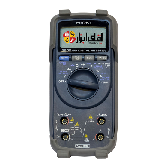
1.2 各部の名称と機能 1.2 各部の名称と機能 正面図 表示部 参照 : ( p.13) キー操作部 参照 : ( p.14) ファンクション スイッチ 参照 : ( p.14) μA.mA 端子 電流測定(999.9 mA 以下) 、 温度測 定(T2+)で使用 する端子です。テ ストリードの赤色 を接続します。 Ω. 端子 A 端子 COM 端子 電圧測定、ダイオード... - Page 17 1.2 各部の名称と機能 表示部 測定値表示 部と単位 バーグラフ 記号 説明 オートパワーセーブ機能が ON のとき点灯します。 相対値表示機能が ON のとき点灯します。 レコーディング機能が ON のとき点灯します。 最大値を表示しているとき点灯します。 ( レコーディング機能) 最小値を表示しているとき点灯します。 ( レコーディング機能) MAX- 最大値 - 最小値を表示しているとき点灯します。 (レコーディ ング機能) 平均値を表示しているとき点灯します。 ( レコーディング機能) ダイオードチェックファンクションのとき点灯します。 導通チェックファンクションのとき点灯します。 バッテリマーク(電池消耗警告表示)です。 電池交換時期に点灯します。 高調波 % 表示機能が ON のとき点灯します。 AUTO オートレンジのとき点灯します。...
- Page 18 1.2 各部の名称と機能 ファンクションスイッチ 本器の電源を切ります。 電圧測定ファンクションです。 キーで DC、AC、Hz を切り替えます。 SHIFT ダイオードチェックファンクションです。 抵抗測定ファンクションです。 キーで導通チェックに切り替えます。 SHIFT 静電容量測定ファンクションです。 9999 μA 以下の電流測定ファンクションです。 キーで DC、AC、Hz を切替えます。 SHIFT 999.9 mA 以下の電流測定ファンクションです。 キーで DC、AC、Hz を切り替えます。 SHIFT 9.99 A 以下の電流測定ファンクションです。 キーで DC、AC、Hz を切り替えます。 SHIFT 温度測定ファンクションです。 キーで測定チャ SHIFT ンネル T1、T2、⊿ T を切り替えます。 キー操作部...
- Page 19 1.2 各部の名称と機能 ホルスタ コネクタ テストリード ホルダ スタンド オプションの通信ケーブルを接続します。 コネクタ ホルスタを本器から外すとコネクタも外れます。紛 失しないように注意してください。 テストリードを固定できます。 テストリード 一方のテストリードを固定して、本器を持ちながら ホルダ 測定することができます。 スタンドを引き出して、本器を立てて置くことがで スタンド きます。 本器は標準付属のホルスタが装着されています。 ホルスタは柔らかい材質のため、外部からの衝撃を吸収して本 器を保護します。 電池またはヒューズは、ホルスタを外してから交換してくださ い。また、交換後はホルスタを装着してから使用してください。...
- Page 20 1.2 各部の名称と機能 背面 通信ポート ネジ スタンドを立てたまま、上方向から強い力を加えないでくださ い。スタンドを損傷します。...
- Page 21 1.2 各部の名称と機能 L9207-10 テストリード バリア キャップ 黒 赤 プラグ ケーブル 先ピン 被測定物に接続します。 先ピン 長さ キャップ装着時 4 mm 以下 (プローブチップ) キャップ未装着時 19 mm 以下 (金属ピン) 太さ 約 2 mm キャップ 先ピンにキャップを装着して短絡事故を防止します。 バリア 先ピンからの安全距離を示します。 二重被服ケーブルです。 ケーブル 長さ 約 900 mm 太さ 約 3.6 mm プラグ 本体の測定端子に接続します。 •...
- Page 22 1.2 各部の名称と機能 • キャップを装着して測定する場合、キャップを損傷しないよ うに注意してください。 • 測定中に不用意にキャップが外れた場合などは、感電事故を 防ぐため取り扱いには十分注意してください。 キャップの脱着方法 金属ピンの先端は尖っていますので、けがに注意してください。 キャップを取り外す キャップを装着する キャップの根元を キャップの穴にテ 軽くつまんで、引 ストリードの金属 き 抜 い て く だ さ ピンを通して、奥 い。取 り 外 し た まで確実に押し込 キャップは、無く んでください。 さないように保管 してください。...
-
Page 23: 第 2 章 測定方法
測定方法 第 2 章 感電事故を防ぐため、下記のことをお守りください。 • 測定前に必ずファンクションスイッチの位置を確認してくだ さい。 • ファンクションスイッチを切り替えるときは、テストリード を被測定物から外し、測定端子からも抜いてください。 • 最大入力電圧は DC1000 V、AC1000 V または 2 × 10 V Hz です。この最大入力電圧を超えると本器を破損し、人 身事故になるので測定しないでください。 • 最大入力電流は以下の通りです。 A 端子:AC/DC 10 A まで連続 μ A.mA 端子:AC/DC 1 A この電流を超えると本器を破損し、人身事故になるので入力 しないでください。 • 対地間最大定格電圧は以下の通りです。 CAT Ⅱ:DC1000 V, AC1000 V CAT Ⅲ:DC600 V, AC600 V 大地に対してこの電圧を超える測定はしないでください。本... -
Page 24: 測定前の点検
2.1 測定前の点検 安全のため、テストリードは付属またはオプションの テスト リードを使用してください。 テストリードには輸送時にプラグを保護する ためのキャップが装着されています。ご使用 前に取り外してください。 2.1 測定前の点検 動作点検 動作確認をして異常があった場合は、 途中でも点検を中止し、 本 器を使用しないでください。 用意するもの • 本器 • L9207-10 テストリード • AC コンセント(AC100 V 50 Hz/ 60 Hz などの商用電源) ファンクションスイッチを Ω にします。 キ ー を 押 し て 導 通 チ ェ ッ ク に し ま す。 SHIFT (... - Page 25 2.1 測定前の点検 テストリードの赤色と黒色の先端同士を押し当て て短絡します。 • ブザーが鳴る • 0 Ω 付近で値が安定している → を表示する / 表示が安定しない→ NG • テストリードの断線、テスタの故障が考え られます ファンクションスイッチを V にし、SHIFT キーを 押して ACV にします。 ( 点灯) AC コンセントの差し込み口にテストリードの先 端を差し込みます。 黒 赤 • 商用電圧値を表示する → • 商用電圧値を表示しない→ NG テスタの故障が考えられます これは本器の動作の一部を確認するのみです。 本器が製 品仕様通り動作するかの確認には、...
- Page 26 2.1 測定前の点検 (μA、mA 端子用ヒューズの断線確認) ファンクションスイッチをダイオードチェック ( )にします。 テストリードの赤色を μA、mA 端子に、黒色を V 端子に接続し、先端同士を押し当てて短絡します。 • 約 1.6 V を表示する → • OL を表示する→ NG ヒューズの断線が考えられます ヒューズの交換をしてください 参照 :( p.65) (A 端子用ヒューズの断線確認) テストリードの赤色を A 端子に、 黒色を V 端子に 接続し、先端同士を押し当てて短絡します。 • ブザーが鳴る → を表示する→...
-
Page 27: 電圧測定
2.2 電圧測定 2.2 電圧測定 • 各レンジの測定範囲を超える電圧、電流を入力しないでくだ さい。本器を破損します。 • 本器の電源が OFF の状態で、測定端子に電圧、電流を入力し ないでください。本器を破損することがあります。 ファンクションスイッチを 切り替えます。 キーで DC、 AC を選 SHIFT 択します。 (AC) (DC) Hz ( 周波数 ) <例> ACV 選択時 マニュアルレンジにしたい 場合は キーを押し RANGE (AUTO 消灯) ます。 (通常はオートレンジです) p.34) 赤 テストリードを測定端子に 接続します。... -
Page 28: 電流測定
2.3 電流測定 被測定物にテストリードを 交流電圧測定 <例> 接続します。 黒 赤 直流電圧測定 赤 黒 表 示 部 の 表 示 値 を 読 み ま す。 <例> AC 電圧測定時 周波数を見たいときは SHIFT キー を押して Hz(周波数)を 選択します。( p.30) 高調波 % 表示を見たいときは キー を長押しします。 SHIFT 参照 :( ... - Page 29 2.3 電流測定 ファンクションスイッチを 切り替えます。 μA:9999 μA 以下を測定す るとき mA :999.9 mA 以下を測定す るとき A : 9.99 A以下で測定すると き 測定する電流が不明なときは、 A に合わせてください。 キーで DC、 AC を選 SHIFT <例> ACA 選択時 択します。 (DC) (AC) Hz(周波数) マニュアルレンジにしたい (AUTO 消灯) 場合は キーを押し RANGE ます。 (通常はオートレンジです) 参照...
-
Page 30: 抵抗測定
2.4 抵抗測定 2.4 抵抗測定 電圧を入力しないでください。本器を破損し、人身事故になり ます。電気事故を防ぐため、測定回路の電源を切ってから、測 定してください。 ファンクションスイッチを 切り替えます。 マニュアルレンジにしたい 場合は キーを押し RANGE (AUTO 消灯) ます。 (通常はオートレンジです) 参照 :( p.34) 赤 テストリードを測定端子に 接続します。 黒 <例> 被測定物にテストリードを 接続します。 黒 赤 表示部の表示値を読みます。 • 相対値表示機能 (REL) でゼロアジャストすることがで きます。 参照 : ( p.39) •... -
Page 31: 導通チェック
2.5 導通チェック 2.5 導通チェック 電圧を入力しないでください。本器を破損し、人身事故になり ます。電気事故を防ぐため、測定回路の電源を切ってから、測 定してください。 ファンクションスイッチを 切り替えます。 キーで導通( )を SHIFT 選択します。 点灯 レンジを変更したい場合は キーを押します。 RANGE (AUTO 消灯) (通常はマニュアルレンジです) オ ー ト レ ン ジ に し た い 場 合 は キーを長押しします。 RANGE 参照 :( p.34) 赤 テストリードを測定端子に... -
Page 32: ダイオードチェック
2.6 ダイオードチェック 2.6 ダイオードチェック 電圧を入力しないでください。本器を破損し、人身事故になり ます。電気事故を防ぐため、測定回路の電源を切ってから、測 定してください。 ファンクションスイッチを 切り替えます。 テストリードを測定端子に 接続します。 赤 黒 被測定物にテストリードを <例> 接続します。 カソード アノード 表示部の表示値を読みます。 順方向 正常なダイオードで順方向電圧 (0.3 ~ 0.8 V)を表示します。 黒 赤 表示値が 0.050 V 未満の場合、 ブザー音が鳴ります。 表示値が 0.3 V ~ 0.8 V に下が る と ダ イ オ ー ド 検 出 と し て ブ ザー単発音が鳴ります。... -
Page 33: コンデンサ容量測定
2.7 コンデンサ容量測定 2.7 コンデンサ容量測定 電圧を入力しないでください。本器を破損し、人身事故になり ます。電気事故を防ぐため、測定回路の電源を切ってから、測 定してください。 ファンクションスイッチを 切り替えます。 マニュアルレンジにしたい 場合は キーを押し RANGE (AUTO 消灯) ます。 (通常はオートレンジです) 参照 :( p.34) 赤 テストリードを測定端子に 接続します。 黒 被測定物にテストリードを <例> 接続します。 表示部の表示値を読みます。 本器は充放電方式により、コン デンサ容量を測定します。 9.999 mF レンジは、充電時間の影響 で測定値が表示されるまで数十 秒程度かかる場合があります。... -
Page 34: 周波数測定
2.8 周波数測定 2.8 周波数測定 • 各レンジの測定範囲を超える電圧、電流を入力しないでくだ さい。本器を破損します。 • 本器の電源が切れている状態で、測定端子に電圧、電流を入 力しないでください。本器を破損することがあります。 • 周波数測定範囲を超える周波数信号を測定した場合、表示が ゼロになりますので注意してください。 ファンクションスイッチで V、μA、mA、A を選択し ます。 キーで Hz ( 周波数) を SHIFT 選択します。 (Hz 点灯) 電 圧 ま た は 電 流 レ ン ジ を 変 更 し た い 場 合 は RANGEキー <例>... -
Page 35: 温度測定
2.9 温度測定 2.9 温度測定 電圧を入力しないでください。本器を破損し、人身事故になり ます。電気事故を防ぐため、測定回路の電源を切ってから、測 定してください。 • 温度プローブ先端に過度の衝撃を加えたり、リード線を無理 に曲げないでください。故障や断線の原因になります。 • 温度プローブの握り部および補償導線が指定の温度範囲を超 えないよう注意してください。 • 被測定物の表面をきれいにして、温度プローブが確実 に当たるようにしてください。 • 外気温度以上を測定するときは、最大温度読値が得ら れるまで温度プローブを被測定物の表面で動かしてく ださい。 • 外気温度以下を測定するときは、最小温度読値が得ら れるまで温度プローブを被測定物の表面で動かしてく ださい。... - Page 36 2.9 温度測定 熱電対センサ(K または J ま たは mV)を選択します。 参照 :( p.48) ※mVを選択すると熱起電力を表 示します。 ファ ンクショ ンスイ ッチを 切り替えます。 ⊿ SHIFTキーで測定チャンネル (T1、 T2、 ⊿ T) を選択します。 T1:測定チャネル 1 表示 赤 赤 T2:測定チャネル 2 表示 ⊿ T:T1-T2 の温度差表示 黒 黒 温度 プローブ を測定 端子に 接続します。...
-
Page 37: 第 3 章 付加機能
3.1 オートレンジ機能 付加機能 第 3 章 3.1 オートレンジ機能 オートレンジ機能は、最適なレンジを自動で選択して測定しま す。入力信号の大きさがわからないときや、レンジ設定の手間 を省きたいときに使用します。 導通チェック以外のファンクションでは、電源を入れるとオー トレンジになります。 (画面に「AUTO」が点灯します) AUTO 点灯 しきい値 レンジ アップ ダウン フルスケール 9999 レンジ 9999 超 900 未満 9999 9.99 A レンジ - - 2.100 V レンジ - - 2100 • 導通チェックファンクションでは、初期設定がマニュ アルレンジになります。... -
Page 38: マニュアルレンジ機能
3.2 マニュアルレンジ機能 3.2 マニュアルレンジ機能 キーを押すとマニュアルレンジになります。 キーを押す RANGE ごとにレンジアップし、小数点の位置が変わります。入力信号 の大きさがあらかじめわかっているときに使用します。 オートレンジにしたいときは、RANGE キーを長押しします。 AUTO 消灯 • 導通チェックの初期設定はマニュアルレンジです。導 通チェック以外のファンクションでは、初期設定が オートレンジになります。 • ダイオードチェック、A ファンクション、温度測定に はオートレンジはありません。 • Hz はオートレンジのみです。... -
Page 39: ホールド機能
3.3 ホールド機能 3.3 ホールド機能 3.3.1 トリガホールド機能 トリガホールド機能は、REC/HOLD キーを押す毎に、測定値を 固定します。 リフレッシュホールド機能を OFF にします。 参照 :( p.49) 測定時に キーを押すと、 表示値を固定 REC/HOLD します。 キーを押すごとに表示値を更新して固 REC/HOLD 定します。 HOLD 点灯 HOLD 点滅→点灯 トリガホールドを解除するときは、REC/HOLD キーを長押しします。 バーグラフは表示値に従い固定されます。... -
Page 40: リフレッシュホールド機能
3.3 ホールド機能 3.3.2 リフレッシュホールド機能 リフレッシュホールド機能は、測定値が安定すると自動的に表 示値を固定します。テストリードを被測定物から離しても表示 値は固定されたままのため、測定場所から表示値が見づらいと きや両手で測定しているときに便利な機能です。 リフレッシュホールド機能のしきい値(表示が安 定したと判断する変化量)を設定します。 参照 :( p.49) キーを押すと、トリガ待ち状態になり REC/HOLD ます。 測定対象にテストリードを接続します。表示値が 安定すると が点灯し、 ブザー音が鳴り表示が HOLD 固定されます。 HOLD 点滅 トリガ待ち状態 ブザー音を確認後、テストリードを測定対象から 離します。 表示値は固定されたまま、 が点滅し、再びト HOLD リガ待ち状態になります。 キーを長押しすると、リフレッシュ REC/HOLD ホールド機能を解除します。... -
Page 41: レコーディング機能
3.4 レコーディング機能 • バーグラフは入力信号に従います。 • 表示値が限度感度値 を超えないと表示値は固定され ません。表示値がうまく固定されないときは、しきい 値を変更してみてください。 参照 : ( p.49) * 限度感度値は各ファンクションで以下のようになっています。 ファンクション 限度感度値 DCV/DCμA/DCmA 各レンジ 100 カウント ACV/ACμA/ACmA 各レンジ 500 カウント 0.1 A 0.5 A Ω 3.4 レコーディング機能 レコーディング機能開始からの入力信号の最大値、 最小値、 最大値 - 最小 値、平均値を記録します。 入力信号の現在値 :REC 入力信号の最大値... - Page 42 3.4 レコーディング機能 キーを押す度に最大値、最小値、最大 REC/HOLD 値 - 最小値、平均値、現在値と表示部が切り替わ ります。 MAX 点灯 最大値表示 MAX-MIN 現在値 最大値 (最小値) を更新するとブザー音が鳴ります。 キーを長押しすると、レコーディング REC/HOLD 機能を解除します。 • レコーディング機能では、表示値ではなく、平滑する 前の内部測定データに対して最大値、最小値、平均値 を記録します。 • レコーディング機能では、オートパワーセーブ機能は 自動的に無効になります。 • バーグラフは現在値を示します。...
-
Page 43: 相対値(Rel)表示機能
3.5 相対値(REL)表示機能 3.5 相対値(REL)表示機能 キーを押すと、現在の表示値を基準値として、その相対値 を表示します。 電圧(mV)測定、抵抗測定などで測定前にテストリードを短絡 して相対値表示モードにすることで、ゼロアジャスト機能とし て利用できます。 (熱起電力や配線抵抗の影響をキャンセルしま す) 基準値にしたい測定値を表示します。 キーを押すと、 現在の表示値を基準値として、 その相対値を表示します。 相対値 = 測定値 - 基準値 • バーグラフは表示する相対値に従います。 • 表示が「OL」の場合は、相対値(REL) 表示機能は動 作しません。... -
Page 44: Ma(0-20 Ma)% 換算表示機能
3.6 4-20 mA(0-20 mA)% 換算表示機能 3.6 4-20 mA(0-20 mA)% 換算表示 機能 4-20 mA(0-20 mA)% 換算表示機能は、計装システムの 4- 20 mA(または 0-20 mA)信号を 0% ~ 100% に換算して表 示します。 4-20 mA (測定電流 12.00 mA 時) 測定値 [mA] - 4[mA] % 換算値= × 100[%] 16[mA] パワーオン... -
Page 45: バーグラフ表示機能
3.7 バーグラフ表示機能 3.7 バーグラフ表示機能 測定値に応じてバーが点灯し、直感的に入力レベルが確認でき ます。測定機能に応じてスケール(目盛)を表示します。また 極性に応じて±符号を表示します。 スケール スケール バー バー 3.8 オートパワーセーブ機能 ファンクションスイッチまたはキーの最終操作から設定時間が 経過するとオートパワーセーブ機能が動作します。 オートパワー セーブ機能により表示画面が消灯し、 本体内部の電源消費を抑え ます。 APS 点灯 パワーオンオプションで動作時間を設定します。 機能を無効にすることもできます。 参照 :( p.49) オートパワーセーブ機能から復帰するには、ロー タリスイッチを一度 OFF するか、 何かキーを押し ます。 • レコーディング機能では、オートパワーセーブ機能は 無効になります。 • オートパワーセーブ機能を無効にした場合は、電源の 切り忘れに注意してください。... -
Page 46: 過負荷警告機能
3.9 過負荷警告機能 3.9 過負荷警告機能 電圧測定で入力電圧が 610.0 V を超えると、断続的なブザー音 で警告します。ただちにテストリードを被測定物から外してく ださい。 ピッピッピ… ブザー断続音 各レンジでフルスケールを超えると「OL」を表示しま す。 オートレンジにするか最適なレンジを選択してくだ さい。 参照 : ( p.33)( p.34) レンジ フルスケール 9999 カウントレンジ 9999 9.99 A レンジ 9.99 A 2.100 V カウントレンジ 2.100 V 3.10 電池寿命警告機能 点滅... -
Page 47: 通信機能(オプション
3.11 通信機能(オプション) • バッテリマーク( )が表示されてもしばらくは測定値を表 示しますが、バッテリマーク( )点灯中は確度仕様を満足 しませんので、速やかに電池を交換してください。 参照 :( p.65) 3.11 通信機能(オプション) 本器は、 RS-232C インターフェースを利用したデータの送信機 能を装備しています。パソコンと本器を接続して、測定データ を本器からパソコンに転送し、データの記録と保存ができます。 この機能を利用するには、 下記の別売りオプションが必 要です。 • パソコン側 USB ポートに接続する場合 3856-02 通信パッケージ(USB) 参照 : 3856-02 取扱説明書 パソコンにソフトウェアをインストールします。 参照 :3856-02 取扱説明書 本器の通信設定は以下となっています。必要に応 じてパソコン側の設定を行ってください。 ボーレート 9600 パリティチェック... - Page 48 3.11 通信機能(オプション) 通信ケーブルの光コネクタ側を本体ホルスタのコ ネクタ部に接続します。 「RS-232C INTERFACE」 の文字を上に向ける 「RS-232C INTERFACE」の文字を下に向けると通信で きません。 通信ケーブルのもう一方のコネクタをパソコンに 接続します。 ソフトウェアを実行します。本器からパソコンに 測定データが送信されます。 コネクタを本器から外す場合はツメを押しながら引き 抜きます。 ツメ...
-
Page 49: 高調波 % 表示機能
3.12 高調波 % 表示機能 3.12 高調波 % 表示機能 高調波 % 表示機能は、換算式により入力信号波形の高調波比率 (H%)を求め表示します。高調波比率が高いほど基本波に対し 高調波を多く含んだ波形となります。 正弦波の場合は 0%、 方形 波の場合は 11.1% となります。 ファンクションスイッチを V にします。 キーを長押しすると高調波 % 表示機能が起 SHIFT 動します。 キーを再び長押しすると高調波 % 表示機能 SHIFT を解除します。 キーを押すと、 約 3 秒間入力電圧を表示し RANGE ます。 * 電圧のレンジは変更できません。 (電圧はオートレンジ のみです。... -
Page 50: 温度スキャン表示機能
3.13 温度スキャン表示機能 3.13 温度スキャン表示機能 温度測定で各測定チャンネル T1、T2 の温度及び温度差⊿ T を 順次繰返して表示します。 ⊿ ファンクションを TEMP にします。 キーを長押しすると温度スキャン表示機能 SHIFT が起動します。 キーを再び長押しすると温度スキャン表示 SHIFT 機能を解除します。 バーグラフは基準接点温度を示します。 3.14 表示バックライト機能 周囲が暗くて表示が見難い場合に、表示バックライト機能で表 示部を明るくします。 キーを長押しするとバックライトが点灯しま す。 パワーオプションで設定した時間が経過すると自 動的に消灯します。 参照 :( p.49) キーを点灯中に長押しするとバックライトが 消灯します。... -
Page 51: 第 4 章 パワーオンオプション
パワーオンオプション 第 4 章 測定機能、付加機能の各種設定を行います。 操作方法 +電源 ON SHIFT 設定項目の選択 設定値 (パラメータ) の選択 設定値 (パラメータ) の確定 キーを押しながらファンクションスイッチ SHIFT を OFF から回して電源を入れると設定画面となり ます。 キーを押して設定項目を選択します。 SHIFT キーまたは キーを押して設定値 REC/HOLD (パラメータ)を選択します。 (現在設定されてい る値以外は表示が点滅します。 ) キーを押して設定値 (パラメータ) を確定 RANGE します。 設定が完了したらファンクションスイッチを OFF します。 (または、RANGE キーを長押しすると通... - Page 52 設定項目一覧 設定項目 設定画面 機能 通信機能:応答の設定 応答を ON にすると通信機能で本器 応答 が受信した文字を全て返信します。 (設定項目)OFF(初期値)/ ON 通信機能:データ出力の設定 データ出力を ON にすると通信機能 データ出力 で本器からサンプリング毎にデータ のみを出力します。 (設定項目)OFF(初期値)/ ON 4-20 mA (0-20 mA) % 換算表示機 4-20mA 能の 4-20 mA と 0-20 mA 表示の切 (0-20mA)% り替えを行います。 換算表示 (設定項目) :4-20 mA%(初期値) /0-20 mA% Hz(周波数)の最小周波数を設定し...
- Page 53 リフレッシュホールド機能のしきい 値(表示が安定したと判断する変化 量)を設定します。OFF を選択する リフレッシュ と リ フ レ ッシ ュ 機 能 を 無 効 に し ま ホールド す。 (トリガホールド機能が有効) (設定項目)OFF(初期値)/100 ~ 1000(100 毎に設定) オートパワーセーブ機能が動作する までの時間を設定します。 オートパワー (設定項目)15m(初期値)/1m ~ セーブ 99m/OFF 表示バックライトが自動消灯するま での時間を設定します。 表示 (設定項目)15s(初期値)/1 ~ バックライト 99/OFF 電圧ファンクション、または電流測...
- Page 54 パワーオンオプション設定画面一覧 キーを押す毎に設定画面が切り替わります。 SHIFT データ出力 4-20 mA 応答 (0-20 mA)% 換算表示 熱電対タイプ ブザー音設定 最小周波数 リフレッシュ オートパワー 表示 ホールド セーブ バックライト AC/DC 初期化 起動選択...
-
Page 55: 第 5 章 仕様
5.1 一般仕様 仕様 第 5 章 5.1 一般仕様 測定機能 • 直流電圧 • 交流電圧 • 直流電流 • 交流電流 • 抵抗 • 導通 • ダイオード • 静電容量 • 周波数 • 温度 付加機能 • オートレンジ機能(AUTO) • マニュアルレンジ機能 • トリガホールド機能( ) HOLD • リフレッシュホールド機能( )... - Page 56 5.1 一般仕様 表示 • データ表示 4 桁 最大カウント [9999] 最大カウント [999] 10 A レンジ 極性表示 [-] マーク自動点灯 オーバレンジ表示 [OL] または [-OL] • バーグラフ スケール表示、41 ドットバー表示、±極性表示 • 単位、記号 [ ℃ ][H%][m][μ][A][V][F][%][M][k][Ω][Hz][APS] [REL][REC][MAX][-][MIN][AVG][ [AUTO][ ][T1][T2] HOLD [ ⊿ T][SCAN][RS232] レンジ切り替え オートレンジまたはマニュアルレンジ 入力端子 V.Ω.
- Page 57 5.1 一般仕様 μA.mA 端子用 1 A/700 V ヒューズ 交換部品 (遮断容量 50kA、SIBA 社製速断型 φ6.35 × 32 mm 7012540) A 端子用 10 A/600 V ヒューズ (遮断容量 10kA、バスマン社製速断型 φ6.35 × 25.35mm TDC600) オプション 3853 携帯用ケース 3856-02 通信パッケージ(USB) 9180 シース形温度プローブ 9181 表面形温度プローブ 9182 シース形温度プローブ 9183 シース形温度プローブ...
-
Page 58: 電気的特性
5.2 電気的特性 5.2 電気的特性 ノイズ除去 DCV…60 dB 以上(50 Hz / 60 Hz) NMRR DCV…120dB 以上 ノイズ除去 (DC / 50 Hz / 60 Hz、1kΩ unbalance) CMRR ACV…60dB 以上 (DC / 50 Hz / 60 Hz、1kΩ unbalance) DCV…1.2s 以内(0V → 200 V オートレンジ動作) 応答時間... - Page 59 5.3 確度 5.3 確度 弊社では測定値の限界誤差を、次に示す f.s.(フルスケール)、 rdg.(リーディング) 、dgt.(デジット)に対する値として定義 しています。 rdg.(読み値、表示値、指示値) 現在測定中の値、測定器が現在指示している値を表します。 dgt.(分解能) ディジタル測定器における最小表示単位、 つまり最小桁の "1" を 表します。 確度保証電源 10.2 V から マーク点灯まで 電圧範囲 確 度 保 証 温 湿 度 23 ℃± 5 ℃、80%rh 以下(結露なし) 範囲 確度保証期間 1 年間 温度特性 測定確度×...
- Page 60 5.3 確度 AC V(交流電圧) 確度 入力イン レンジ 過負荷保護 500- ピーダンス 500Hz 1kHz 2kHz Ω 11.11 M ± 2.5%rdg 規定なし 規定なし ± 1% 999.9 mV ± 5dgt. *2 100 pF 以下 DC1000 V / Ω 10.10 M ± 1%rdg. ±1%rdg. ± 2%rdg. AC1000 V 9.999 V ±...
- Page 61 5.3 確度 抵抗 Ω /導通 レンジ 確度 測定電流 開放電圧 過負荷保護 ± 0.3%rdg. 約 0.46 Ω 999.9 ± 3 dgt. *1 ± 0.3%rdg. 約 155 μA Ω 9.999 k ± 3 dgt. *1 DC1000 V / ± 0.3%rdg. AC1000 V Ω 約...
- Page 62 5.3 確度 直流電流 DCA レンジ 確度 負荷電圧 シャント抵抗 過負荷保護 ± 0.1%rdg. μ Ω 999.9 0.11 V ± 3 dgt. ± 0.1%rdg. μ 9999 1.1 V Ω ± 3 dgt. 1 A/700 V ヒューズ 遮断容量 50 kA ± 0.2%rdg. Ω 99.99mA 0.17 V ±...
- Page 63 5.3 確度 温度 TEMP 熱電対タイプ レンジ 確度 -40 ~ 1372 ℃ ± 0.3%rdg. ± 3 ℃ -40 ~ 1200 ℃ 確度は温度プローブの誤差を含まず 応答時間:60 分(本体基準接点温度補償安定時間) 表示更新レート:7 回/ s 周波数 Hz レンジ 確度 最小周波数 *1 過負荷保護 ± 0.03%rdg. 9.999 Hz ± 3dgt. ± 0.03%rdg. 99.99 Hz ±...
- Page 64 5.3 確度 最小感度電圧(rms) 2 kHz-15 kHz 確度規定 レンジ (正弦波) 15 kHz- 最大電圧 40 Hz-5 kHz 10 Hz-20 kHz 50 kHz (方形波) 規定なし 999.9 V 90 V 100 V 1000 V ※最小感度電流(周波数 Hz) 正弦波 方形波 レンジ 20 Hz-20 kHz 10 Hz-20 kHz 50 μA 999.9 μA 50 μA...
-
Page 65: L9207-10 テストリード仕様
5.4 L9207-10 テストリード仕様 5.4 L9207-10 テストリード仕様 使用場所 屋内使用、汚染度 2、高度 2000 m 使用温湿度範囲 -15 ℃~ 55 ℃、90%rh 以下 結露なし 保存温湿度範囲 -30 ℃~ 60 ℃、90%rh 以下 結露なし 最大定格 キャップ装着時 対地間最大定格電圧 1000 V 測定カテゴリⅢ 予想される過渡過電圧 8000 V 対地間最大定格電圧 600 V 測定カテゴリⅣ 予想される過渡過電圧 8000 V キャップ未装着時 対地間最大定格電圧... - Page 66 5.4 L9207-10 テストリード仕様...
-
Page 67: 第 6 章 保守・サービス
6.1 困ったときは 保守・サービス 第 6 章 6.1 困ったときは • 故障と思われるときは、 「修理に出される前に」( p.64) を確 認してから、お買上店(代理店)か最寄りの営業所にご連絡 ください。 • 本器の調整や修理は、危険を良く知った技能者の責任で行っ てください。 • 本器を輸送するときは、 輸送中に破損しないように梱包し、 故 障内容も書き添えてください。輸送中の破損については保証 しかねます。 • 改造は絶対にしないでください。また修理技術者以外の人は、 分解や修理をしないでください。火災や感電事故、けがの原 因になります。 • 本器の保護機能が破損している場合は、使用できないように 廃棄するか、知らないで動作させることのないように、表示 しておいてください。 本器の確度維持あるいは確認には、定期的な校正が必要です。 修理・校正業務のご用命は、 「日置エンジニアリングサービス (株)」ま でお願いいたします。 (TEL 0268-28-0823、FAX 0268-28-0824)... - Page 68 6.1 困ったときは 修理に出される前に 動作がおかしいとき、以下の項目をチェックしてください。 症状 チェック項目 参照ページ 電池が消耗していませんか? ( p.65) → 電池を交換してください。 画面に表示が 電池スナップのケーブルが断線してい でない ませんか? → お買上店(代理店)か最寄りの営業 所にご連絡ください。 電池が消耗していませんか? ( p.65) → 電池を交換してください。 画面の表示が オートパワーセーブ機能が動作してい しばらくする ませんか? と消える ( p.41) →オートパワーセーブの設定を確認し てください。 表示が一部表 全点灯表示で表示欠けがありますか? ( p.67) 示されない →修理 ヒューズが断線していませんか? ヒューズの断線確認をしてください。...
-
Page 69: クリーニング
6.2 クリーニング 6.2 クリーニング 本器の汚れをとるときは、柔らかい布に水か中性洗剤を少量含 ませて、軽くふいてください。ベンジン、アルコール、アセト ン、エーテル、ケトン、シンナー、ガソリン系を含む洗剤は絶 対に使用しないでください。変形、変色することがあります。 表示部は乾いた柔らかい布で軽く拭いてください。 6.3 電池およびヒューズの交換 • 感電事故を避けるため、 ファンクションスイッチをOFF にし、 テストリードを外してから電池を交換してください。 交換後 は、必ずカバーをしてから、ネジ留め後に使用してください。 • 極性+-に注意し、逆挿入しないでください。性能劣化や液 漏れの原因になります。また必ず指定の電池と交換してくだ さい。 • 使用済の電池をショート、充電、分解または火中への投入は しないでください。破裂する恐れがあり危険です。 • 使用済の電池は地域で定められた規則に従って処分してくだ さい。 • 感電事故を避けるため、 ファンクションスイッチを OFF にし、 テストリードを外してからヒューズを交換してください。 交換 後は、 必ずカバーをしてから、 ネジ留め後に使用してください。 • ヒューズは、指定された形状と特性、定格電流、電圧のもの を使用してください。指定以外のヒューズを用いたりヒュー... - Page 70 6.3 電池およびヒューズの交換 用意するもの : プラスドライバー テストリードを本器から外 し、 ファンクションスイッチ を OFF にします。 本器からホルスタを外しま す。 プラスドライバで下ケース ネジ のネジを外します(3か所) 。 次 に 下 ケ ー ス を 外 し ま す。 (下側から外します。上側は つめで勘合しています。 ) 電池(6F22(マンガン)ま たは 6LR61(アルカリ) ) 、 またはヒューズを交換しま す。 指定ヒューズ μA.mA 端子用 :1 A/700 V ヒューズ (遮断容量...
-
Page 71: 本体ソフトのバージョンの確認方法
6.4 本体ソフトのバージョンの確認方法 6.4 本体ソフトのバージョンの確認方法 以下の方法で本体ソフトのバージョン No. を確認することがで きます。 キーを押しながら電源を入れます。 ブザー音と同時に キーを離します。 メイン画面にバージョン No. が表示されます。 2.00 この画面ではバージョン No.「 」です。 任意のキーを押すと測定画面になります。 6.5 全点灯表示の確認方法 以下の方法で本体表示を全点灯させたまま表示を確認すること ができます。 キーを押しながら電源を入れます。 REC/HOLD ブザー音と同時に キーを離します。 REC/HOLD 全点灯して表示します。 任意のキーを押すと測定画面になります。... - Page 72 6.5 全点灯表示の確認方法...
- Page 73 3805-50...
- Page 75 3415 3415-01 3805-50 3415-02 TEMPERATURE DIGITAL HiTESTER XXXX 製品名 HiTESTER INSTRUCTION MANUAL...
- Page 77 Contents Contents Introduction ............... 1 Verifying Package Contents........1 Safety Information............. 3 Operating Precautions ..........6 Chapter 1 Overview Product Overview/ Features...... 11 Names and Functions of Parts ....12 Chapter 2 Measurement Pre-Operation Inspection ......23 Voltage Measurement ....... 26 Current Measurement .......
- Page 78 Contents Chapter 3 Additional Functions Auto Range Function ........ 37 Manual Range Function ......38 Hold Functions .......... 39 3.3.1 Trigger Hold Function ....39 3.3.2 Refresh Hold Function ....40 Recording Function ........41 Relative (REL) Display Function ....43 4-20 mA (0-20 mA) Percentage Display Function........
- Page 79 Contents Chapter 5 Specifications General Specifications ......55 Electrical specifications ......58 Accuracy............ 59 L9207-10 TEST LEAD Specifications ..65 Chapter 6 Maintenance and Service Troubleshooting......... 67 Cleaning ............ 69 Replacing the Battery and Fuses ....69 Checking the Instrument Software Version71 Displaying All On-Screen Items....
- Page 80 Contents...
-
Page 81: Introduction
Introduction Thank you for purchasing the HIOKI “Model 3805-50 DIGITAL HiTESTER.” To obtain maximum performance from the instru- ment, please read this manual first, and keep it handy for future reference. Verifying Package Contents • When you receive the instrument, inspect it carefully to ensure that no damage occurred during shipping. - Page 82 Options 3853 CARRYING CASE 3856-02 COMMUNICATION PACKAGE (USB) 9180 SHEATH TYPE TEMPERATURE PROBE 9181 SURFACE TEMPERATURE PROBE 9182 SHEATH TYPE TEMPERATURE PROBE 9183 SHEATH TYPE TEMPERATURE PROBE 9472 SHEATH TYPE TEMPERATURE PROBE 9473 SHEATH TYPE TEMPERATURE PROBE 9474 SHEATH TYPE TEMPERATURE PROBE 9475 SHEATH TYPE TEMPERATURE PROBE 9476...
-
Page 83: Safety Information
Safety Information This instrument is designed to comply with IEC 61010 Safety Standards, and has been thoroughly tested for safety prior to ship- ment. However, mishandling during use could result in injury or death, as well as damage to the instrument. Be certain that you understand the instructions and precau- tions in the manual before use. - Page 84 The following symbols in this manual indicate the relative impor- tance of cautions and warnings. Indicates that incorrect operation presents an extreme hazard that could result in seri- ous injury or death to the user. Indicates that incorrect operation presents a significant hazard that could result in serious injury or death to the user.
- Page 85 Measurement categories (Overvoltage categories) This instrument complies with CAT II (1000 V) and CAT III (600 V) safety requirements. To ensure safe operation of measurement instruments IEC 61010 establishes safety standards for various electrical envi- ronments, categorized as CAT I to CAT IV, and called measure- ment categories.
-
Page 86: Operating Precautions
Operating Precautions Follow these precautions to ensure safe operation and to obtain the full benefits of the various functions. Setting up the Instrument Operating temperature and humidity: 0 to 40°C (32 ± 122°F), 80%RH or less (non-condensating) In the event that the temperature exceeds 31°C (88°F), linearly decrease the humidity to 40°C at 50%rh. - Page 87 Before using the instrument the first time, verify that it operates normally to ensure that the no damage occurred during storage or shipping. If you find any damage, contact your dealer or Hioki representative. Before using the instrument, check that the...
- Page 88 Handling this Instrument To avoid damage to the instrument, protect it from physical shock when transporting and handling. Be especially careful to avoid physical shock from dropping. • To avoid corrosion from battery leakage, remove the batteries from the instrument if it is to be stored for a long time.
- Page 89 • To avoid breaking the cables, do not bend or pull them. • The ends of the leads are sharp. Be careful to avoid injury. • Keep the cables well away from heat sources, as bare conductors could be exposed if the insulation melts.
-
Page 91: Chapter 1 Overview
3856-02 is used. High-performance Handheld DMM The 3805-50 can display a maximum count of 9999. It can even measure distorted waveforms with high-precision using true RMS measurement. The basic accuracy for DC voltage measurement is ±0.09% rdg. -
Page 92: Names And Functions Of Parts
1.2 Names and Functions of Parts 1.2 Names and Functions of Parts The name and function of each part of the 3805-50 is described below. Front Panel Display (13 page) Operation Keys (14 page) Function Selector (14 page) µA. mA terminal... - Page 93 1.2 Names and Functions of Parts Display Bar graph Main display and units Lights when the auto power save function is ON. Lights when the relative value display function is ON. Lights when the recording function is ON. Lights when the maximum value is being displayed. (Recording function) Lights when the minimum value is being displayed.
- Page 94 1.2 Names and Functions of Parts Function Selector Pressing this key turns the instrument off. Voltage measurement function SHIFT Use the key to select DC, AC, or Hz. Diode check function Resistance measurement function SHIFT Use the key to select either continuity check. SHIFT Capacitance measurement function.
- Page 95 1.2 Names and Functions of Parts Holster Connector Test Lead Holder Stand Connector This connector is for the optional communications cable. If you remove instrument from the holster, this connector will also be detached. Be careful not to lose the connector. Test Lead These lock the test leads in place.
- Page 96 1.2 Names and Functions of Parts Rear Panel Communications Port Screw Do not apply heavy downward pressure with the stand extended. The stand could be damaged.
- Page 97 1.2 Names and Functions of Parts L9207-10 TEST LEAD Barrier Sleeve Black Plug Cable Connect to the object being tested. Length 4 mm or less (sleeve attached) (Probe tip) 19 mm or less (sleeve removed) (Metal pin) Diameter φ approx. 2 mm Attach to the pins to prevent short circuit acci- Sleeve dents.
- Page 98 1.2 Names and Functions of Parts • Removable sleeves are attached to the metal pins at the ends of the test leads. To prevent a short circuit accident, be sure to use the test leads with the sleeves attached when performing measurements in the CAT III and CAT IV measurement categories.
- Page 99 1.2 Names and Functions of Parts Removing and attaching the sleeves The tips of the metal pins are sharp, so take care not to injure yourself. Removing the sleeves Attaching the sleeves Gently hold the bot- Insert the metal tom of the sleeves pins of the test and pull the leads into the holes...
- Page 100 1.2 Names and Functions of Parts...
-
Page 101: Chapter 2 Measurement
Chapter 2 Measurement Observe the following precautions to avoid electric shock. • Always verify the appropriate setting of the function selector before connecting the test leads. • Disconnect the test leads from the mea- surement object before switching the func- tion selector. - Page 102 • To avoid electrical shock, be careful to avoid shorting live lines with the test leads. • For safety, test lead connections must always be made at the secondary side of a circuit breaker. To avoid electrocution, do not touch the ter- minals.
-
Page 103: Pre-Operation Inspection
If the operation check reveals any abnormalities, stop the check immediately and do not use the instrument. Required equipment: • Model 3805-50 (this instrument) • Model L9207-10 TEST LEAD • AC power receptacle (100 V AC 50/60Hz commercial power supply) Set the function switch to "Ω". - Page 104 2.1 Pre-Operation Inspection Set the function switch to "V". Press the SHIFT to conduct the ACV. ( lights.) Insert the test lead tips into the openings of the AC receptacle. Black → • Display of commercial voltage levels → • No display of commercial voltage levels Possible tester malfunction.
- Page 105 2.1 Pre-Operation Inspection (Confirming blown fuse for A terminal) Connect the red test lead to the A terminal, and the black test lead to the V terminal. Short the tips of the red and black test leads by touching them together.
-
Page 106: Voltage Measurement
2.2 Voltage Measurement 2.2 Voltage Measurement • Note that the instrument may be damaged if voltage or current the measurement range. • When the power is turned off, do not apply volt- age or current to the measurement terminal. Doing so may damage the instrument. Set the function switch. - Page 107 2.2 Voltage Measurement Connect the test leads to <Example> ACV Measurement the object being tested. Black DCV Measurement Black Read the value displayed. <Example> When measuring AC To display the frequency press SHIFT key and select Hz (frequency). (34 page) SHIFT Holding down the key to...
-
Page 108: Current Measurement
2.3 Current Measurement 2.3 Current Measurement Never apply voltage to the test leads. Doing so may damage the instrument and result in per- sonal injury. To avoid electrical accidents, remove power from the circuit before measuring. • Note that the instrument may be damaged if voltage or current the measurement range. - Page 109 2.3 Current Measurement Set the function switch. μA : For measuring volt- ages below 9999 μA mA : For measuring volt- ages below 999.9 mA : For measuring volt- ages below 9.99 A If you are not sure of the voltage to be measured, set the function switch to "A".
-
Page 110: Resistance Measurement
2.4 Resistance Measurement 2.4 Resistance Measurement Never apply voltage to the test leads. Doing so may damage the instrument and result in per- sonal injury. To avoid electrical accidents, remove power from the circuit before measuring. Set the function switch. To set manual range, press (AUTO off) -
Page 111: Continuity Check
2.5 Continuity Check 2.5 Continuity Check Never apply voltage to the test leads. Doing so may damage the instrument and result in personal injury. To avoid electrical accidents, remove power from the circuit before mea- suring. Set the function switch. lights) Select continuity( ) with... -
Page 112: Diode Check
2.6 Diode Check 2.6 Diode Check Never apply voltage to the test leads. Doing so may damage the instrument and result in personal injury. To avoid electrical accidents, remove power from the circuit before mea- suring. Set the function switch. Connect the test leads to the test terminals. -
Page 113: Capacitance Measurement
2.7 Capacitance Measurement 2.7 Capacitance Measurement Never apply voltage to the test leads. Doing so may damage the instrument and result in personal injury. To avoid electrical accidents, remove power from the circuit before mea- suring. Set the function switch. If you want to change the range, press the RANGE... -
Page 114: Frequency Measurement
2.8 Frequency Measurement 2.8 Frequency Measurement • Note that the instrument may be damaged if voltage or current the measurement range. • When the power is turned off, do not apply volt- age or current to the measurement terminal. Doing so may damage the instrument. •... -
Page 115: Temperature Measurement
2.9 Temperature Measurement 2.9 Temperature Measurement Never apply voltage to the test leads. Doing so may damage the instrument and result in personal injury. To avoid electrical accidents, remove power from the circuit before mea- suring. • Avoid subjecting the temperature probe tip to physical shock, and avoid sharp bends in the leads. - Page 116 2.9 Temperature Measurement Select the thermocouple sen- sor (K, J or mV). (53 page) *Selecting mV displays ther - moelectromotive force. Set the function switch. Use the SHIFT key to choose ⊿ the measurement channel (T1, T2, or ΔT). T1:Measurement channel 1 displayed T2:Measurement channel 2 displayed...
-
Page 117: Chapter 3 Additional Functions
3.1 Auto Range Function Chapter 3 Additional Functions 3.1 Auto Range Function The auto range function automatically selects the optimal range for measurement. Use this function when you do not know the strength of the input signal or if you wish to avoid having to set the range manually. -
Page 118: Manual Range Function
3.2 Manual Range Function 3.2 Manual Range Function Press the RANGE key to set the manual range function. Each time the key is pressed the range increases, and the position of the decimal point changes. Use this function when you know the strength of the input signal. -
Page 119: Hold Functions
3.3 Hold Functions 3.3 Hold Functions 3.3.1 Trigger Hold Function Fix a measurement value for the trigger hold function before pressing the REC/HOLD key. Turn the refresh hold function off. (53 page) Press the REC/HOLD key during measurement to lock the displayed value. To update and lock the displayed value again, press REC/HOLD key again. -
Page 120: Refresh Hold Function
3.3 Hold Functions 3.3.2 Refresh Hold Function The refresh hold function locks the display value automatically once the measurement value stabilizes. As the display value remains locked even if you remove the test leads from the test subject, this function is useful when you are measuring in loca- tions where it is difficult to see the display value or when you are using both hands to take measurements. -
Page 121: Recording Function
3.4 Recording Function * The threshold value of each function is shown below Function Threshold value DCV/DCμA/DCmA 100 counts for each range ACV/ACμA/ACmA 500 counts for each range 0.1 A 0.5 A Ω 3.4 Recording Function This function records the maximum, minimum, maximum-mini- mum and average value of the input signal starting from the time when the recording function was started. - Page 122 3.4 Recording Function MAX lights maximum value display MAX-MIN Current value When the maximum value (or minimum value) is updated, the buzzer sounds. To cancel the recording function, holding down the REC/HOLD key. • The recording function records the maximum value, minimum value, and average value of the internal measurement data prior to smoothing, not the displayed values.
-
Page 123: Relative (Rel) Display Function
3.5 Relative (REL) Display Function 3.5 Relative (REL) Display Function Pressing the key causes future values to be displayed rela- tive to the currently displayed value, which becomes the refer- ence value. To reproduce a zero adjust function while measuring voltage (mV), resistance, etc., short the test leads to set the relative value display mode. -
Page 124: Ma (0-20 Ma) Percentage Display Function
3.6 4-20 mA (0-20 mA) Percentage Display Func- 3.6 4-20 mA (0-20 mA) Percentage Display Function The 4-20 mA (0-20 mA) percentage display function displays the instrument system 4-20 mA (0-20 mA) signal converted to a per- centage of 0% to 100%. 4-20 mA (when measurement current is 12.00 mA) Percentage... -
Page 125: Bar Graph Display Function
3.7 Bar Graph Display Function • The bar graph will be in accordance with the volt- age level of the input signal. • It is not possible to determine from the measure- ment screen whether the settings are 4-20 mA or 0-20 mA. -
Page 126: Overload Warning
3.9 Overload Warning During voltage measurement, if the input voltage exceeds 610.0 V, the 3805-50 sounds an intermittent beep as a warning. Remove the test leads from the test subject immediately. "Beep, Beep, Beep"... -
Page 127: Battery Depletion Alert Function
3.10 Battery Depletion Alert Function 3.10 Battery Depletion Alert Function flashes • A battery mark ( ) will be displayed on the measurement screen when it is time to change the batteries (approximately 6.2 V or less). When this happens, replace the battery. •... - Page 128 When using the 3856-02 communications pack- age, install the driver in the personal computer. Connect the optical connector of the communications cable to the connector on the holster for the 3805-50. Make sure "RS-232C INTER- FACE" is facing upwards Communication is not possible if "RS-232C INTERFACE"...
-
Page 129: Harmonics Percentage Display Function
3.12 Harmonics Percentage Display Function 3.12 Harmonics Percentage Display Function The harmonics percentage display function uses a conversion of the input signal waveform to display on demand the harmonics percentage (%). The higher the harmonics percentage the greater the waveform harmonics in relation to the fundamental wave. -
Page 130: Temperature Scan Display Function
3.13 Temperature Scan Display Function 3.13 Temperature Scan Display Function Successively displays thermometry for the temperature of mea- suring channel T1 and T2 and for temperature variation ΔT. Δ T Set the function switch to "TEMP". Holding down the SHIFT key turns the temperature scan display function on. -
Page 131: Chapter 4 Power On Options
Chapter 4 Power On Options Performing individual settings for measurement functions and additional functions. To Operate: SHIFT + Power ON Select the setting category Select the setting value (parameter) Confirm the setting value (parameter) In order to display the setting screen holding down SHIFT key and turn the unit on by turning the function switch from the OFF position. - Page 132 List of Settings Setting Setting Function category screen Communication Function: response setting Turning Response ON will make the Response unit respond characters received through the communica- tion function. (Setting) OFF (default) / ON Communication Function: data out- put setting Turning Data Output ON will make Data Output the unit output by its communication function the data for each sampling...
- Page 133 Set according to the type of thermo- couple in the temperature probe to be used. In addition, selecting mV will display the thermoelectromotive Thermo- force of the temperature probe in the couple Type temperature function. (Setting) K:K thermocouple (default) / J:j thermocouple / mV: display thermo- electromotive force Set the threshold value (the amount...
- Page 134 Power On Option Setting Screen List The settings screen will change before you press SHIFT key. Percentage Display Response Data Output setting screen setting screen Minimum Frequency Thermocouple Buzzer sound- setting screen Type setting Refresh Hold Auto Power Save Display Backlight setting screen setting screen setting screen...
-
Page 135: Chapter 5 Specifications
5.1 General Specifications Chapter 5 Specifications 5.1 General Specifications Measurement • DC voltage measurement functions • AC voltage measurement • DC current measurement • AC current measurement • Resistance measurement • Continuity check • Diode check • Capacitance measurement • Frequency measurement •... - Page 136 5.1 General Specifications •Data display Display 4 digits Maximum display count [9999] Maximum display count [999] 10 A range Polarity display [-] mark lights automatically. Over range display [OL] or [-OL] •Bar graph Scale display, 41-dot bar display, ± polarity display •Unit, symbol [°C][H%][m][m][A][V][F][%][M][k][W][Hz][APS] [REL][REC][MAX][][MIN][AVG][...
- Page 137 5.1 General Specifications μA.mA terminal:1 A/700 VAC fuse Replacement parts (Cutoff capacity 50 kA, SIBA fast blowing fuse φ6.35 × 32 mm 7012540) A terminal:10 A/600 VAC fuse (Cutoff capacity 10 kA, Bussmann fast blowing fuse φ6.35 × 25.35 mm TDC600) Options 3853 CARRYING CASE...
-
Page 138: Electrical Specifications
5.2 Electrical specifications 5.2 Electrical specifications Noise resistance DCV: 60 dB or more (50 Hz/ 60 Hz) NMRR Noise resistance DCV: 120 dB or more CMRR (DC/ 50 Hz/ 60 Hz, 1 kΩ unbalance) ACV: 60 dB or more (DC/ 50 Hz/ 60 Hz, 1 kΩ unbalance) Response time DCV: within 1.2 s →... -
Page 139: Accuracy
5.3 Accuracy 5.3 Accuracy We define measurement tolerances in terms of f.s. (full scale), rdg. (reading) and dgt. (digit) values, with the following mean- ings: rdg. (reading or displayed value) The value currently being measured and indicated on the mea- suring instrument. - Page 140 5.3 Accuracy AC V/ V (ACV measurement) Accuracy Input Overload Range imped- 500- 1 k- protection 40-500 Hz ance 1kHz 2 kHz 11.11MΩ ±2.5%rdg. ±1% 999.9 mV ±5 dgt.*2 specified specified 100pF or less 10.10MΩ ±1%rdg. ±1%rdg. ±2%rdg. ±1% 9.999 V 1000 V DC/ ±5 dgt.
- Page 141 5.3 Accuracy Diode Measured Open terminal Overload Range Accuracy current Voltage protection 1000 V DC/ 1000 Vrms or 2 × 10 VHz, ±0.3%rdg. Approx. 3.5 VDC 2.100 V for 1 minute ±2 dgt. 0.46 mA or less Overload current: 0.3 A or less Continuity threshold value: Buzzer sounds at less than 0.050 V.
- Page 142 5.3 Accuracy C (Capacitance Measurement) Charging Range Accuracy Overload protection current Approx. 9.999 μF ± 2%rdg. ± 5 dgt. 0.08 mA 1000 V DC/ 1000 Vrms Approx. 99.99 μF ± 2%rdg. ± 5 dgt. or 2×10 VHz, 0.08 mA for 1 minute Approx.
- Page 143 5.3 Accuracy ACA (ACA measurement) Accuracy Burden Shunt Overload Range voltage resistance protection 40-500Hz 500-2kHz 999.9 ± 1%rdg. ± 1.5%rdg. 100 Ω 0.11 V μA ± 5 dgt. ± 5 dgt. 9999 ± 1%rdg. ± 1.5%rdg. 100 Ω 1 A/700 V 1.1 V μA ±...
- Page 144 5.3 Accuracy Hz (Frequency Counter) Minimum Overload Range Accuracy Frequency* Protection 9.999 Hz ± 0.03%rdg. ± 3dgt. 99.99 Hz ± 0.03%rdg. ± 3dgt. 0.5 Hz 1000 V DC/ 999.9 Hz ± 0.03%rdg. ± 3dgt. 1 Hz 1000 Vrms 2 Hz 9.999 kHz ±...
-
Page 145: L9207-10 Test Lead Specifications
5.4 L9207-10 TEST LEAD Specifications 5.4 L9207-10 TEST LEAD Specifications Operating environment Indoors, Pollution degree 2, altitude up to 2000 m (6562-ft.) Operating temperature -15°C to 55°C (5°F to 131°F), 90%RH or less and humidity (no condensation) Storage temperature -30°C to 60°C (-22°F to 140°F), 90%RH or and humidity less (no condensation) Maximum rated... - Page 146 5.4 L9207-10 TEST LEAD Specifications...
-
Page 147: Chapter 6 Maintenance And Service
We cannot accept responsibility for damage incurred during shipping. • Never modify the instrument. Only Hioki service engineers should disassemble or repair the instrument. Failure to observe these precautions may result in fire, electric shock, or injury. - Page 148 6.1 Troubleshooting Before returning for repair If problems are encountered with operation, check the appropri- ate items below. Symptom Checks Ref Page Screen is Is the battery dead? → blank Replace the battery. (69 page) Are the battery wires damaged? →...
-
Page 149: Cleaning
6.2 Cleaning 6.2 Cleaning To clean the instrument, wipe it gently with a soft cloth moist- ened with water or mild detergent. Never use solvents such as benzene, alcohol, acetone, ether, ketones, thinners or gasoline, as they can deform and discolor the case. Wipe the LCD gently with a soft, dry cloth. - Page 150 6.3 Replacing the Battery and Fuses Disconnect the test leads from the unit and set the function switch to OFF. Detach the holster from the Screw unit. Use a Phillips screwdriver to unscrew and remove the lower case screws (3 screws). Next, remove the lower case.
-
Page 151: Checking The Instrument Software Version71
6.4 Checking the Instrument Software Version 6.4 Checking the Instrument Software Version You can use the following procedure to check the version num- ber of the instrument software. Turn on the power while holding down the key. Release the key while the buzzer is sounding. The version number appears on the main screen. -
Page 152: Displaying All On-Screen Items
6.5 Displaying All On-Screen Items 6.5 Displaying All On-Screen Items Use the following method to turn on all on-screen items and check the display. Turn on the power while holding down the REC/ HOLD key. Release the REC/HOLD key while the buzzer is sounding. - Page 153 索引...
- Page 156 ■ 外国代理店については HIOKI ホームページをご覧いただくか、本社販売企画課までお問い 合わせください。 URL http://www.hioki.com/ ■ 連絡先を変更する場合がありますが、あらかじめご了承ください。 最新の連絡先については、 HIOKI ホームページをご覧ください。 編集・発行 日置電機株式会社 開発支援課 本書の内容に関しては万全を期していますが、ご不明な点や誤りなどお気づきのことがあり ましたら、 本社販売企画課または最寄りの営業所までご連絡ください。 本書は改善のため予告なしに記載事項を変更することがあります。 本書には著作権によって保護される内容が含まれます。本書の内容を弊社に無断で転載、 複製、 改変することは禁止されています。 この取扱説明書は再生紙を使用しています。 Printed in Japan...
Need help?
Do you have a question about the 3805-50 and is the answer not in the manual?
Questions and answers