Table of Contents
Advertisement
Quick Links
Advertisement
Chapters
Table of Contents

Related Manuals for Hioki 3801


Summary of Contents for Hioki 3801
- Page 1 取扱説明書 3801 ディジタルハイテスタ...
-
Page 3: Table Of Contents
目次 1 ――――――――――――――――――――――――――――――― 目 次 はじめに 点検 安全について ご使用にあたっての注意 第 1 章 各部の名称と機能 第 2 章 測定方法 2.1 電圧測定 2.1.1 V ファンクションでの交流電圧測定 2.1.2 mV ファンクションでの 電圧測定 2.2 抵抗およびコンダクタンス(1/Ω)測定 2.2.1 抵抗測定 2.2.2 コンダクタンス(1/Ω)測定 2.3 ダイオードチェック 2.4 周波数測定 2.5 コンデンサ容量測定 2.6 電流測定 2.6.1 μA 測定(400μA, 4000μA) 2.6.2 mA 測定(40 mA, 400 mA) 2.6.3 A 測定(10 A) 2.7 温度測定... - Page 4 目次 2 ――――――――――――――――――――――――――――――― 3.7 LCD ディスプレイ表示確認機能 3.8 バックライト機能 3.9 抵抗測定による導通チェック機能 3.10 デュアルディスプレイ機能 3.11 1 ms ピークホールド機能 3.12 RS-232C データ通信機能 3.13 電流入力端子誤挿入警告機能 3.14 パワーオンオプション 第 4 章 仕様 4.1 一般仕様 4.2 確度表 第 5 章 保守・サービス 5.1 電池およびヒューズの交換方法 5.1.1 電池交換 5.1.2 ヒューズ交換 5.2 本器のクリーニング 5.3 サービス ―――――――――――――――――――――――――――――――...
-
Page 5: はじめに
――――――――――――――――――――――――――――――― はじめに このたびは、HIOKI“3801 ディジタルハイテスタ”をご選定い ただき、誠にありがとうございます。 この製品を十分にご活用いただき、また末長くご使用いただく ためにも、取扱説明書はていねいに扱い、いつも手元に置いて ご使用ください。 点検 本器がお手元に届きましたら、輸送中において異常または、破 損がないか点検してからご使用ください。万一破損あるいは仕 様どおり動作しない場合は、代理店(お買上店)か最寄りの営 業所にご連絡ください。 ○付属品 3851-10 テストリード(赤黒各 1) ホルスタ 取扱説明書 積層形マンガン乾電池(6F22)(本体内蔵、モニタ用) 安全について この取扱説明書には、本器を安全に操作し、安全な状態を保つ のに要する情報や注意事項が記載されています。本器を使用す る前に、下記の安全に関する事項をよくお読みください。 この機器は IEC 61010 安全規格に従って、 設計され、 試 警告 験し、 安全な状態で出荷されています。測定方法を間違 えると人身事故や機器の故障につながる可能性があり ます。取扱説明書を熟読し、 十分に内容を理解してから 操作してください。万一事故があっても、 弊社製品が原 因である場合以外は責任を負いかねます。 ―――――――――――――――――――――――――――――――... - Page 6 ――――――――――――――――――――――――――――――― ○安全記号 ・使用者は、機器上に表示されている マークのとこ ろについて、取扱説明書の マークの該当箇所を参 照し、機器の操作をしてください。 ・使用者は、 取扱説明書の中の マークのところは必 ず読み注意する必要があることを示します。 この端子には、危険な電圧がかかることを示します。 接地端子を示します。 ヒューズを示します。 直流(DC)を示します。 交流(AC)を示します。 直流(DC)または交流(AC)を示します。 ○取扱説明書の注意事項には、重要度に応じて以下の表記がされ ています。 操作や取扱いを誤ると、使用者が死亡または重傷につ 危険 ながる危険性が極めて高いことを意味します。 操作や取扱いを誤ると、使用者が死亡または重傷につ 警告 ながる可能性があることを意味します。 操作や取扱いを誤ると、使用者が傷害を負う場合、ま 注意 たは機器を損傷する可能性があることを意味します。 製品性能および操作上でのアドバイス的なことを意味 注記 します。 ―――――――――――――――――――――――――――――――...
- Page 7 ――――――――――――――――――――――――――――――― 測定カテゴリ(過電圧カテゴリ)について 本器は CATII(1000V) , CATIII(600V)に適合しています。 測定器を安全に使用するため、IEC61010 では測定カテゴリと して、 使用する場所により安全レベルの基準を CATⅠ~CATⅣ で分類しています。概要は下記のようになります。 CATⅠ:コンセントからトランスなどを経由した機器内の二 次側の電気回路 CATⅡ:コンセントに接続する電源コード付き機器(可搬形工 具・家庭用電気製品など)の一次側電路 CATⅢ:直接分電盤から電気を取り込む機器(固定設備)の一 次側および分電盤からコンセントまでの電路 CATⅣ:建造物への引込み電路、引込み口から電力量メータお よび一次側電流保護装置(分電盤)までの電路 数値の大きいカテゴリは、より高い瞬時的なエネルギーのある 電気環境を示します。そのため、 CATⅢで設計された測定器は、 CATⅡで設計されたものより高い瞬時的なエネルギーに耐え ることができます。 カテゴリの数値の小さいクラスの測定器で、数値の大きいクラ スに該当する場所を測定すると重大な事故につながる恐れがあ りますので、絶対に避けてください。 特に、 CATⅠの測定器を CATⅡ、 ⅢおよびⅣに該当する場所の 測定に用いないでください。 測定カテゴリは IEC60664 の過電圧カテゴリに対応します。 ―――――――――――――――――――――――――――――――...
-
Page 8: ご使用にあたっての注意
――――――――――――――――――――――――――――――― ご使用にあたっての注意 ●本器を安全にご使用いただくために、また機能を十分にご活用 いただくために、下記の注意事項をお守りください。 ・測定前にファンクションスイッチの位置を確認して 危険 ください。電圧レンジ以外のレンジで電圧を測定す ると、 人身事故や本器の破損になります。スイッチを 切り換えるときは、 被測定物からテストリードを外し てください。 ・抵抗測定、導通チェック、ダイオードチェックのファ ンクションに電圧を入力しないでください。本器を 破損し、人身事故になります。 電気事故を防ぐため、測定回路の電源を切ってから、 測定してください。 ・本器をぬらしたり、ぬれた手で測定しないでくださ 警告 い。感電事故の原因になります。 ・電圧を入力したままケースを開放し、本器の調整、修 理はしないでください。もしそれが不可避の場合は、 危険を良く知った技能者の責任で行ってください。 ・本器が被測定物に接続していると、 端子類は危険な電 圧が加わっていることがあり、 ケースを取り外すと生 きた部分が露出します。電池交換等のためにケース を開く場合は、 被測定物からテストリード等を外して ください。 ―――――――――――――――――――――――――――――――... - Page 9 ――――――――――――――――――――――――――――――― ・本器の保護機能が破損している場合は、 使用できない 注意 ように廃棄するか、 知らないで動作させることのない ように、表示しておいてください。 ・直射日光や高温、多湿、結露するような環境下での保 存、使用はしないでください。変形、絶縁劣化を起こ し、仕様を満足しなくなります。 ・本器は防じん・防水構造となっていません。ほこり の多い環境や水のかかる環境下で使用しないでくだ さい。故障の原因になります。 ・安全のため、 テストリードは付属の 3851-10 を使用し てください。 ・強力な電磁波を発生するもの、 または帯電しているも のの近くで使用しないでください。誤動作の原因と なります。 ●使用前の点検 使用前には、保存や輸送による故障がないか、点検と動作確認 をしてから使用してください。故障を確認した場合は、お買上 店(代理店)か最寄りの営業所にご連絡ください。 ・リード線の被覆が破れたり、金属が露出していない 警告 か、 使用する前に確認してください。損傷がある場合 は、 感電事故になるので、 指定の 3851-10 と交換して ください。 ―――――――――――――――――――――――――――――――...
- Page 10 ――――――――――――――――――――――――――――――― ―――――――――――――――――――――――――――――――...
-
Page 11: 第 1 章 各部の名称と機能
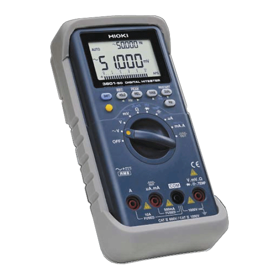
――――――――――――――――――――――――――――――― 第 1 章 各部の名称と機能 ⑬LCD ディスプレイ ②SHIFT/PEAK キー ③HOLD/MAX・MIN キー ④REL キー ⑤RANGE/dBm-Ωキー ⑥DUAL キー ⑦Hz キー ⑧バックライトキー ①ファンクション・ スイッチ ⑫A 端子 ⑪μA.mA. .TEMP. OUT 端子 ⑨V・Ω・ 端子 ⑩COM 端子 ――――――――――――――――――――――――――――――― 第 1 章 各部の名称と機能... - Page 12 ――――――――――――――――――――――――――――――― ①ファンクション・スイッチ(ファンクション・SW) ファンクションの選択、電源の ON/OFF を行います。 ACカップリング電圧 DC,AC,AC+DC電圧 / mV DC,AC,AC+DC電圧(~400 mV) Ω/ 抵抗、コンダクタンス、 (抵抗値による)導通チェック ダイオードチェック、 (電圧による)導通チェック、周波数 コンデンサ容量 / μA DC,AC,AC+DC 400μA,4000μA / mA.A DC,AC,AC+DC 40 mA,400 mA(mA端子使用時), 4 A,10 A(A端子使用時) TEMP/ 温度、パルス出力 ②SHIFT/PEAK キー ACV/dBmを切り換えます。 / mV DC/AC/AC+DCを切り換えます。 Ω/ 抵抗/導通チェック(抵抗値による)を切り換え ます。...
- Page 13 ――――――――――――――――――――――――――――――― ④REL キー ・リラティブ(相対値表示)機能の起動と解除を行います(リラ ティブ機能参照) 。 ⑤RANGE/dBm-Ωキー ・オートレンジ/マニュアルレンジを切り換えます。 ・マニュアルレンジ時のレンジを切り換えます。 ・電圧測定時に dBm 表示が選択されている場合に基準インピー ダンスを切り換えます。 ⑥DUAL キー ・デュアルディスプレイの各種の組み合わせを避択します。組み 合わせは以下の表の通りです。 測定項目 第1ディスプレイ 第2ディスプレイ 備考 Frequency V 時のみ Frequency V, / mV 時のみ Frequency AC+DC V Frequency AC+DC V AC+DC V AC+DC V AC+DC V Frequency Frequency AC+DC A...
- Page 14 ――――――――――――――――――――――――――――――― ⑦Hz キー ・デュアルディスプレイを利用して周波数/デューティ比/パルス 幅測定を切り換えます。デュアルディスプレイの組み合わせは 以下の表の通りです。 測定項目 第1ディスプレイ 第2ディスプレイ Frequency(Hz) Duty Cycle(%) Pulse Width(ms) ACV Frequency(Hz) Duty Cycle(%) Pulse Width(ms) DCV Frequency(Hz) AC+DC V AC+DC V Duty Cycle(%) AC+DC V Pulse Width(ms) AC+DC V Frequency(Hz) Duty Cycle(%) Pulse Width(ms) ACA Frequency(Hz) Duty Cycle(%) Pulse Width(ms) DCA...
- Page 15 ――――――――――――――――――――――――――――――― .TEMP. OUT 端子 ⑪μA.mA. .TEMP.パルス出力ファンクションのときに使用 μA.mA. する端子です。 ⑫A 端子 A ファンクションのときに使用する端子です。 ⑬LCD ディスプレイ バーグラフ スケール表示 21ドットバーグラフ表示(極 性表示付) パワーセーブ機能動作時に点灯 電池が確度保証電圧(約7.2 V)以下になった ときに点滅 DCV,DCmV,DCμA,DCmA,DCA時に点灯 ACV,ACmV,ACμA,ACmA時に点灯 ACDC AC+DC V,AC+DC mV,AC+DC μA,AC+DC mA,AC+DC A時に点灯 AUTO オートレンジ動作時に点灯 △ リラティブ機能動作時に点灯 データホールド機能動作時に点灯 MAX AVG レコーディング機能動作時に点灯 最大読取り値表示時に点灯 平均読取り値表示時に点灯 最小読取り値表示時に点灯...
- Page 16 ――――――――――――――――――――――――――――――― RANGE 8 各ファンクションでの測定レンジ レコーディング機能およびタイマ機能動作時 に点灯 パルス出力時に点灯 通信機能動作時に点灯 TRIG デューティ比およぴパルス幅測定のためのト + リガスロープの極性 - ℃° F 温度測定時の単位 nμF 容量測定時の単位 dBm表示時の単位 ――――――――――――――――――――――――――――――― 第 1 章 各部の名称と機能...
-
Page 17: 第 2 章 測定方法
――――――――――――――――――――――――――――――― 第 2 章 測定方法 感電事故を防ぐため下記のことをお守りください。 警告 ・端子部は、 安全な絶縁距離がとれていません。テスト リードの接続には注意してください。 ・測定端子の差換えをともなうファンクションスイッ チの切換えは、テストリードを被測定物からを外し、 端子から抜いてください。 測定前の準備 テストリードについている保護キャップを外してください。 2.1 電圧測定 ・最大入力電圧は、 DC1200 V、 AC850 Vrms、 または 10 危険 V・Hz です。ただし、 mV ファンクションの最 大入力電圧は、DC600 V、AC600 Vrms、または 10 V・Hz です。最大入力電圧を超えると本器を破損し人 身事故になるので測定しないでください。 ・感電事故を防ぐため、 テストリードの先端で電圧のか かっているラインを短絡しないでください。 注記 トランスや大電流路など強磁界の発生している近く、 ま た無線機など強電界の発生している近くでは、... -
Page 18: ファンクションでの交流電圧測定
――――――――――――――――――――――――――――――― 2.1.1 V ファンクションでの交流電圧測定 (1) ファンクション・SW を V にします。赤のテストリード を V・Ω・ 端子に、黒を COM 端子に接続します。 (2) 被測定回路にテストリードを接続し、表示の値を読みます。 (3) マニュアルレンジ操作の場合、 RANGE/dBm-Ωキーを押し ます (AUTO マークが消えます) 。再びオートレンジにする 場合は、RANGE/dBm-Ωキーを 1 秒以上押します。 (4) SHIFT/PEAK キーを押すと、 dBm 測定機能が起動して dBm 表示に切り換わります。再び V 表示にする場合は、 SHIFT/PEAK キーを押します。 (5) DUAL キーを押すと、デュアルディスプレイモードが設定 されます。DUAL キーを押すごとに以下のように表示が切... - Page 19 ――――――――――――――――――――――――――――――― ・dBm 表示時に、 RANGE/dBm-Ωキーを押して基準イ 注記 ンピーダンスを切り換えることができます。キーを 押すごとにインピーダンスが変化していきますので、 希望の値を表示させ、 約 4 秒間そのままにしてくださ い。設定したインピーダンスで測定が再開されます。 ・設定可能な基準インピーダンスは、4, 8, 16, 32, 50, 75, 93, 110, 125, 135, 150, 200, 250, 300, 500, 600, 800, 900, 1000, 1200Ωの 20 種類です。 ・デフォルトの基準インピーダンスは、600 Ωです。 (本体の電源を切るとこの設定に戻ります。 ) ・デューティ比およびパルス幅測定時に SHIFT/PEAK キーを...
-
Page 20: V, / Mv ファンクションでの電圧測定
――――――――――――――――――――――――――――――― 2.1.2 mV ファンクションでの電圧測定 V ま (1) ファンクション・SW を測定する電圧に応じて mV にします。赤のテストリードを V・Ω・ たは 端子に、黒を COM 端子に接続します。 (2) 被測定回路にテストリードを接続し、表示の値を読みます。 (3) マニュアルレンジ操作の場合、 RANGE/dBm-Ωキーを押し ます (AUTO マークが消えます) 。再びオートレンジにする 場合は、RANGE/dBm-Ωキーを 1 秒以上押します。 (4) SHIFT/PEAK キーを押すと、DCV(mV)/ACV(mV)/ (AC+DC)V(mV)測定に順番に切り換わります。 (5) DUAL キーを押すと、デュアルディスプレイモードが設定 されます。DUAL キーを押すごとに以下のように表示が切 り換わります。 ・DCV(mV)測定時 第 1 ディスプレイ 第 2 ディスプレイ DCV(mV) Hz ↓ ... - Page 21 ――――――――――――――――――――――――――――――― ・(AC+DC)V(mV)測定時 第 1 ディスプレイ 第 2 ディスプレイ (AC+DC)V(mV) ↓ ↓ dBm (AC+DC)V(mV) ↓ ↓ (AC+DC)V(mV) ACV(mV) ↓ ↓ DCV(mV) (AC+DC)V(mV) ↓ ↓ (AC+DC)V(mV) 表示なし (6) Hz キーを押すと、 デュアルディスプレイモードによる周波 数(デューティ比、パルス幅)測定機能が設定されます。 Hz キーを押すごとに以下のように表示が切り換わります。 デュアルディスプレイモードを解除する場合は Hz キーを 1 秒以上押します。 第 1 ディスプレイ 第 2 ディスプレイ Hz ...
- Page 22 ――――――――――――――――――――――――――――――― 0~750 VAC,1000 VDC 赤 黒 0~400 mVAC/DC 赤 黒 ――――――――――――――――――――――――――――――― 第 2 章 測定方法...
-
Page 23: 抵抗およびコンダクタンス(1/Ω)測定
――――――――――――――――――――――――――――――― 2.2 抵抗およびコンダクタンス (1/Ω) 測定 ・抵抗測定のファンクションに電圧を入力しないでく 危険 ださい。本器を破損し、人身事故になります。 電気事故を防ぐため、測定回路の電源を切ってから、 測定してください。 2.2.1 抵抗測定 (1) ファンクション・SW を Ωにします。 (2) 赤のテストリードを V・Ω・ 端子に、 黒を COM 端子に接 続します。 (3) 被測定回路にテストリードを接続し、表示の値を読みます。 (4) マニュアルレンジ操作の場合、 RANGE/dBm-Ωキーを押し ます (AUTO マークが消えます) 。再びオートレンジにする 場合は、RANGE/dBm-Ωキーを 1 秒以上押します。 (5) SHIFT/PEAK キーを押すごとに導通チェック機能の起動/ 解除を行います( マークが点灯/消灯します) 。この時、 オートレンジは解除されます。... - Page 24 ――――――――――――――――――――――――――――――― PUSH PUSH 0~40 MΩ 赤 黒 ――――――――――――――――――――――――――――――― 第 2 章 測定方法...
-
Page 25: コンダクタンス(1/Ω)測定
――――――――――――――――――――――――――――――― 2.2.2 コンダクタンス(1/Ω)測定 (1) ファンクション・SW を Ωにします。 (2) 赤のテストリードを V・Ω・ 端子に、 黒を COM 端子に接 続します。 (3) LCD ディスプレイに"OL"が表示されるまでテストリード を開放しておきます。 (4) RANGE/dBm-Ωキーを 2 回押し、レンジ 7 にします。 (5) REL キーを押して、表示値をゼロにします。 (6) 被測定回路にテストリードを接続し、表示の値を読みます。 ・コンダクタンス測定時の表示単位は nS(ナノ・ジー 注記 メンス)です。 25 MΩ~∞ 赤 黒 ――――――――――――――――――――――――――――――― 第 2 章 測定方法... -
Page 26: ダイオードチェック
――――――――――――――――――――――――――――――― 2.3 ダイオードチェック ・ダイオードチェックのファンクションに電圧を入力 危険 しないでください。本器を破損し、 人身事故になりま す。 電気事故を防ぐため、測定回路の電源を切ってから、 測定してください。 (1) ファンクション・SW を Hz にします。 (2) 赤のテストリードを V・Ω・ 端子に、 黒を COM 端子に接 続します。 (3) 被測定回路にテストリードを接続します。 (4) 正常なシリコンダイオードでは、順方向電圧 0.4 V~0.7 V を表示します。逆方向では、"OL"を表示します。ダイオー ドが短絡している場合は 0V 付近を(ブザーが鳴ります) 、 断線している場合は順方向で"OL"を表示します。 (5) 測定電圧が約 0.1 V 以下のとき、 ブザーが鳴ります (電圧に よる導通チェック)... -
Page 27: 周波数測定
――――――――――――――――――――――――――――――― 2.4 周波数測定 ・最大入力電圧は DC1200 V、AC850 Vrms または 10 危険 V・Hz です。最大入力電圧を超えると本器を破損し人 身事故になるので測定しないでください。 (1) ファンクション・SW を Hz にし、 SHIFT/PEAK キー を押します。 (2) 赤のテストリードを V・Ω・ 端子に、 黒を COM 端子に接 続します。 (3) 被測定回路にテストリードを接続し、表示の値を読みます。 (4) DUAL キーを押すごとに周波数測定範囲が切り換わります (第 2 ディスプレイの表示が"-1-"/"-100-"と切り換わりま す) 。 (5) Hz キーを押すと、周波数/デューティ比/パルス幅測定に順 番に切り換わります。... - Page 28 ――――――――――――――――――――――――――――――― PUSH 1~10 MHz PUSH PUSH PUSH PUSH 赤 黒 PUSH PUSH ――――――――――――――――――――――――――――――― 第 2 章 測定方法...
-
Page 29: コンデンサ容量測定
――――――――――――――――――――――――――――――― 2.5 コンデンサ容量測定 .TEMP. OUT 端子に電圧を入力し ・μA.mA. 危険 ないでください。本器を破損し、人身事故になりま す。 ・チャージされていると思われるコンデンサは、 両端を 警告 短絡させ放電してから測定してください。本器を破 損し、人身事故になります。 (1) ファンクション・SW を にします。 (2) 赤のテストリードをμA.mA. .TEMP. OUT 端子 に、黒を COM 端子に接続します。 (3) テストリードを開放し、 REL キーを押して表示値をゼロに します。 (4) 被測定回路にテストリードを接続し、表示の値を読みます。 ・極性のあるコンデンサを測定する場合には極性を守 注記 ってください。 ・測定の前にコンデンサを放電してください。 ・低容量のコンデンサを測定する場合、 付属のテストリ ードを使用すると、 テストリードの構造上人体からの ノイズの影響で、... - Page 30 ――――――――――――――――――――――――――――――― 0~9999μF 黒 赤 ――――――――――――――――――――――――――――――― 第 2 章 測定方法...
-
Page 31: 電流測定
――――――――――――――――――――――――――――――― 2.6 電流測定 ・600 V 以上の電位の場合、 回路内の電流測定は行わな 警告 いでください。電流ファンクションの過負荷保護は AC600 V です。 ・電気事故を防ぐため、 測定回路の電源を一度切ってか ら、テストリードを接続し、測定してください。 ・電流レンジに電圧を入力しないでください。本器を 破損し、人身事故になります。 2.6.1 μA 測定(400μA, 4000μA) (1) ファンクション・SW を / μA にします。 (2) 赤のテストリードをμA.mA. .TEMP. OUT 端子 に、黒を COM 端子に接続します。 (3) SHIFT/PEAK キーを押して DC/AC/(AC+DC)を選択しま す。 (4) 被測定回路にテストリードを接続し、表示の値を読みます。 (5) マニュアルレンジ操作の場合、... - Page 32 ――――――――――――――――――――――――――――――― ・ACμA 測定時 第 1 ディスプレイ 第 2 ディスプレイ ACμA Hz ↓ ↓ DCμA ACμA ↓ ↓ ACμA 表示なし ・(AC+DC)μA 測定時 第 1 ディスプレイ 第 2 ディスプレイ (AC+DC)μA Hz ↓ ↓ ACμA (AC+DC)μA ↓ ↓ DCμA (AC+DC)μA ↓ ↓ (AC+DC)μA 表示なし (7) Hz キーを押すと、 デュアルディスプレイモードによる周波 数(デューティ比、パルス幅)測定機能が設定されます。...
- Page 33 ――――――――――――――――――――――――――――――― 0~4 mA DC/AC 黒 赤 ――――――――――――――――――――――――――――――― 第 2 章 測定方法...
-
Page 34: Ma 測定(40 Ma, 400 Ma
――――――――――――――――――――――――――――――― 2.6.2 mA 測定(40 mA, 400 mA) (1) ファンクション・SW を / mA.A にします。 (2) 赤のテストリードをμA.mA. .TEMP. OUT 端子 に、黒を COM 端子に接続します。 (3) SHIFT/PEAK キーを押して DC/AC/(AC+DC)を選択しま す。 (4) 被測定回路にテストリードを接続し、表示の値を読みます。 (5) マニュアルレンジ操作の場合、 RANGE/dBm-Ωキーを押し ます (AUTO マークが消えます) 。再びオートレンジにする 場合は、RANGE/dBm-Ωキーを 1 秒以上押します。 (6) DUAL キーを押すと、デュアルディスプレイモードが設定 されます。DUAL キーを押すごとに以下のように表示が切... - Page 35 ――――――――――――――――――――――――――――――― (7) Hz キーを押すと、 デュアルディスプレイモードによる周波 数(デューティ比、パルス幅)測定機能が設定されます。 Hz キーを押すごとに以下のように表示が切り換わります。 デュアルディスプレイモードを解除する場合は Hz キーを 1 秒以上押します。 第 1 ディスプレイ 第 2 ディスプレイ Hz DCmA/ACmA/(AC+DC)mA ↓ ↓ %(デューティ比) DCmA/ACmA/(AC+DC)mA ↓ ↓ ms(パルス幅) DCmA/ACmA/(AC+DC)mA 周波数およびパルス幅測定時には RANGE/dBm-Ωキーによる オートレンジ/マニュアルレンジ切換えが可能です。 ・デューティ比およびパルス幅測定時に SHIFT/PEAK 注記 キーを 1 秒以上押すと、 トリガスロープが+または- に切り換わります (バーグラフの極性表示が切り換わ ります) 。 0~400 mA DC/AC 黒...
-
Page 36: A 測定(10 A
――――――――――――――――――――――――――――――― 2.6.3 A 測定(10 A) ・10A レンジの最大入力電流は DC10 A/ AC10 A rms で 警告 す。 この電流を超えると本器を破損し、 人身事故 にな るので入力しないでください。 (1) ファンクション・SW を / mA.A にします。 (2) 赤のテストリードを A 端子に、黒を COM 端子に接続しま す。 (3) SHIFT/PEAK キーを押して DC/AC/(AC+DC)を選択しま す。 (4) 被測定回路にテストリードを接続し、表示の値を読みます。 (5) DUAL キーを押すと、デュアルディスプレイモードが設定 されます。DUAL キーを押すごとに以下のように表示が切... - Page 37 ――――――――――――――――――――――――――――――― (6) Hz キーを押すと、 デュアルディスプレイモードによる周波 数(デューティ比、パルス幅)測定機能が設定されます。 Hz キーを押すごとに以下のように表示が切り換わります。 デュアルディスプレイモードを解除する場合は Hz キーを 1 秒以上押します。 第 1 ディスプレイ 第 2 ディスプレイ Hz DCA/ACA/(AC+DC)A ↓ ↓ %(デューティ比) DCA/ACA/(AC+DC)A ↓ ↓ ms(パルス幅) DCA/ACA/(AC+DC)A 周波数およびパルス幅測定時には RANGE/dBm-Ωキーによる オートレンジ/マニュアルレンジ切換えが可能です。 ・デューティ比およびパルス幅測定時に SHIFT/PEAK 注記 キーを 1 秒以上押すと、 トリガスロープが+または- に切り換わります (バーグラフの極性表示が切り換わ ります) 。 0~10 A DC/AC 黒...
-
Page 38: 温度測定
――――――――――――――――――――――――――――――― 2.7 温度測定 .TEMP. OUT 端子に電圧を入力し ・μA.mA. 危険 ないでください。本器を破損し、人身事故になりま す。 (1) ファンクション・SW を TEMP/ にします。 (2) オプ シ ョン の 温度 プロー ブ(9180,9181,9182,9183)を .TEMP. OUT 端子 (+側端子) と COM 端 μA.mA. 子(-側端子)に接続します。 (3) 温度を測定したい熱源にプローブをあて、表示の値を読み ます。 (4) DUAL キーを押すと、℃(摂氏)/° F ( 華氏)の表示が第 1 デ ィスプレイと第... - Page 39 ――――――――――――――――――――――――――――――― PUSH ――――――――――――――――――――――――――――――― 第 2 章 測定方法...
-
Page 40: パルス出力
――――――――――――――――――――――――――――――― 2.8 パルス出力 .TEMP. OUT 端子に電圧を入力し ・μA.mA. 危険 ないでください。本器を破損し、人身事故になりま す。 (1) ファンクション・SW を TEMP/ にします。 (2) SHIFT/PEAK キーを押して、パルス出力機能を起動します マークが点滅します) 。再度 SHIFT/PEAK キーを押す ( と機能が解除され、温度測定ファンクションに設定されま す。 (3) Hz キーを押して、 出力信号の周波数 (16 種類) を選択しま す。キーを押し続けると周波数が連続して変化します。 (4) DUAL キーを押して、 出力周波数のデューティ比 (1~99%) を選択します。キーを押し続けるとデューティ比が連続し て変化します。 ・パルス出力機能を選択した時点でパルス電圧が出力 注記... - Page 41 ――――――――――――――――――――――――――――――― 試験回路 レベル 変換器 ――――――――――――――――――――――――――――――― 第 2 章 測定方法...
-
Page 42: タイマ+信号出力機能
――――――――――――――――――――――――――――――― 2.9 タイマ+信号出力機能 .TEMP. OUT 端子に電圧を入力し ・μA.mA. 危険 ないでください。本器を破損し、人身事故になりま す。 (1) ファンクション・SW を TEMP/ にします。 (2) SHIFT/PEAK キーを 1 秒間押し続け、 タイマ機能を起動し ます。第 2 ディスプレイには"Lo-Hi"(Low to High)が表 示されます。 再度 SHIFT/PEAK キーを 1 秒以上押し続ける と機能が解除され、温度測定ファンクションに設定されま す。 (3) DUAL キーを押して、信号出力の状態を"Lo-Hi"、"Hi-Lo" (High to Low) 、 "Hi-PS" ( Pulse of Low to High) 、 "Lo-PS" (Pulse of High to Low)の... - Page 43 ――――――――――――――――――――――――――――――― PUSH コントロール ユニット ――――――――――――――――――――――――――――――― 第 2 章 測定方法...
- Page 44 ――――――――――――――――――――――――――――――― ――――――――――――――――――――――――――――――― 第 2 章 測定方法...
-
Page 45: 第 3 章 応用測定
――――――――――――――――――――――――――――――― 第 3 章 応用測定 本器では次に挙げるような各種の機能が用意されています。 ・レコーディング機能 ・データホールド/リフレッシュホールド機能 ・リラティブ(相対値表示)機能 ・バーグラフ ・パワーセーブ機能 (オートパワーオフ機能およびスリープ機能) ・表示カウント切換え機能 ・LCD ディスプレイ表示確認機能 ・バックライト機能 ・抵抗測定による導通チェック機能 ・デュアルディスプレイ機能 ・1 ms ピークホールド機能 ・RS-232C データ通信機能 ・電流入力端子誤挿入警告機能 ・パワーオンオプション 3.1 レコーディング機能 レコーディング機能は測定中の最大値 (MAX) 、 最小値 (MIN) 、 平均値(AVG)を自動的にメモリに記録する機能です。 (1) HOLD/MAX・MIN キーを 1 秒以上押し続けると、レコーデ ィング機能が起動します。"MAX AVG MIN"マークが点灯 します。... - Page 46 ――――――――――――――――――――――――――――――― (4) 過負荷が記録されると、平均値の算出は停止します。この 場合、平均値は"OL"(過負荷)となります。 (5) 第 2 ディスプレイは MAX または MIN 表示しているときに はその値を記録した時間を、その他のときはレコーディン グ機能が起動してからの経過時問を表示します。 ・レコーディング機能の実行時にはパワーセーブ機能 注記 は解除され、 マークは消灯します。 ・レコーディング機能の記録速度は約 10 回/秒です。 ・平均値は、 レコーディング機能が起動してから記録さ れたすべての測定値の平均値です。 ・経過時間の単位は秒で、最大表示時間は 99,999 秒で す。 PUSH 1 秒 PUSH PUSH PUSH 1 秒 PUSH PUSH 1 秒 PUSH PUSH 1 秒...
-
Page 47: データホールド/リフレッシュホールド機能
――――――――――――――――――――――――――――――― 3.2 データホールド/リフレッシュホール ド機能 3.2.1 データホールド機能 HOLD/MAX・MIN キーを押すと、データホールド機能が起動し、 DH マークが点灯します。表示された測定値が固定されます。 再度 HOLD/MAX・MIN キーを押すと解除され、 DH マークは消灯 します。 ・バーグラフはホールドされず、 現在の測定値を表示し 注記 ます。 3.2.2 リフレッシュホールド機能 リフレッシュホールド機能は測定値が変化した場合に表示値を 固定する機能です。パワーオンオプションにより、データホー ルド機能をリフレッシュホールド機能に切り換えます。 (1) リ フ レ ッ シ ュ ホ ー ル ド 機 能 を 選 択 す る 場 合 は、 HOLD/MAX・MIN キーを押しながら電源を投入します。電... -
Page 48: リラティブ(相対値表示)機能
――――――――――――――――――――――――――――――― 3.3 リラティブ(相対値表示)機能 リラティブ機能はパルス出力ファンクションを除く全ての測定 ファンクションで動作し、測定データからデータ補正値(基準 値)をマイナスする演算処理を行い、演算結果を表示する機能 です。オートレンジ動作およびマニュアルレンジ動作における どのレンジでもリラティブ機能を設定できます。 REL キーを押すと、 Δマークが点灯します。 再度 REL キーを押 すと解除されΔマークは消灯します。 リラティブ機能が起動した時点で以下の動作を行います。 (1) 表示されているデータを基準値としてセットします。 (2) バーグラフのゼロ位置がグラフの中央に設定されます。 (3) 測定データが過負荷の場合は極性を含めた過負荷表示 ("OL"表示)を行います。 ・過負荷時 ("OL"表示時) にはリラティブ機能は起動し 注記 ません。 ・ リ ラ テ ィ ブ 機 能 は、 フ ァ ン ク シ ョ ン の 切 換 え、 SHIFT/PEAK キー、RANGE/dBm-Ωキー、DUAL キ... -
Page 49: パワーセーブ機能 (オートパワーオフ機能およびスリープ機能
――――――――――――――――――――――――――――――― 3.5 パワーセーブ機能(オートパワーオフ 機能およびスリープ機能) 本体の無駄な電池消耗を防ぐために、本器には 2 段階のパワー セーブ機能が備わっています。この機能は電源を入れると自動 的に起動します( マーク点灯) 。以下の動作を行います。 (1) 最終操作をしてから約 15 分間、 次のいずれかの動作がない と、スリープ機能によりスリープモードに入ります。 ・キースイッチの操作 ・測定ファンクションの変更 ・レコーディング機能の設定 ・1ms ピークホールド機能の設定 (2) スリープモードでは、LCD ディスプレイに" "が点滅し ます。スリープモードから復帰させたい場合には、いずれ かのキーを 0.5 秒以上押し続けるか、 ファンクション・SW を操作してください。 (3) スリープモードを解除せずに 15 分間経過すると、 オートパ ワーオフ機能により自動的に本体の電源が切れます。 (4) オートパワーオフ機能により電源が切れた後に本体の電源 を入れるには、 ファンクション・SW を OFF 位置に合わせ てから電源を入れ直してください。... -
Page 50: 表示カウント切換え機能
――――――――――――――――――――――――――――――― 3.6 表示カウント切換え機能 4000 カウント表示と 40000 カウント表示とを切り換えること ができます。切換え方法は以下の 2 つの方法があります。 (1) 本体の電源を投入した状態で、バックライトキーを 1 秒以 上押し続けます。再度バックライトキーを 1 秒以上押し続 けると、切換え前のカウント表示に戻ります。 (2) RANGE/dBm-Ωキーを押しながら本体の電源を投入しま す (パワーオンオプション) 。40000 カウント表示が選択さ れます。 注記 ・デュアルディスプレイ機能を起動している場合には 第 1 ディスプレイ、 第 2 ディスプレイともに表示カウ ントが切り換わります。 ・通常の電源投入時 (パワーオンオプション機能を利用 しない場合)には 4000 カウント表示が自動的に選択 されます。 ・容量測定ファンクションでは表示カウント切換えは 行われません(4000 カウント表示固定)... -
Page 51: バックライト機能
――――――――――――――――――――――――――――――― 3.8 バックライト機能 バックライトキーを押すと、 LCD ディスプレイのバックライト の点灯/消灯が交互に切換わります。バックライトは点灯後、 30 秒経過すると自動的に消灯します(バックライト自動消灯機 能) 。 ●バックライト自動消灯機能の解除 バックライトを連続して点灯させたい場合にはバックライト自 動消灯機能(30 秒後に自動消灯)を解除する必要があります。 パワーオンオプションにより、この機能を解除することができ ます。機能を解除する場合は、バックライトキーを押しながら 電源を投入し、 LCD ディスプレイに表示マークが全て表示され たら、キーから指を離します。電源を切るまでは、バックライ ト自動消灯機能は解除された状態となります。 3.9 抵抗測定による導通チェック機能 Ωファンクションでは、SHIFT/PEAK キーを押すと抵抗測定に よる導通チェック機能が起動します。 再度 SHIFT/PEAK キーを 押すと解除されます。 導通チェック機能が起動した時点で以下の動作を行います。 (1) 測定レンジを 400Ωレンジに切り換えます。オートレンジ 動作の場合は、マニュアルレンジ動作になります。 (2) 各レンジの 100 カウント (40000 カウント表示時は 1000 カ ウント)以下の抵抗値の場合にブザーが鳴ります。... -
Page 52: デュアルディスプレイ機能
――――――――――――――――――――――――――――――― 3.10 デュアルディスプレイ機能 デュアルディスプレイ機能は、 1 つの信号に対して 2 種類の異な る測定パラメータ(電圧、電流、周波数、デューティ比、パル ス幅など)を同時にモニタする機能です。 DUAL キーまたは Hz キーを押すことによりデュアルディスプ レイ機能が起動し、第 1 ディスプレイと第 2 ディスプレイにそ れぞれ異なる測定パラメータが表示されます。機能を解除する には機能を起動した DUAL キーまたは Hz キーを 1 秒以上押し 続けてください。測定パラメータの組み合わせについては第2 章の各測定ファンクションの説明を参照してください。 3.11 1 ms ピークホールド機能 1 ms ピークホールド機能は電圧、 電流測定ファンクションで動 作し、入力信号波形のピーク値を観測する機能です。例えば、 この機能を利用して波高率(クレストファクタ)を決定するこ とができます。 波高率(クレストファクタ)=波形のピーク値/真の rms 値 SHIFT/PEAK キーを... - Page 53 ――――――――――――――――――――――――――――――― (4) 測定データがオーバーレンジ("OL"が表示されます)の場 合は、 RANGE/dBm-Ωキーを押して、 測定レンジを変更し てください。測定が最初からスタートします。 (5) DUAL キーを押すと、ホールドされたデータがリセットさ れて 1 ms ピークホールド動作を最初からスタートします (最大値または最小値の表示モードは変化しません) 。 ・1 ms ピークホールド機能は、DC カップリング状態 注記 ("DC"が点灯した状態) でのみ確度を規定します (4.2 確度表参照) 。 ・1 ms ピークホールド機能を解除するとオートレンジ 動作になります。 ――――――――――――――――――――――――――――――― 第 3 章 応用測定...
-
Page 54: Rs-232C データ通信機能
――――――――――――――――――――――――――――――― 3.12 RS-232C データ通信機能 本器は RS-232C インタフェースを利用したデータの送信機能 を装備しています。この機能によって、パソコンと本器を接続 して測定データの転送を行い、パソコンにて記録および保存す ることができます。 この機能を利用するには、専用の通信ケープルとソフトウェア がセットになった別売のオプション(3852 RS-232C パッケー ジ)が必要です。パソコンにデータ転送を行う場合には次の手 順にしたがってください。 (1) DUAL キーを押しながら電源を投入し、そのままの状態で 1 秒間 DUAL キーを押し続け、DUAL キーから手を離しま す。 マークが点灯します。 (2) 通信ケーブルの光コネクタ側を本器のホルスタに接続しま す。この時、 "RS-232C lNTERFACE"の文字が上になるよ うに接続してください。ケーブルの他方の D‐sub9pin コ ネクタをパソコンの RS-232C インタフェースに接続しま す。 (3) ソフトウェアを実行し、データを取り出します。 ・ソフトウェアの使用方法は 3852 RS-232C パッケー 注記... -
Page 55: 電流入力端子誤挿入警告機能
――――――――――――――――――――――――――――――― 3.13 電流入力端子誤挿入警告機能 本器には、電圧測定時などの短絡事故防止のため、未然に誤操 作を防ぐ機能があります。以下の条件で警告状態になり、第 1 ディスプレイに " Error " 表示が点滅し、ブザーが鳴ります。 ・ファンクション・SW が / mA.A 以外の位置で A 端子にテス トリードが差し込まれた場合 ・A 端子のヒューズが断線している場合は、 本機能は動 注記 作しません。 ――――――――――――――――――――――――――――――― 第 3 章 応用測定... -
Page 56: パワーオンオプション
――――――――――――――――――――――――――――――― 3.14 パワーオンオプション パワーオンオプションはあるキーを押しながら電源を投入する ことで本体の機能を選択する動作を示しています。選択した機 能は本体の電源を切るまで有効です。以下に各キーに割り当て られたパワーオンオプションの機能を示します。 ●SHIFT/PEAK キー ・LCD ディスプレイ表示の確認機能を起動します。 LCD ディスプレイの表示を確認するために使用します。表示 が全て点灯した状態でどれかのキーを押すと確認は終了します。 ・パワーセーブ機能を解除します( マークが消灯します) 。 ●HOLD/MAX・MIN キー ・リフレッシュホールド機能を有効にします。 ●REL キー ・タイマ+信号出力機能以外の本体動作時のブザー音を鳴らない ようにします。ダイオードチェック時、導通チェック時にもブ ザーは鳴りません。 ●RANGE/dBm-Ωキー ・40000 カウント表示を選択します。 ●バックライトキー ・バックライト自動消灯機能を無効にします。 ●DUAL キー ・RS-232C インタフェースを利用したデータ送信機能を有効に します( マークが点灯します) 。 ――――――――――――――――――――――――――――――― 第 3 章 応用測定... -
Page 57: 第 4 章 仕様
――――――――――――――――――――――――――――――― 第 4 章 仕様 4.1 一般仕様 測定方式 二重積分方式 交流測定方式 真の実効値測定方式 表示方式 液晶表示体、バックライト付き 最大測定カウント 40000カウント、4000カウント 極性表示 "-"マークのみ自動点灯 電池消耗表示 マーク点滅 レンジ切換え フルオートレンジおよびマニュアルレンジ ファンクションスイッチ ロータリスイッチ サンプリングレート 約3回/秒(Ω,Hz以外,4000カウント表示時) 約0.8回/秒(Ω,Hz以外,40000カウント表示時) 約0.8回/秒 (Ω,Hz) 0.25~4回/秒 (デューティ比、パルス幅) 約20回/秒(バーグラフ) 使用場所 屋内、高度2000 mまで 使用温湿度範囲 0~50℃、80%rh以下(結露なし) 保存温湿度範囲 -20℃~60℃、80%rh以下(結露なし) 温度特性 23℃±5℃以外、(測定確度)×0.15/℃ 電源 積層形乾電池(6F22)×1 定格電源電圧... - Page 58 ――――――――――――――――――――――――――――――― 最大入力電圧 DCV,ACV,(AC+DC)V: 40 mV~400 mVレンジ:DC600 V/AC600 Vrms その他のレンジ:DC1200 V/AC850 Vrms DCA,ACA,(AC+DC)A: 400μA~400 mAレンジ:ヒューズ保護 1 A/AC600 V 4 A~10 Aレンジ:ヒューズ保護 15 A/AC600 V Ω,C,ダイオード/ 導通チェック:DC600 V/AC600 Vrms Hz:DC1200 V/AC850 Vrmsまたは10 V・Hz TEMP:DC600 V/AC600 Vrms 耐電圧 ケース-入力端子間 AC6 kVrms sin (50/60 Hz 1分間) ノイズ除去...
-
Page 59: 確度表
――――――――――――――――――――――――――――――― 4.2 確度表 弊社では測定値の限界誤差を、次に示す rdg.(リーディング) 、 dgt.(デジット)に対する値として定義しています。 ・rdg.(読み値、表示値、指示値) 現在測定中の値、測定器が現在指示している値を表します。 ・dgt.(分解能) ディジタル測定器における最小表示単位、 つまり最小桁の"1"を 表します。 確度保証条件 ・23℃±5℃、80%rh 以下 ただし結露なきこと 確度保証期間 ・確度保証条件にて1年間保証 ・測定確度は 4000 カウント表示モードで規定する。 注記 (40000 カウントモードでの測定確度は表中の数値に ついて rdg.誤差はそのままに dgt.誤差を 10 倍したも のとする) ●DCV ファンクション 過負荷 分解能 レンジ 測定確度 保護 (40000カウント時) 40mV 10μV(1μV) ±0.08%rdg.±5dgt. 600V DC/ AC rms 400mV 0.1mV(10μV) - Page 60 ――――――――――――――――――――――――――――――― ●ACV ファンクション 測定確度 過負荷 分解能 レンジ 保護 (40000カウント時) 50/60Hz 45Hz~5kHz 5kHz~20kHz 600V DC/ 40mV 10μV(1μV) ±0.7%rdg.±5dgt.±1.5%rdg.±5dgt. ±2%rdg.±5dgt. AC rms 400mV 0.1mV(10μV) ±0.7%rdg.±5dgt.±1.5%rdg.±5dgt. ±2%rdg.±5dgt. V・Hz 1mV(0.1mV) ±0.7%rdg.±5dgt.±1.5%rdg.±5dgt. ±2%rdg.±5dgt. 1200V DC/ 10mV(1mV) ±0.7%rdg.±5dgt.±1.5%rdg.±5dgt. ±2%rdg.±5dgt. 850V AC rms 400V 0.1V(10mV) ±0.7%rdg.±5dgt.±1.5%rdg.±5dgt. ±2%rdg.±5dgt. V・Hz 750V 1V(0.1V)
- Page 61 ――――――――――――――――――――――――――――――― ●ACA ファンクション 測定確度 過負荷 分解能 レンジ 内部抵抗 (45 Hz~2 kHz) 保護 (40000カウント時) 400μA 0.1μA(10nA) ±1.0%rdg.±5dgt. 約100Ω 4000μA 1μA(0.1μA) ±1.0%rdg.±5dgt. 約100Ω 1A/AC600V, High Energy 40mA 10μA(1μA) ±1.0%rdg.±5dgt. 約1Ω Fuse 400mA 0.1mA(10μA) ±1.0%rdg.±5dgt. 約1Ω 1mA(0.1mA) ±1.0%rdg.±5dgt. 約0.01Ω 15A/AC600V, High Energy 10mA(1mA) ±1.0%rdg.±5dgt.
- Page 62 ――――――――――――――――――――――――――――――― ●1ms ピークホールドモード ・測定確度は、 DC カップリング状態において、 ±40dgt. 注記 (40000 カウント表示モードでは±400dgt.)以上で 1ms を超える変化時間を持つ信号に対して規定して います。 ・DC カップリング状態:"DC"が点灯した状態 V ファンクション(DC カップリング時) 過負荷 分解能 レンジ 測定確度 保護 (40000カウント時) 600V DC/ 40mV 10μV(1μV) ±2%rdg.±43dgt. AC rms 400mV 0.1mV(10μV) ±2%rdg.±43dgt. V・Hz 1mV(0.1mV) ±2%rdg.±43dgt. 1200V DC/ 10mV(1mV) ±2%rdg.±43dgt.
- Page 63 ――――――――――――――――――――――――――――――― ●Ωファンクション 過負荷 分解能 レンジ 測定確度 開放端子電圧 保護 (40000カウント時) 400Ω 0.1Ω(0.01Ω) ±0.2%rdg.±3dgt. 3.3V(Max.) 4kΩ 1Ω(0.1Ω) ±0.2%rdg.±3dgt. 1.28V(Max.) 40kΩ 10Ω(1Ω) ±0.2%rdg.±3dgt. 1.28V(Max.) 600V DC/AC 400kΩ 100Ω(10Ω) ±0.2%rdg.±3dgt. 1.28V(Max.) 4MΩ 1kΩ(0.1kΩ) ±0.2%rdg.±3dgt. 1.28V(Max.) 40MΩ 10kΩ(1kΩ) ±1%rdg.±5dgt. 1.28V(Max.) 40nS 0.01nS(0.001nS) ±1%rdg.±10dgt. 1.28V(Max.) ・ 導 通 チ ェ ッ ク 機 能 動 作 時 に は 抵 抗 値 が 各 レ ン ジ の 100dgt.(40000 カウント表示モードでは...
- Page 64 ――――――――――――――――――――――――――――――― ●V ファンクションでの Hz 測定モード 最小入力 過負荷 分解能 レンジ 測定確度 周波数 保護 (40000カウント時) 100Hz 0.01Hz(0.001Hz) ±0.02%rdg.±1dgt. 10Hz 1.600V DC/AC rms 1kHz 0.1Hz(0.01Hz) ±0.02%rdg.±1dgt. 10Hz (mVレンジ) 10kHz 1Hz(0.1Hz) ±0.02%rdg.±1dgt. 10Hz 2.1200V DC/ 850V AC rms 100kHz 10Hz(1Hz) ±0.02%rdg.±1dgt. 10Hz (Vレンジ) 200kHz 100Hz(10Hz) ±0.02%rdg.±1dgt.
- Page 65 ――――――――――――――――――――――――――――――― ●Hz ファンクション (Divide 1 モード:第 2 ディスプレイの表示が"-1-"の場合) 分解能 最小入力 過負荷 レンジ 測定確度 感度 (40000カウント時) 周波数 保護 100Hz 0.01Hz(0.001Hz) ±0.002%rdg.±1dgt. 100mV rms 1200V DC/ 1kHz 0.1Hz(0.01Hz) ±0.002%rdg.±1dgt. 100mV rms 850V AC rms 10kHz 1Hz(0.1Hz) ±0.002%rdg.±1dgt. 100mV rms 100kHz 10Hz(1Hz) ±0.002%rdg.±1dgt. 100mV rms V・Hz 200kHz 100Hz(10Hz)
- Page 66 ――――――――――――――――――――――――――――――― ●パルス出力ファンクション ・周波数:0.5Hz, 1Hz, 2Hz, 10Hz, 50Hz, 60Hz, 75Hz, 100Hz, 150Hz, 200Hz, 300Hz, 600Hz, 1200Hz, 1600Hz, 2400Hz, 4800Hz ・デューティ比可変範囲:1%~99% ・確度:±1.0% ・振幅(固定):+3V±0.2V ・出力インピーダンス:3.5kΩ(Max.) ●タイマ出力ファンクション ・タイマ設定時間(最大):99,999 秒 ・振幅(固定):+3V±0.2V ・出力インピーダンス:3.5kΩ(Max.) ・出力信号:1. High → Low Level (3V → 0V) 2. Low パルス出力 (パルス幅:0.8ms~6.67ms) 3. Low → High Level (0V → 3V) 4.
-
Page 67: 第 5 章 保守・サービス
――――――――――――――――――――――――――――――― 第 5 章 保守・サービス 5.1 電池およびヒューズの交換方法 ・電池、 ヒューズの交換時には、 感電事故を避けるため、 警告 テストリードを被測定物より外してから行ってくだ さい。また、交換後は必ずふた(ケース)をして、ね じ止め後使用してください。 ・電池を交換するときは、極性+-に注意し、逆挿入し ないでください。性能劣化や液漏れの原因になりま す。 ・使用済の電池をショート、分解、火の中に投入しない でください。破裂する恐れがあり、危険です。 ・使用済の電池は地域で定められた規則に従って処分 してください。 ・ヒューズ交換は、指定された形状と定格電流、電圧の ものを使用してください。指定以外のヒューズを用 いたりヒューズホルダを短絡すると、 人身事故になる ので注意してください。 μA.mA および A 端子には、回路保護の目的でヒューズが入っ ています。電流測定ができないときは、過電流によるヒューズ の断線が考えられます。 図を参照し、以下の手順で交換してください。 ――――――――――――――――――――――――――――――― 第 5 章 保守・サービス... -
Page 68: 電池交換
――――――――――――――――――――――――――――――― 5.1.1 電池交換 積層形乾電池 (6F22) ×1 個 (1) テストリードを測定回路から外し、 ファンクションスイッ チが OFF になっていることを確認します。 (2) ホルスタを外します。 (3) 下ケース(本体底面)を上にし、プラスドライバーを使用 してケース止めネジを 3 本外します。 (4) 下ケースを持ち上げ外します。 (5) 図の位置に積層形乾電池(6F22)×1 個が搭載されています。 電池のみ本体から抜き出して下さい。電池をコネクタから 外し、新しい電池と交換します。 (6) 下ケースを元に戻し、ネジ止めします。 ――――――――――――――――――――――――――――――― 第 5 章 保守・サービス... -
Page 69: ヒューズ交換
――――――――――――――――――――――――――――――― 5.1.2 ヒューズ交換 μA.mA 端子用ヒューズ 1 A/AC600 V φ10.319×34.925 mm リテルヒューズ社製 BLS1(遮断容量 10 kA) または、GOULD SHAWMUT 社製 SBS1(遮断容量 100 kA) または、Ferraz SHAWMUT 社製 SBS1(遮断容量 100 kA) A 端子用ヒューズ 15A/AC600V φ10.319×38.1 mm リテルヒューズ社製 KLK15(遮断容量 100 kA) または、GOULD SHAWMUT 社製 ATM15(遮断容量 100 kA) または、Ferraz SHAWMUT 社製 ATM15(遮断容量 100 kA) (1) テストリードを測定回路から外し、ファンクションスイッ... -
Page 70: 本器のクリーニング
――――――――――――――――――――――――――――――― 5.2 本器のクリーニング 本器の外装の汚れを取るときは、柔らかい布に水または中性洗 剤を少量含ませ軽く拭いてください。ベンジン、アルコール、 アセトン、エーテル、シンナー、ガソリン、ラッカー、ケトン 系を含む洗剤は絶対に使用しないでください。変形、変色する ことがあります。 5.3 サービス 故障と思われるときは、電池の消耗、プローブ、テストリード、 ヒューズの断線を確認してから、お買上店(代理店)か最寄り の営業所にご連絡ください。 修理に出される場合は、輸送中に破損しないように電池をすべ て取り外してから、梱包してください。箱の中で本器が動かな いように、クッション材などで固定してください。また、故障 内容も書き添えてください。 輸送中の破損については保証しかねます。 ――――――――――――――――――――――――――――――― 第 5 章 保守・サービス... - Page 71 保 証 書 形名 製造番号 保証期間 3801 購入日 年 月より 3 年間 本製品は、弊社の厳密なる検査を経て合格した製品をお届けした物です。 万一ご使用中に故障が発生した場合は、お買い求め先に依頼してください。 本書の記載内容で無償修理をさせていただきます。 依頼の際は、本書を提示してください。 お客様 ご住所: 〒 ご芳名: *お客様へのお願い ・保証書の再発行はいたしませんので、大切に保管してください。 ・「形名、製造番号、購入日」およびお客様「ご住所、ご芳名」は恐れ入 りますが、お客様にて記入していただきますようお願いいたします。 1.取扱説明書・本体注意ラベル(刻印を含む)などの注意事項にしたがった正常な使用 状態で保証期間内に故障した場合には、 無償修理いたします。ただし、 確度は除きま す。 (保証期間は購入日より3年間です。購入日が不明の場合は、製品の製造月から 4年を目安とします) 2.保証期間内でも、次の場合には有償修理となります。 -1.本書の提示がない場合。 -2.本体から取り外し可能なテストリード・プローブ・キャリングケース・コード 類。 -3.取扱説明書に基づかない不適当な取扱い、 または使用上の誤りによる故障およ び損傷。 -4.お客様で修理や改造をされた場合。 -5.お買い上げ後の輸送や落下等による故障および損傷。 -6.本体のきずや汚れなど外観上の変化。 -7.火災・地震等天災地変および不可抗力での人災・事故による故障。 -8.電池などの消耗部品および取扱説明書の交換。 -9.その他弊社の責任とみなされない故障。 3.本保証書は日本国内のみ有効です。 (This warranty is valid only in Japan.) サービス記録...
- Page 72 外国代理店については HIOKI ホームページを 外国主要販売ネットワーク ご覧いただくか、最寄りの営業所または本社 販売企画課までお問い合わせください。 URL http: //www.hioki.co.jp/ HIOKI USA CORPORATION 6 Corporate Drive, Cranbury, NJ 08512 USA TEL +1-609-409-9109 FAX +1-609-409-9108 E-MAIL hioki@hiokiusa.com...
- Page 73 HIOKI 3801 ディジタルハイテスタ 取扱説明書 2004 年 8 月 改訂 12 版 発 行 年 月 編 集 ・ 発 行 日置電機株式会社 開発支援課 問 合 せ 先 日置電機株式会社 販売企画課 〒386-1192 長野県上田市小泉 81 0120-72-0560 TEL: 0268-28-0560 FAX: 0268-28-0579 E-mail: info@hioki.co.jp URL http://www.hioki.co.jp/ Printed in J a p a n 3801A980-12 ・本書の内容に関しては万全を期していますが、ご不明な...
- Page 75 3801 DIGITAL HiTESTER INSTRUCTION MANUAL...
- Page 77 Contents Introduction Inspection Safety Notes on Use Chapter 1 Names and Functions of parts Chapter 2 Measurement Procedures 2.1 Voltage Measurement 2.1.1 AC Voltage Measurement(using V function) 2.1.2 DC/AC/AC+DC Voltage Measurement(using V or mV function) 2.2 Resistance and Conductance (1/Ω) Measurement 2.2.1 Resistance Measurement 2.2.2 Conductance (1/Ω)Measurement 2.3 Diode Check...
- Page 78 3.6 Display Value Selection Function 3.7 Demonstrate Annunciator 3.8 Backlight Display for Easy Reading in The Dark 3.9 Continuity Function for OHMS Measurement 3.10 Combination Display 3.11 1 ms Peak Hold 3.12 Communication (RS-232C) 3.13 Warning Function for Incorrect Current Input Terminal Connection 3.14 Power-on Options Chapter 4 Specifications...
- Page 79 _______________________________________________________ Introduction Thank you for purchasing the HIOKI "3801 DIGITAL HiTESTER." To obtain maximum performance from the instrument, please read this manual first, and keep it handy for future reference. Inspection When you receive the instrument, inspect it carefully to ensure that no damage occurred during shipping.
- Page 80 _______________________________________________________ Safety symbols symbol printed on the instrument indicates that the user should refer to a corresponding topic in the manual (marked with the symbol) before using the relevant function. In the manual, the symbol indicates particularly important information that the user should read before using the instrument.
- Page 81 _______________________________________________________ Measurement categories (Overvoltage categories) This instrument conforms to the safety requirements for CAT II (1000 V), CAT III (600V) measurement instruments. To ensure safe operation of measurement instrument, IEC 61010 establishes safety standards for various electrical environments, categorized as CAT I to CAT IV, and called measurement categories.
-
Page 82: Notes On Use
_______________________________________________________ Notes on Use Follow these precautions to ensure safe operation and to obtain the full benefits of the various functions. DANGER Always verify the appropriate setting of the function selector before connecting the test leads. Disconnect the test leads from the measurement object before switching the function selector. - Page 83 Before using the instrument the first time, verify that it operates normally to ensure that the no damage occurred during storage or shipping. If you find any damage, contact your dealer or Hioki representative. WARNING Before using the instrument, make sure that the insulation on the test leads is undamaged and that no bare conductors are improperly exposed.
- Page 84 _______________________________________________________ _______________________________________________________ Notes on Use...
-
Page 85: Chapter 1 Names And Functions Of Parts
_______________________________________________________ Chapter 1 Names and Functions of parts 13. LCD Display 2. SHIFT/PEAK Key 3. HOLD/MAX MIN Key 4. REL Key 5. RANGE/dBm- Ω Key 6. DUAL Key 7. Hz Key 8. Backlight Key 1. Function Switch 12. A Terminal 11. - Page 86 _______________________________________________________ 1. Function Switch Selects functions, and turns the instrument on and off. AC coupling voltage measurements. DC, AC or AC+DC Voltage measurements. DC, AC or AC+DC millivolt / mV measurements. Resistance, Continuity and conductance Ω measurements: 400Ω to 40MΩ and 40 nano-Siemens (high impedance) Diode or 10 MHz Frequency counter measurements.
- Page 87 _______________________________________________________ For Ohm test, push this key momentarily to toggle ON/OFF. The beeper will sound continuity when test value below 100 counts (40,000 counts resolution : 1000 counts). For Duty cycle and Pulse width tests, press this key for more than 1 second to change the trigger slope + or -. HOLD/MAX MIN DATA HOLD or Refresh Data Hold The data hold function allows operator to hold the...
- Page 88 _______________________________________________________ DUAL Dual Display Combination Press this key momentarily to select different combinations of dual display. The combinations of dual display are shown following table. Secondary Function Primary display Remark display AC Volt Frequency AC Volt AC Voltage Frequency / V, AC Volt DC Volt / mV...
- Page 89 _______________________________________________________ Select Frequency, Duty Cycle, Pulse Width Test For Volt or Amp test, press this key momentarily to enter Frequency test and Voltage or Current is indicated in secondary display. Press this key again to step through Frequency , Duty cycle, Pulse width test.
- Page 90 _______________________________________________________ 8. Backlight: Backlight Press this key momentarily to toggle backlight ON or OFF. Backlight turns off automatically after 30 seconds. Press this key for more than 1 second to toggle 4,000 or 40,000 counts resolution. Terminal Ω Use this terminal for voltage, resistance and diode functions.
- Page 91 _______________________________________________________ DH MAX : 1 ms peak hold maximum reading : 1 ms peak hold minimum reading DH MIN : Continuity function annunciator : Diode/Audible continuity function annunciator : Current unit of primary or secondary display mµA : Voltage unit of primary or secondary display : Resistance (ohm) units Ω...
- Page 92 _______________________________________________________ _______________________________________________________ Chapter 1 Names and Functions of parts...
-
Page 93: Chapter 2 Measurement Procedures
_______________________________________________________ Chapter 2 Measurement Procedures WARNING Observe the following precautions to avoid electric shock. There insulating clearance around the terminals is not safe. Be careful when connecting test leads. The changing of the function switch when replacing the test terminals requires disconnection of the test leads from the item being measured and then the disconnection of the test leads from the terminals. -
Page 94: Voltage Measurement
_______________________________________________________ 2.1 Voltage Measurement DANGER The maximum input voltage is 1200 VDC, 850 Vrms, or, 10 V Hz. (600 VDC/rms or 10 V Hz when setting the function switch to Attempting to measure voltage in excess of the maximum input could destroy the instrument and result in personal injury or death. - Page 95 _______________________________________________________ (6) Push key momentarily to enter multi-display mode. DUAL Below, that is key operation for AC voltage. DUAL Key operation Primary display Secondary display Push Dual AC Voltage Push Dual AC Voltage Push Dual Push Dual AC Voltage (7) Push key momentarily to enter frequency measurement and push this key again to step through Duty cycle, Pulse width and frequency measurements.
-
Page 96: Dc/Ac/Ac+Dc Voltage Measurement
_______________________________________________________ 0 to 750 VAC black 2.1.2 DC/AC/AC+DC Voltage Measurement (using / V or / mV function) (1) Set the function switch to V or (2) Connect the black test lead to terminal and red test lead to terminal. V Ω (3) Touch the test leads to the test points and read the display. - Page 97 _______________________________________________________ (5) Push key momentarily to step through DC, AC SHIFT/PEAK and AC+DC test. Key operation Primary display Secondary display Push SHIFT/PEAK AC Voltage (mV) Push SHIFT/PEAK AC+DC Voltage (mV) Push SHIFT/PEAK DC Voltage (mV) (6) Push key momentarily to enter multi-display mode. DUAL Below, the table is key operation for DC voltage or...
- Page 98 _______________________________________________________ (7) Push key momentarily to enter frequency measurement and push this key again to step through Duty cycle, Pulse width and frequency measurements. Key operation Primary display Secondary display Push Hz DC(AC, AC+DC) Voltage (mV) Push Hz % (Duty cycle) DC(AC, AC+DC) Voltage (mV) Push Hz...
- Page 99 _______________________________________________________ 0 to 750 VAC,1000 VDC black 0 to 400 mVAC/DC black _______________________________________________________ Chapter 2 Measurement Procedures...
-
Page 100: Resistance And Conductance (1/Ω) Measurement
_______________________________________________________ 2.2 Resistance and Conductance (1/Ω) Measurement DANGER Never apply voltage to the test leads when the Resistance functions is selected. Doing so may damage the instrument and result in personal injury. To avoid electrical accidents, remove power from the circuit before measuring. 2.2.1 Resistance Measurement (1) Set the function switch to Ω... -
Page 101: Conductance (1/Ω)Measurement
_______________________________________________________ but no continuity check is carried out. PUSH PUSH 0 to 40 MΩ black 2.2.2 Conductance (1/Ω) Measurement (1) Set the function switch to Ω (2) Connect the black test lead to terminal and red test lead to terminal. V Ω... - Page 102 _______________________________________________________ 25 MΩ to black _______________________________________________________ Chapter 2 Measurement Procedures...
-
Page 103: Diode Check
_______________________________________________________ 2.3 Diode Check DANGER Never apply voltage to the test leads when the Diode Check functions is selected. Doing so may damage the instrument and result in personal injury. To avoid electrical accidents, remove power from the circuit before measuring. A good diode allows current to flow in one direction only. - Page 104 _______________________________________________________ Forward Bias Reverse Bias black black _______________________________________________________ Chapter 2 Measurement Procedures...
-
Page 105: Frequency Measurement
_______________________________________________________ 2.4 Frequency Measurement DANGER The maximum input voltage is 1200 VDC, 850 V/Hz. Attempting to measure voltage in Vrms, or 10 excess of the maximum input could destroy the instrument and result in personal injury or death. (1) Set the function switch to position. - Page 106 _______________________________________________________ The test range of divide 1 is from 1 Hz to 200 NOTE kHz. The test range of divide 100 is from 50 Hz to 10 MHz. Push key momentarily to step through Duty cycle, Pulse width and frequency measurements. For Duty cycle and Pulse width tests, press key for more 1 second to change the SHIFT/PEAK...
-
Page 107: Capacitance Measurement
_______________________________________________________ 2.5 Capacitance Measurement DANGER Never apply voltage to the µA.mA. .TEMP. OUT terminal. Doing so may damage the instrument and result in personal injury. WARNING Be sure to short the capacitor to discharge it before measuring it if it may charged. Doing so may damage the instrument and result in personal injury. - Page 108 _______________________________________________________ 0 to 9999µ F black _______________________________________________________ Chapter 2 Measurement Procedures...
-
Page 109: Current Measurement
_______________________________________________________ 2.6 Current Measurement WARNING Do not use the tester to measure current when the electric potential is 600 V or greater. The current function overload protection trips at 600 VAC. To avoid electrical accidents, remove power from the circuit before measuring. Do not apply voltage while a current range is selected. - Page 110 _______________________________________________________ (6) Push key momentarily to enter multi-display mode. DUAL Below, the table is key operation for DC mA. DUAL Key operation Primary display Secondary display Push Dual DCµA Push Dual DCµA ACµA Push Dual DCµA Below, the table is key operation for ACµA.
-
Page 111: Ma Measurement (40 Ma,400 Ma)
_______________________________________________________ 0 to 4 mA DC/AC black 2.6.2 mA Measurement (40 mA,400 mA) (1) Set the function switch to mA.A (2) Connect the black test lead to terminal and red test lead to terminal. µA.mA. .TEMP. (3) Touch the test leads to the test points and read the display. (4) For manual range selection, press the RANGE/dBm-Ω... - Page 112 _______________________________________________________ (6) Push key momentarily to enter multi-display mode. DUAL Below, the table is key operation for DC mA. DUAL Key operation Primary display Secondary display Push Dual DC mA Push Dual DC mA AC mA Push Dual DC mA Below, the table is key operation for AC mA.
-
Page 113: A Measurement (10 A)
_______________________________________________________ 0 to 400 mA DC/AC black 2.6.3 A Measurement (10 A) WARNING The maximum input current in the 10 A range is DC 10 A or AC 10 A rms. Never exceed this limit, as doing so could result in destruction of the instrument and personal injury or death. - Page 114 _______________________________________________________ (4) Push key momentarily to step through DC, AC SHIFT/PEAK and AC+DC test. Key operation Primary display Secondary display Push SHIFT/PEAK AC A Push SHIFT/PEAK AC+DC A Push SHIFT/PEAK DC A (5) Push key momentarily to enter multi-display mode. DUAL Below, the table is key operation for DC A.
- Page 115 _______________________________________________________ 0 to 10 A DC/AC black _______________________________________________________ Chapter 2 Measurement Procedures...
-
Page 116: Temperature Measurement
_______________________________________________________ 2.7 Temperature Measurement DANGER Never apply voltage to the µA.mA. .TEMP. OUT terminal. Doing so may damage the instrument and result in personal injury. (1) Turn the function switch to the range. TEMP/ (2) Plug the temperature probe (option: 9180, 9181, 9182, 9183) into (the plus side) µA.mA. - Page 117 _______________________________________________________ PUSH _______________________________________________________ Chapter 2 Measurement Procedures...
-
Page 118: Square Wave Output
_______________________________________________________ 2.8 Square Wave Output DANGER Never apply voltage to the µA.mA. .TEMP. OUT terminal. Doing so may damage the instrument and result in personal injury. (1) Turn the function switch to the range. TEMP/ (2) Push key momentarily to select square wave SHIFT/PEAK output function. - Page 119 _______________________________________________________ Test/ Control instrument Amp./ Converter _______________________________________________________ Chapter 2 Measurement Procedures...
-
Page 120: Timer + Signal Output
_______________________________________________________ 2.9 Timer + Signal Output DANGER Never apply voltage to the µA.mA. .TEMP. OUT terminal. Doing so may damage the instrument and result in personal injury. (1) Turn the function switch to the range. TEMP/ (2) Push and hold key for 1 sec to select timer SHIFT/PEAK function. - Page 121 _______________________________________________________ PUSH Control instrument _______________________________________________________ Chapter 2 Measurement Procedures...
- Page 122 _______________________________________________________ _______________________________________________________ Chapter 2 Measurement Procedures...
-
Page 123: Chapter 3 Special Functions Instruction
_______________________________________________________ Chapter 3 Special Functions Instruction This multi-meter provides operators with various functions including: Dynamic Recording Data Hold / Refresh Hold Relative Analog Bar graph Auto Power Off and Sleep Mode Display Value Selection Function Demonstrate Annunciator of Display (LCD Display Check Function) Backlight LCD for easy reading in the dark Continuity Function For Ohms Measurement Combination Display... -
Page 124: Dynamic Recording
_______________________________________________________ 3.1 Dynamic Recording The dynamic recording mode can be used to catch intermittent turn on or turn off surges, verify performance, measure while you are away, or take readings while you are operating the equipment under test and can not watch the meter. -
Page 125: Data Hold/Refresh Hold
_______________________________________________________ PUSH 1sec PUSH PUSH PUSH 1sec PUSH PUSH 1sec PUSH PUSH 1sec 3.2 Data Hold/Refresh Hold 3.2.1 Data Hold The data hold function allows operators to hold the displayed digital value, while the analog bar graph continues showing the present readings. Press HOLD/MAX MIN to enter the data hold mode, and the will be displayed. -
Page 126: Refresh Hold
_______________________________________________________ 3.2.2 Refresh Hold You can use the power-on option to set the Refresh Hold when you are working on a difficult measuring field. This function will freeze measuring value automatically, and sound a tone to remind user. The operation of push key is same as the operation of Data hold. -
Page 127: Analog Bar Graph
_______________________________________________________ 3.4 Analog Bar Graph The analog bar graph display provides a 21 segments analog reading representation. The unit of the bar graph is 50 counts/bar (40,000 counts resolution: 500 counts/bar) except when in the RELative mode. The unit of the bar graph is 100 counts/bar in the RELative mode. -
Page 128: Display Value Selection Function
_______________________________________________________ All settings are reset after returning from sleep NOTE mode or auto power off. The functions in this section are disabled when the pulse output function, timer + signal output function, recording function, or 1 ms peak hold function is active. 3.6 Display Value Selection Function It is possible to select either 4000 or 40000 as the maximum... -
Page 129: Backlight Display For Easy Reading In The Dark
_______________________________________________________ 3.8 Backlight Display for Easy Reading in The Dark Press Backlight (yellow) key for more than 1 second to toggle backlight ON/OFF. Backlight turns off automatically after 30 seconds. To disable backlight(off automatically after 30 seconds), please refer to power-on option introduction. 3.9 Continuity Function for OHMS Measurement In Ohm test, press... -
Page 130: Combination Display
_______________________________________________________ 3.10 Combination Display The frequency measuring mode helps detect the presence of harmonic currents in neutral conductors and determines whether these neutral currents are the result of unbalanced phases or non-linear loads. For Voltage or Current test, press key momentarily to enter Frequency test. -
Page 131: Communication (Rs-232C)
_______________________________________________________ The accuracy figures in 1ms peak hold function NOTE are determined with DC coupling mode ( displayed.). (See 4.2 Accuracy Chart.) Exiting the 1 ms peak hold function switches to auto ranging. 3.12 Communication (RS-232C) This meter has a communication capability. This function will assist user to recording and keeping data easy. -
Page 132: Warning Function For Incorrect Current Input Terminal Connection
_______________________________________________________ 3.13 Warning Function for Incorrect Current Input Terminal Connection This instrument has a safety function to prevent accidents when measuring voltages. Under the following conditions, flashes in the first display and the beeper sounds. Error The function switch is set to a position other than , and a test lead is connected to the A terminal. - Page 133 _______________________________________________________ Disable beeper function. Turns off all beeper functions. RANGE/dBm- Ω Select 4,000/40,000 counts resolution. In general, The meter is 4,000 counts (3 3/4 digits) resolution and the response time is 3.3 times per second. By this option, the meter can be changed to 40,000 counts (4 3/4 digits) resolution and the response time can be updated to one time per second.
- Page 134 _______________________________________________________ _______________________________________________________ Chapter 3 Special Functions Instruction...
-
Page 135: Chapter 4 Specifications
_______________________________________________________ Chapter 4 Specifications 4.1 General Specification Measurement System Dual integration AC Measurement True RMS measurement System Type of Display LCD,Backlight Maximum 40000count, 4000count measurement count Polarity Display Automatically lights only when '-'. Battery Low Display indicator flashes. Range Selection Automatic or Manual Function Switch Rotary switch... - Page 136 _______________________________________________________ Rated supply voltage 9 VDC x 1 Continuous operating Approx. 50 h (VDC, manganese battery) time Approx. 90 h (VDC, alkaline battery) Maximum input voltage VDC, VAC, V(AC+DC): 40 mV to 400 mV range: 600 VDC/ACrms(sin) except 40 mV to 400 mV range: 1200 VDC/850 VACrms(sin) ADC,AAC,A(AC+DC): 400µA to 400 mA range:...
- Page 137 _______________________________________________________ Accessories 3851-10 TEST LEAD Protective holster Instruction manual one 6F22 manganese battery (built into instrument) Options 3852 RS-232C PACKAGE 3853 CARRYING CASE 9180 SHEATH TYPE TEMPERATURE PROBE 9181 SURFACE TEMPERATURE PROBE 9182 SHEATH TYPE TEMPERATURE PROBE 9183 SHEATH TYPE TEMPERATURE PROBE 9472 SHEATH TYPE TEMPERATURE PROBE...
-
Page 138: Accuracy Chart
_______________________________________________________ 4.2 Accuracy Chart We define measurement tolerances in terms of rdg. (reading) and dgt. (digit) values, with the following meanings: rdg. (reading or displayed value) The value currently being measured and indicated on the measuring instrument. dgt. (resolution) The smallest displayable unit on a digital measuring instrument, i.e., the input value that causes the digital display to show a "1". - Page 139 _______________________________________________________ AC VOLTAGE (TRUE RMS : From 5% to 100% of range. ) Resolution Accuracy Overload Range (40000 counts Protection 50/60Hz 45Hz to 5kHz 5kHz to 20kHz mode) 600V DC/ 40mV 10µV(1µV) 0.7%rdg. 5dgt. 1.5%rdg. 5dgt. 2%rdg. 5dgt. 400m 0.1mV(10µV) 0.7%rdg.
- Page 140 _______________________________________________________ AC CURRENT (TRUE RMS: From 5% to 100% of range.) Resolution Accuracy Overload Range Input impedance (40000 counts 45 Hz to 2 kHz Protection mode) 400µA 0.1µA(10nA) 1.0%rdg. 5dgt. Approx.100Ω 4000µA 1µA(0.1µA) 1.0%rdg. 5dgt. Approx.100Ω 1A/600VAC, High Energy 40mA 10µA(1µA) 1.0%rdg.
- Page 141 _______________________________________________________ 1 ms PEAK HOLD Specified accuracy 40 counts (40000 counts NOTE mode : 400 counts) for changes > 1 ms in duration in DC coupling ( is displayed.). VOLTAGE (DC coupling only) Overload Resolution Range Accuracy Protection (40000 counts mode) 600V DC/ 40mV 10µV(1µV)
- Page 142 _______________________________________________________ RESISTANCE Max. Test Overload Resolution Range Accuracy Voltage Protection (40000 counts mode) 400Ω 0.1Ω(0.01Ω) 0.2%rdg. 3dgt. 3.3V(Max.) 4kΩ 1Ω(0.1Ω) 0.2%rdg. 3dgt. 1.28V(Max.) 40kΩ 10Ω(1Ω) 0.2%rdg. 3dgt. 1.28V(Max.) 600V 400kΩ 100Ω(10Ω) 0.2%rdg. 3dgt. 1.28V(Max.) DC/rms 4MΩ 1kΩ(0.1kΩ) 0.2%rdg. 3dgt. 1.28V(Max.) 40MΩ...
- Page 143 _______________________________________________________ AUDIBLE CONTINUITY TEST Resolution Test Test Overload Range Accuracy (40000 counts Current Voltage Protection mode) built-in buzzer sounds when Approx. 600V DC/ Diode 1mV(0.1mV) reading is <3.3V 1.65mA below approx. 100 mV FREQUENCY for Voltage measurement Min.Input Overload Resolution Range Accuracy Freq.
- Page 144 _______________________________________________________ FREQUENCY COUNTER Divide 1:(Secondary display show ` - 1 - ` ) resolution Min. Input Overload Range Accuracy Sensitivity (40000 counts Freq. Protection mode) 100Hz 0.01Hz(0.001Hz) 0.002%rdg. 1dgt. 100mV rms 1kHz 0.1Hz(0.01Hz) 0.002%rdg. 1dgt. 100mV rms 1200V DC/ 850V rms 10kHz 1Hz(0.1Hz) 0.002%rdg.
- Page 145 _______________________________________________________ K -TYPE TEMPERATURE TEST Overload Range resolution Accuracy Protection to 1372 0.3%rdg. 3 600V DC/rms to 2502 0.3%rdg. 6 The accuracy does not include the tolerance of temperature probe. SQUARE WAVE OUTPUT Frequency types: 0.5Hz, 1Hz, 2Hz, 10Hz, 50Hz, 60Hz,75Hz, 100Hz, 150Hz, 200Hz, 300Hz, 600Hz, 1200Hz, 1600Hz, 2400Hz, 4800Hz.
- Page 146 _______________________________________________________ _______________________________________________________ Chapter 4 Specifications...
-
Page 147: Chapter 5 Maintenance And Service
_______________________________________________________ Chapter 5 Maintenance and Service 5.1 Changing the Battery and Fuses WARNING To avoid electric shock when replacing the battery and fuses, first disconnect the test leads from the object to be measured. Also, after replacing the battery and fuses, always replace the cover and tighten the screws before using the tester. -
Page 148: Battery Replacement
_______________________________________________________ 5.1.1 Battery Replacement One 6F22 manganese battery (1) Detach the test leads from the measuring circuit and confirm that the function switch is off. (2) Detach the holster. (3) Invert the lower case (bottom of the main unit) and use a Phillips screwdriver to remove the three case-retaining screws. -
Page 149: Fuse Replacement
_______________________________________________________ 5.1.2 Fuse Replacement For µA.mA terminal fuse 1 A/600 VAC φ10.319-34.925 mm Made by Littelfuse BLS1 (Short circuit rating: 10 kA) or Made by GOULD SHAWMUT SBS1 (Short circuit rating: 100 kA) or Made by Ferraz SHAWMUT SBS1 (Short circuit rating: 100 kA) For A terminal fuse 15 A/600 VAC φ10.319-38.1 mm Made by Littelfuse KLK15 (Short circuit rating: 100 kA) -
Page 150: Service
Include cushioning material so the instrument cannot move within the package. Be sure to include details of the problem. Hioki cannot be responsible for damage that occurs during shipment. 5.3 Cleaning To clean the instrument, wipe it gently with a soft cloth moistened with water or mild detergent. - Page 153 HIOKI 3801 DIGITAL HiTESTER Instruction Manual Publication date: August 2004 Revised edition 12 Edited and published by HIOKI E.E. CORPORATION Technical Support Section All inquiries to Sales and Marketing International Department 81 Koizumi, Ueda, Nagano, 386-1192, Japan TEL: +81-268-28-0562 FAX: +81-268-28-0568 E-mail: os-com@hioki.co.jp...
Need help?
Do you have a question about the 3801 and is the answer not in the manual?
Questions and answers