Table of Contents
Advertisement
Advertisement
Table of Contents

Related Manuals for Hioki 3554


Summary of Contents for Hioki 3554
- Page 1 INSTRUCTION MANUAL 3554 BATTERY HiTESTER...
-
Page 3: Table Of Contents
Contents Contents Introduction ............... 1 Verifying Package Contents........1 Safety Information ............. 3 Operating Precautions ..........7 Chapter 1 Overview Measuring Battery Wear......13 Product Overview ........15 Features ............ 16 Names and Functions of Parts ....18 Measurement Flowchart ......22 External Dimensions ......... - Page 4 Contents 3.3.1 Shorting Methods for Various Test Leads ..........38 3.3.2 Implementing the Zero-adjust Feature .......... 40 3.3.3 Canceling the Zero-adjust Operation ............43 Holding the Display ........44 3.4.1 Holding........... 44 3.4.2 Canceling a Hold ......44 3.4.3 Holding Using the EXT.HOLD/MEMO Terminal.........
- Page 5 Contents Reading Saved Data ......... 68 Deleting Saved Data ......... 69 5.5.1 Deleting a Single Data Set ..... 69 5.5.2 Deleting an Entire Unit (400 sets) .. 70 5.5.3 Deleting All Data (12 units/4800 sets) ............71 Chapter 6 Other Features Averaging Feature ........
- Page 6 Contents 7.4.1 Connecting the 3554 to a Computer ............. 103 7.4.2 Starting the Software ....104 7.4.3 Clock-setting ........ 105 7.4.4 Preparing a New Table of Permissible Values ...... 107 7.4.5 Editing Files of Permissible Values ............. 110 7.4.6 Editing a Table of Permissible Values on the 3554......
- Page 7 Contents 9.3.3 Setting Permissible Values ..140 Replacing the Fuse ......... 141 Replacing the Test Lead Pin ....142 Cleaning ..........143 Discarding the Instrument ....... 144 Chapter 10 Appendix 10.1 Effects of Extending the Measurement Lead and Induced Voltage ....... 145 10.2 Effect of Eddy Currents ......
- Page 8 Contents...
-
Page 9: Introduction
Introduction Thank you for purchasing the HIOKI “Model 3554 BATTERY HiTESTER.” To obtain maximum performance from the instru- ment, please read this manual first, and keep it handy for future reference. Registered Trademark Windows and Excel are registered trademarks of Microsoft Cor- poration in the United States and/or other countries. - Page 10 Instruction manual (1) Zero adjustment board (1) Application software CD (1) Carrying case (1) Do not remove the rear case cover. Model 3554 (1) LR6 alkaline batteries (8) Replacement fuse (1) USB cable (1) Model 9465-10 PIN TYPE LEAD (1)
-
Page 11: Safety Information
Safety Information This instrument is designed to comply with IEC 61010 Safety Standards, and has been thoroughly tested for safety prior to ship- ment. However, mishandling during use could result in injury or death, as well as damage to the instrument. Be certain that you understand the instructions and precau- tions in the manual before use. - Page 12 The following symbols in this manual indicate the relative impor- tance of cautions and warnings. Indicates that incorrect operation presents an extreme hazard that could result in seri- ous injury or death to the user. Indicates that incorrect operation presents a significant hazard that could result in serious injury or death to the user.
- Page 13 Notation of the This Manual Indicates a prohibited action. (⇒ P. ) Indicates the location of reference information. Indicates quick references for operation and reme- dies for troubleshooting. Indicates that descriptive information is provided below. Accuracy We define measurement tolerances in terms of f.s. (full scale), rdg.
- Page 14 Measurement Categories (Overvoltage Categories) This instrument complies with CAT I safety requirements. To ensure safe operation of measurement instruments, IEC 61010 establishes safety standards for various electrical envi- ronments, categorized as CAT I to CAT IV, and called measure- ment categories. These are defined as follows. CAT I: Secondary electrical circuits connected to an AC electrical outlet through a transformer or similar de-...
-
Page 15: Operating Precautions
Operating Precautions Setting Up the Instrument Operating temperature and humidity: ° ° 0 to 40 C (32 to 104 F), 80%RH or less (non-condensating) Accuracy guarantee for temperature and humidity: ± ° ± ° C (73 F), 80%RH or less (non-condensating) Avoid the following locations that could cause an accident or damage to the instrument. - Page 16 Before using the instrument the first time, verify that it operates normally to ensure that the no damage occurred during storage or shipping. If you find any damage, contact your dealer or Hioki representative. Before using the instrument, make sure that...
- Page 17 Measurement Precautions Observe the following to avoid electric shock and short circuits. • Do not measure voltages of 60 V DC or higher. • Do not measure grounded voltages of more than 70 V DC. Maximum input voltage: Maximum rated voltage 60 V DC to earth: 70 V DC •...
- Page 18 Handling the Test Leads • For safety reasons, when taking measurements, only use the 9465-10 PIN TYPE LEAD provided with the instrument or the optional test leads. • To avoid breaking the test leads, do not bend or pull them. •...
- Page 19 Never use abrasives or solvent cleaners. • Hioki shall not be held liable for any problems with a computer system that arises from the use of this CD, or for any problem related to the pur- chase of a Hioki product.
-
Page 21: Chapter 1 Overview
1.1 Measuring Battery Wear Chapter 1 Overview 1.1 Measuring Battery Wear For determining battery wear, first measure internal resistance in a new or good battery. The graph below shows the relation between storage capacity and initial value of internal resistance in a lead-acid battery. "CS,"... - Page 22 1.1 Measuring Battery Wear • For an MSE (sealed stationary lead-acid battery), when internal resistance reaches approximately 1.5 times its initial value, a warning will be issued. Wear (failure) values vary by manufac- turer. • Initial values of internal resistance may vary among batteries with the same capacity, depend- ing on battery type or manufacturer.
-
Page 23: Product Overview
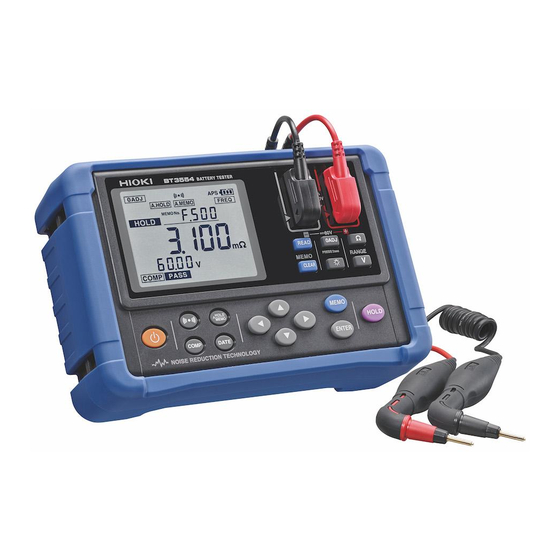
1.2 Product Overview 1.2 Product Overview The 3554 BATTERY HiTESTER is a measuring instrument for judging battery wear by measuring internal resistance, voltage, and terminal temperature* of lead-acid, nickel-cadmium, nickel- hydrogen, lithium-ion, and other types of batteries. * Temperature measurement requires the optional 9460 CLIP TYPE LEAD WITH TEMPERATURE SENSOR. -
Page 24: Features
1.3 Features 1.3 Features Enables measurement without shutting down UPS systems This instrument uses high-precision AC resistance measure- ment technology. Since it is capable of live-wire measure- ment without shutting down the UPS system, it makes it possible to shorten the time required for measurement. Reliable measurement values Since it uses the four-terminal AC method to measure inter- nal resistance, this instrument can obtain reliable measure-... - Page 25 Since the pin can be inserted diagonally in hard-to- reach spots, it also makes measurement possible in virtually any location. Furthermore, pin strength has been improved from that of previous Hioki products. A remote control switch for storing measurement values 索引...
-
Page 26: Names And Functions Of Parts
1.4 Names and Functions of Parts 1.4 Names and Functions of Parts SOURCE Terminal Front Panel Used for connecting the test lead's banana plug to the source SENSE Terminal Used for connecting the test Display lead's banana plug to the sense (⇒... - Page 27 1.4 Names and Functions of Parts Used for selecting configuration settings and chang- ing their values. Used for storing displayed values to memory. Used for setting configuration values. Used for holding or canceling the displayed values. Used for recalling stored measurement values. Used for deleting stored measurement values.
- Page 28 1.4 Names and Functions of Parts Display Data No. Resistance measurement value and unit Voltage Temperature measurement measurement value and unit value and unit Displayed when the zero-adjust feature is enable. Displayed when the auto-hold feature is enable. Displayed when the auto-memory feature is enable. Displayed when the comparator button is turned on.
- Page 29 1.4 Names and Functions of Parts Upper Panel USB Terminal Used for connecting the USB cable. TEMP.SENSOR Terminal EXT.HOLD/MEMO Terminal Used for connecting the Used for the 9466 REMOTE miniplug of the optional 9460 CONTROL SWITCH. with temperature sensor. Rear Panel Battery Cover Fuse Cover This is the cover for the...
-
Page 30: Measurement Flowchart
1.5 Measurement Flowchart 1.5 Measurement Flowchart The measurement workflow is described below. Measurement 1. Attaching the strap ⇒ Preparations ( p.25) 2. Check the instrument's remaining battery power 3. Connecting the test lead 4. Turning the power on 5. Setting clock Setting Range 1. - Page 31 1.5 Measurement Flowchart Zero-adjustment Implement the zero-adjust feature in accordance with the zero- ⇒ p.37) adjust method for the test lead used. When using the 9465-10 Starting Measurement 1. Connect the test lead to the subject of measurement. 2. Read the measurement val- ues.
-
Page 32: External Dimensions
1.6 External Dimensions 1.6 External Dimensions 192 ± 1 mm (7.56" ± 0.04") -
Page 33: Chapter 2 Measurement Preparations
2.1 Attaching the Strap Measurement Chapter 2 Preparations 2.1 Attaching the Strap By attaching the strap, the instrument can be used hung it from the operator's neck. Attach the strap as described below. Attach four ends of the Strap securely to the instru- ment. -
Page 34: Installing Or Replacing The Batteries
2.2 Installing or Replacing the Batteries 2.2 Installing or Replacing the Batteries When using the instrument for the first time, insert eight AA (LR6) alkaline batteries. Before attempting measurement, check to make sure enough battery charge remains. When the battery charge gets low, replace the batteries. - Page 35 2.2 Installing or Replacing the Batteries Turn off the power to the instrument and remove the test lead. Open the battery compartment cover on the rear of the instrument. Insert eight batteries, taking care to use the proper polarities. Replace the battery compartment cover. 索引...
-
Page 36: Connecting The Test Lead
2.3 Connecting the Test Lead 2.3 Connecting the Test Lead To avoid electric shock, be sure to connect the test leads properly. • For safety reasons, when taking measurements, only use the test lead provided with the instru- ment. • The ends of the test leads are sharp. Be careful to avoid injury. - Page 37 2.3 Connecting the Test Lead External Dimensions of the 9465-10 PIN TYPE LEAD 13.5 Unit: mm Conductive contact pin (coaxial pin) Grip Cable lock Banana plug (red) Probe (red) Probe (black) Banana plug (black) SOURCE SENSE Connecting the Test Lead and Remote Control Switch The 9465-10 or the 9772 PIN TYPE LEAD (optional) and the 9466 REMOTE CONTROL SWITCH (optional) can be combined...
-
Page 38: Turning The Power On And Off
2.4 Turning the Power On and Off 2.4 Turning the Power On and Off key to turn the power on and off. Check the clock set- tings when using the instrument for the first time. Powering On All screen elements displayed POWER Press... -
Page 39: Clock-Setting
2.5 Clock-setting 2.5 Clock-setting You can display the date and time by pressing key. Check the clock settings when using the instrument for the first time. 2.5.1 Turning Date-and-time Display On and Off Press key to switch date-and-time display on and off. Date-and time display On Date-and time display off Year... -
Page 40: Setting The Clock
2.5 Clock-setting 2.5.2 Setting the Clock Press key for two sec- onds or longer. This will display the clock- setting screen. (0:00, January 1, 2006) keys change the date and time settings. keys to switch between settings. (12:00, March 15, 2006) Press key to save the date and time settings. -
Page 41: Chapter 3 Measurement
Chapter 3 Measurement To ensure safe measurement, be sure to read this section prior to measuring. Observe the following to avoid electric shock and short circuits. • Do not measure voltages of 60 V DC or higher. • Do not measure grounded voltages of more than 70 V DC. - Page 42 • Internal battery resistance varies considerably depending on charge or discharge status. In order to increase measurement precision, mea- sure under similar conditions (e.g., full battery charge). • Lead-acid batteries (subjects of measurement) have high levels of terminal resistance. For this reason, resistance values may differ between the case side and the tip of a terminal.
-
Page 43: Pre-Operation Inspection
3.1 Pre-operation Inspection 3.1 Pre-operation Inspection Subject of inspection Method of checking Is the fuse worn out? Touch the test lead to the zero-adjust board. If the resistance display still shows a value of "- - . - -" the fuse Is the test lead discon- might be worn out or the test lead dis- nected? -
Page 44: Setting The Measurement Range
3.2 Setting the Measurement Range 3.2 Setting the Measurement Range Set resistance and voltage measurement ranges as described below. 3 mΩ / 30 mΩ / 300 mΩ / 3 Ω Resistance Range Voltage Range 6 V / 60 V Temperature Range (Single range) Since temperature measurement uses a signal range, range setting is unnecessary. -
Page 45: Zero-Adjustment
3.3 Zero-adjustment 3.3 Zero-adjustment Using the zero-adjust feature makes more reliable measure- ments possible by adjusting the resistance-range and voltage- range zero values of the instrument. Using the zero-adjust fea- ture is recommended prior to measurement. The zero-adjust feature sets the current measurement value (adjusted value) at 0 and displays subsequent measurement results. -
Page 46: Shorting Methods For Various Test Leads
3.3 Zero-adjustment 3.3.1 Shorting Methods for Various Test Leads Model 9465-10 PIN TYPE LEAD Short the test leads using the four-terminal AC method, with the included zero-adjust board. As shown in the illustration below, select a hole suited to the distance between terminals on the battery subject to measurement. - Page 47 3.3 Zero-adjustment Model 9460 CLIP TYPE LEAD WITH TEMPERA- TURE SENSOR SOURCE Model 9460 SENSE Model 9467 LARGE CLIP TYPE LEAD SOURCE Model 9467 SENSE Model 9772 PIN TYPE LEAD 索引 Insert the marked (engraved) side into the hole Zero adjustment board...
-
Page 48: Implementing The Zero-Adjust Feature
3.3 Zero-adjustment 3.3.2 Implementing the Zero-adjust Feature Check to ensure that the test leads are connected prop- erly. If a lead is connected to the subject of measurement, dis- connect it. Press key for at least two seconds. This will cause the instrument to wait for adjusted values. Test Lead (black) (red) Press this key for at least two seconds... - Page 49 3.3 Zero-adjustment Begin automatic obtaining of adjusted values. (3 mΩ range) (30 mΩ range) (3 Ω range, voltage range) (300 mΩ range) Keep the test leads shorted until the zero-adjust opera- tion is complete. When the zero-adjust operation is complete, the icon will be displayed and the instrument will return to the measurement state: 索引...
- Page 50 3.3 Zero-adjustment When the screen displays the message "Err": An error results when the zero-adjusted values can- not be obtained correctly. This error could result from any of the following causes: • The adjusted values obtained exceed the 300 count, for either resistance or voltage values. →...
-
Page 51: Canceling The Zero-Adjust Operation
3.3 Zero-adjustment 3.3.3 Canceling the Zero-adjust Operation Pressing the key for at least two seconds while the zero- adjust feature is active will cancel the zero-adjust operation: Press this key for at least two sec- onds Canceling the zero-adjust 索引... -
Page 52: Holding The Display
3.4 Holding the Display 3.4 Holding the Display 3.4.1 Holding Holding the measurement values displayed on screen Press key. The icons will be displayed, and the measurement values will be held: Holding cannot be conduct- ed when the following val- ues are displayed: "- - - -"... -
Page 53: Holding Using The Ext.hold/Memo Terminal
3.4 Holding the Display 3.4.3 Holding Using the EXT.HOLD/MEMO Ter- minal The EXT.HOLD/MEMO terminal can be used for the same pur- poses as key. This requires the optional 9466 REMOTE CONTROL SWITCH. Disconnect the test lead from the battery subject to measurement. -
Page 54: Determining Battery-Wear Judgment Values
3.5 Determining Battery-wear Judgment Values 3.5 Determining Battery-wear Judg- ment Values For determining battery wear, first measure internal resis- tance in a new or good battery, and then set values for judg- ing battery wear. Ex.: When values measured for a new battery are 0.428 mΩ and 2.008 V, set the internal resistance caution value at 0.6 mΩ... -
Page 55: 3.5 Determining Battery-Wear Judgment Values
3.5 Determining Battery-wear Judgment Values Hold the measurement values by pressing key or PRESS button on the remote control switch. Use these measurement values to determine battery wear judgment values. As a battery wears out, in general its internal resistance will grow to approximately 1.5 - 2 times (reference val- ues) that of a new or good battery. -
Page 56: Battery Measurement
3.6 Battery Measurement 3.6 Battery Measurement For determining battery wear, first measure internal resis- tance in a new or good battery, and then set values for judg- ing battery wear. (⇒ p.46) In this example, where values measured for a new battery were 0.428 mΩ... - Page 57 3.6 Battery Measurement Hold the measurement values by pressing key or PRESS button on the remote control switch. Use the measurement values to judge battery wear. <Ex.> Voltage PASS Initial value Wear (2.008 V) FAIL Current value Measurement WARNING (1.864 V) value Current value Initial value...
- Page 58 3.6 Battery Measurement Stabilizing (⇒ p.73) measurement values Storing measurement Measurement values can be values stored by pressing while the values are being held.(⇒ p.44) Loading stored data to (⇒ p.103) a personal computer Configuring threshold Based on these wear judg- values and judging bat- ment values, threshold values tery wear...
-
Page 59: Temperature Measurement
3.7 Temperature Measurement 3.7 Temperature Measurement Use the optional 9460 CLIP TYPE LEAD WITH TEMPERA- TURE SENSOR with temperature sensor to measure battery temperature. Connect the red connector of the clip-type lead with temperature sensor to the SENSE terminal, the black connector to the SOURCE terminal, and the miniplug to the TEMP. - Page 60 3.7 Temperature Measurement C ⇔ ° ° Changing the Unit of Temperature ( Press key to turn the power off. While holding key down, press key. Press key for three seconds or longer. Setting changes This will restart the instrument.
-
Page 61: Chapter 4 Comparator Feature
4.1 Overview Comparator Chapter 4 Feature 4.1 Overview The comparator feature can be used to determine in which of the following ranges measurements fall, by comparing them with preset permissible values and battery measured values: pass, warning, or fail. Up to 200 comparator conditions can be set. Refer to "Section 1.1 Measuring Battery Wear"... -
Page 62: Turning On The Comparator
4.2 Turning On the Comparator 4.2 Turning On the Comparator Press key. The comparator no. will flash. Press key again to return to ordinary settings. Press keys to select the comparator no. In this example, comparator Press keys to select no. -
Page 63: Setting Comparator Permissible Values
4.3 Setting Comparator Permissible Values 4.3 Setting Comparator Permissible Values Set the comparator permissible values (resistance upper limit no. 1, resistance upper limit no. 2, and the voltage lower limit). <Example> Permissible values for a battery with initial values (i.e., resis- tance and voltage values when new or in good condition) of 0.4 Ω... - Page 64 4.3 Setting Comparator Permissible Values Setting Range Press key to select resistance range. Press key to select voltage range. (The position of the decimal point will move.) Press key to save the settings. Resistance upper limit no. 1 is flashing, and icon is displayed.
- Page 65 4.3 Setting Comparator Permissible Values Setting Resistance Permissible Values Press keys to set values resistance upper limit no. 1. Press keys to select digits. In this example, 0.600 Ω has been selected Press key to save the settings. Resistance upper limit no. 2 icon is flashing.
- Page 66 4.3 Setting Comparator Permissible Values Setting Voltage Lower Limit Press keys to set the values of voltage lower limit. Press keys to select digits. In this example, 1.800 V has been selected Press key to save the settings. This will return the display to the measurement screen, with the comparator feature At this point, configuration...
- Page 67 4.3 Setting Comparator Permissible Values Measured Value: PASS Voltage Measurement value Initial PASS value Voltage FAIL lower limit WARNING Resistance Resistance Resistance Initial upper limit upper limit value no. 1 no. 2 Measured Value: WARNING Voltage Initial PASS Measurement value value Voltage FAIL...
- Page 68 4.3 Setting Comparator Permissible Values Comparator Comparison Table Judgment is conducted using the display and the buzzer, as shown in the following table: Resistance upper Resistance upper limit no. 2 limit no. 1 Resistance Resistance Resistance (low) (medium) (high) Voltage (high) PASS WARN FAIL Voltage...
-
Page 69: Setting The Comparator Buzzer
4.4 Setting the Comparator Buzzer 4.4 Setting the Comparator Buzzer When using the comparator feature, the buzzer can be set to sound in accordance with judgment results. The following condi- tions can be set. The initial configuration is "warn/fail (on)." No buzzer sounds regardless of the results of judgment. -
Page 70: Turning Off The Comparator
4.5 Turning Off the Comparator 4.5 Turning Off the Comparator Pressing key when the comparator feature is on will turn off the comparator feature. Comparator feature is on Comparator feature is off • The range keys cannot be used while the com- parator is turned on. -
Page 71: Memory Feature
5.1 Overview Chapter 5 Memory Feature 5.1 Overview Up to 4,800 sets of currently measured values (date and time, resistance, voltage, temperature, comparator permissible val- ues, results of judgment) can be saved. After measurement, saved data can be displayed or transferred to a personal com- puter. -
Page 72: Saving To Memory
5.2 Saving to Memory 5.2 Saving to Memory Pressing key will save the currently measured values. Convenient feature: Auto-memory Feature (⇒ p.75) 5.2.1 Saving Measured Values to Memory Press key. The memory feature will turn If you want to save the data under a different number than the memory no. - Page 73 5.2 Saving to Memory key to hold mea- sured values. When "- -.- -" is displayed, values cannot be held. key to save mea- sured values. Measured values will be saved to the memory no. se- lected. When saving is complete, the next memory no.
-
Page 74: Saving Using The Ext.hold/Memo Terminal
5.2 Saving to Memory 5.2.2 Saving Using the EXT.HOLD/MEMO Terminal The EXT.HOLD/MEMO terminal can be used for the same pur- poses as key. This requires the optional 9466 REMOTE CONTROL SWITCH. To avoid damage to the instrument, do not enter voltage to the EXT.HOLD/MEMO terminal. -
Page 75: Turning Off The Memory Feature
5.3 Turning Off the Memory Feature 5.3 Turning Off the Memory Feature To turn off the memory feature when it is on, hold key down for two seconds or longer. "OFF" will be displayed, and the screen will return to the normal mode. -
Page 76: Reading Saved Data
5.4 Reading Saved Data 5.4 Reading Saved Data Saved measured values can be read and displayed. Press key. This will display the reading screen. Press keys to select the memory no. Press keys to select In this example, C.003 has digits. -
Page 77: Deleting Saved Data
5.5 Deleting Saved Data 5.5 Deleting Saved Data Saved measured values can be deleted as described below. 5.5.1 Deleting a Single Data Set Press key. This will display the reading screen. Press keys to select the memory no. In this example, unit C has Press keys to select been selected... -
Page 78: Deleting An Entire Unit (400 Sets)
5.5 Deleting Saved Data 5.5.2 Deleting an Entire Unit (400 sets) Press key. This will display the reading screen. Press keys to select the memory no. In this example, unit C has been selected. Press key two times. If there is no activity for approximately three sec-... -
Page 79: Deleting All Data (12 Units/4800 Sets)
5.5 Deleting Saved Data 5.5.3 Deleting All Data (12 units/4800 sets) Press key. This will display the reading screen. Press three times. If there is no activity for approximately three sec- onds, the reading screen will be displayed. "-.- - -" is flashing This display indicates that all units have been selected. - Page 80 5.5 Deleting Saved Data...
-
Page 81: Chapter 6 Other Features
6.1 Averaging Feature Chapter 6 Other Features 6.1 Averaging Feature When measured values are unstable, they can be stabilized using averaging. The number of times averaging is conducted can be selected from four, eight, or 16 times. When using the averaging feature, icon is displayed on the screen. -
Page 82: Auto-Hold Feature
6.2 Auto-hold Feature 6.2 Auto-hold Feature This feature can be used to recognize automatically the stability of measured values and to hold measured values. Configuring the Auto-hold Feature Press several times key to display the icon. Auto- Auto-hold memory Auto-hold & Auto-memory Releasing the Hold Release the hold by pressing... -
Page 83: Auto-Memory Feature
6.3 Auto-memory Feature 6.3 Auto-memory Feature This feature saves measured values to memory automatically, immediately after the values have been held. Configuring the Auto-memory Feature Press several times key to display the icon. At this point, the memory feature is in effect. Auto- Auto-hold memory... -
Page 84: Auto-Power-Save Feature (Aps)
6.4 Auto-power-save Feature (APS) 6.4 Auto-power-save Feature (APS) The auto-power-save feature can be used to control the instru- ment's power consumption. When any of the following condi- tions has continued for approximately ten seconds with no keys pressed, power to the instrument will be turned off automatically. •... - Page 85 6.4 Auto-power-save Feature (APS) Turning the Auto-power-save Feature On and Off Press key to turn the power off. While holding down, press key. This will display the auto- power-save configuration screen. On is flashing Using keys, select "OFF." To turn the auto-power-save feature on, select "On."...
-
Page 86: System Reset
6.5 System Reset 6.5 System Reset These steps can be used to restore the instrument to its initial configuration conditions. However, note that the following settings will not be deleted: • Date and time • Saved measurement data (4,800 data sets) •... - Page 87 6.5 System Reset Initial Configuration Conditions (Factory Settings) Resistance range 3.000 mΩ Voltage range 6.000 V Average range Zero-adjustment feature Releasing Auto-hold feature Auto-memory feature Comparator feature Comparator buzzer setting WARNING/FAIL (ON) Auto-power-save feature • When the system-reset screen has been dis- played unintentionally, turn the power on again.
-
Page 88: Battery Level Indicator
6.6 Battery Level Indicator 6.6 Battery Level Indicator The battery level indicator is displayed in the upper right-hand area of the screen. Battery level indicator Battery level Battery status indicator Battery condition when new alkaline batteries have been inserted. Battery condition after approximately four hours of use. -
Page 89: Connecting With A Computer
Connecting with Chapter 7 a Computer Notation • Unless otherwise specified, “Windows” represents Windows 98SE, Me, 2000, or Windows XP. • Dialog box represents a Windows dialog box. • Menus, commands, dialogs, buttons in a dialog, and other names on the screen and the keys are indicated in brackets. Mouse Operation Click Press and quickly release the left button of... -
Page 90: Overview
In addition, clock settings and mea- surement data can be deleted. Editing a table of permissible values ⇒ on the 3554 ( p.112) Reading data from the 3554’s internal ⇒ memory ( p.117) USB cable Personal computer... -
Page 91: Recommended Operating Environment
20 MB or more of disk space (Additional hard-disc space required for storing record data) Interface USB Ver.1.1 or later (Only one model 3554 instrument can be connected to the PC at a time.) 7.1.2 Composition of CD Folder Japanese... -
Page 92: Installing The Software
Start up the personal computer. Stop all applications being executed on the computer (recommended). Insert the CD that came with the instrument (Application Software for 3554) into the computer's CD-ROM drive. Application Software for 3554 Once the computer has detected the... - Page 93 7.2 Installing the Software When the installShield Wizard appears, click the [Next] button. Click Enter your username and company name, and then click [Next]. (1) Enter (2) Enter (3) Click 索引...
- Page 94 7.2 Installing the Software Click [Next]. Click [Browse] to change the directory to which the application will be installed. (1) Click (2) Click Click [Install]. Click...
- Page 95 When the installShield Wizard Complete appears, click [Finish] button. Click After the installation is complete, complete the installation process by ejecting the CD from the CD-ROM drive. 索引 The latest version of Application Software for 3554 can be downloaded from the Hioki Website. URL: http://www.hioki.co.jp/...
-
Page 96: Uninstalling (Removing) The Application
7.2 Installing the Software 7.2.2 Uninstalling (removing) the Application If Application Software for 3554 is active, be sure to close the application before uninstalling it. Select the [Add or Remove Programs] in the Control Panel, under the Start menu. Click... -
Page 97: Installing The Usb Driver
Do not plug in or unplug the USB cable while the instrument is operating. After installing Application Software for 3554, the USB driver can be installed by connecting the instrument with the personal com- puter using the USB cable. (Once Application Software for 3554 has been installed, there is no need to reinsert the CD into the computer's CD-ROM drive to install the driver.) - Page 98 7.3 Installing the USB Driver Following the instructions in the [Found New Hardware Wizard] dialog box, install the driver. (WindosXP used) Procedures for using the Found New Hardware Wizard differ by operating system used. Driver installation meth- ods for each operating system are described below. "Section 7.3.1 For WindowsXP"...
-
Page 99: For Windowsxp
7.3 Installing the USB Driver 7.3.1 For WindowsXP [Found New Hardware Wizard] dialog box will appear. Select [No, not this time], and then click [Next]. Depending on the version of Windows XP used, instead of displaying this dialog box the computer might go directly to the dialog box in Step instead. - Page 100 In the location field, type [C:\Program Files\HIOKI\3554\Driver] and then click [Next]. (If you have installed Application Software for 3554 in another directory, enter the path to that directory instead of the one shown in the example above.) (1) Click...
- Page 101 7.3 Installing the USB Driver Click [Continue Anyway]. After Windows XP checks the software, it will display a warning stating that the software has not been certified by Microsoft. Click "Continue Anyway." Click Windows will begin copying the driver files. When installation is complete, the next dialog will appear.
-
Page 102: For Windows2000
7.3 Installing the USB Driver 7.3.2 For Windows2000 [Found New Hardware Wizard] dialog box will appear and then click [Next]. Click Select [Search for a suitable driver for my device] then click [Next]. (1) Click (2) Click... - Page 103 In the location field, type [C:\Program Files\HIOKI\3554\ Driver] and then click [OK]. (If you have installed Application Software for 3554 in another directory, enter the path to that directory instead of the one shown in the example above.) (2) Click (1) Enter 索引...
- Page 104 7.3 Installing the USB Driver The driver can also be installed by inserting the included CD into the computer's CD-ROM derive and entering [X:\Driver] in the location field. ([X] in the above file location indicates the CD-ROM drive. The letter allocated to the CD-ROM drive may vary by computer.) Click [Next].
-
Page 105: For Windowsme
7.3 Installing the USB Driver 7.3.3 For WindowsMe [Found New Hardware Wizard] dialog box will appear. Select [Specify the location of the driver], and then click [Next]. (1) Click (2) Click 索引... - Page 106 [C:\Program Files\HIOKI\3554\ Driver] and then click [Next]. (If you have installed Application Software for 3554 in another directory, enter the path to that directory instead of the one shown in the example above.) (1) Click (2) Select...
- Page 107 7.3 Installing the USB Driver Click [Next]. Click Windows will begin copying the driver files. When installation is complete, the next dialog will appear. Click [Finish]. Click (In some cases, it may take some time until the [Found New Hardware Wizard] closes.) 索引...
-
Page 108: For Windows98Se
7.3 Installing the USB Driver 7.3.4 For Windows98SE [Found New Hardware Wizard] dialog box will appear and then click [Next]. Click Select [Search for the best driver for your device] then click [Next]. (1) Click (2) Click... - Page 109 [C:\Program Files\HIOKI\3554\ Driver] and then click [Next]. (If you have installed Application Software for 3554 in another directory, enter the path to that directory instead of the one shown in the example above.) (1) Select (2) Click...
- Page 110 7.3 Installing the USB Driver Click [Next]. Click Windows will begin copying the driver files. When installation is complete, the next dialog will appear. Click [Finish]. Click (In some cases, it may take some time until the [Found New Hardware Wizard] closes.)
-
Page 111: Using The Software
USB cable Personal computer Model 3554 • Only one 3554 instrument may be connected to a computer at one time. • When connected to a computer using the USB 索引 cable, the instrument will shift to PC mode and cease measurement operations. -
Page 112: Starting The Software
7.4 Using the Software 7.4.2 Starting the Software Double-click on the icon on the computer's desk- top. The software's initialization screen will appear. When the following message has been displayed, check the USB cable connection or the power supply and then click [OK]. -
Page 113: Clock-Setting
7.4 Using the Software 7.4.3 Clock-setting Click [SET COMP/Clock] on the initialization screen. Click Click [Set Clock]. Click 索引... - Page 114 [Set] without changing them. (1) Set (2) Click The clock settings will be finalized and transmitted to the 3554 instrument. If you leave the clock setting screen by clicking [Back] without clicking [Set], the clock settings will not be saved.
-
Page 115: Preparing A New Table Of Permissible Values
7.4 Using the Software 7.4.4 Preparing a New Table of Permissible Val- Up to 200 tables of comparator permissible values can be pre- pared. Click [SET COMP/Clock] on the initialization screen. Click Click [COMP Table]. 索引 Click... - Page 116 7.4 Using the Software Click [New File]. Click [Edit Comparator Table] will appear.
- Page 117 7.4 Using the Software Entering configurations for each table. (In the illustration above, resistance upper limit no. 1 has been set at 130.0 mΩ, resistance upper limit no. 2 at 140.0 mΩ [300 mΩ range], and the voltage lower limit has been set at 1.500 V [6 V range]).
-
Page 118: Editing Files Of Permissible Values
7.4 Using the Software 7.4.5 Editing Files of Permissible Values Click [SET COMP/Clock] on the initialization screen. Click Click [COMP Table]. Click... - Page 119 7.4 Using the Software Click [Edit File]. Click Click comparator table file and then click [Open]. (1) Click (2) Click Editing configurations for each table. Refer to "Section 7.4.4 Preparing a New Table of Permis- sible Values" (⇒ p.107) for how to set. 索引...
-
Page 120: Editing A Table Of Permissible Values On The 3554
7.4 Using the Software 7.4.6 Editing a Table of Permissible Values on the 3554 Click [SET COMP/Clock] on the initialization screen. Click Click [COMP Table]. Click... - Page 121 7.4 Using the Software Click [Edit 3554 data]. Click Following dialog box will appear and then Click [Yes]. Click Receipt of the table of permissible values will begin. 索引...
- Page 122 7.4 Using the Software After receipt of the table of permissible values is com- plete, click [OK]. Click Editing configurations for each table. Refer to "Section 7.4.4 Preparing a New Table of Permis- sible Values" (⇒ p.107) for how to set. Transfer takes approximately three seconds.
-
Page 123: Transferring Tables Of Permissible Values
7.4 Using the Software 7.4.7 Transferring Tables of Permissible Values Transferring tables of permissible values will over- write all tables of permissible values stored on the instrument. Click [Transfer] on the Edit Comparator Table dialog box. Click Following dialog box will appear. Click [Yes] to transfer the data if desired. - Page 124 7.4 Using the Software If the data has not already been saved, the following dia- log box will appear. Click [Yes] to save the data if desired. Click Tables of permissible value transfer will begin. After tables of permissible value transfer is complete, click [OK].
-
Page 125: Reading Data From The 3554'S Internal Memory
7.4 Using the Software 7.4.8 Reading Data from the 3554's Internal Memory The application can be used to read measurement data saved to the instrument's internal memory. Click [Read/Delete Data] on the initialization screen. Click Click [Read Data]. 索引 Click... - Page 126 7.4 Using the Software Click the number of the unit to read. Click [ALL UNITs] to read all units. Click If no data has been saved to the instrument's internal memory, the unit numbers will be covered in a mesh-like pattern and will not be available for choosing.
- Page 127 7.4 Using the Software Data transfer will begin. • Transfer of a single unit (400 units of data) takes approximately eight seconds. • Transfer of all units (4,800 units of data) takes approxi- mately 90 seconds. • The transfer times given are approximations. The actual time needed may vary depending on the processing speed of the personal computer used.
- Page 128 7.4 Using the Software To open the read data, open the file in the directory desig- nated in step 4. (Example: opening the data in Microsoft Excel) In this way, the data read from the instrument can be checked.
-
Page 129: Deleting Data From The 3554'S Internal Memory
7.4 Using the Software 7.4.9 Deleting Data From the 3554's Internal Memory The application can be used to read measurement data saved to the instrument's internal memory. Click [Read/Delete Data] on the initialization screen. Click Click [Delete Data]. 索引 Click... - Page 130 7.4 Using the Software Click the number of the unit to delete. Click [ALL UNITs] to delete all units. Click If no data has been saved to the instrument's internal memory, the unit numbers will be covered in a mesh-like pattern and will not be available for choosing.
-
Page 131: Closing The Application
7.4 Using the Software 7.4.10 Closing the Application Click [Exit] on the initialization screen. (1) Click 索引 (2) Click A confirmation dialog will appear. Click [Yes]. Application Software for 3554 will close. - Page 132 7.4 Using the Software...
-
Page 133: Chapter 8 Specifications
8.1 General Specifications Chapter 8 Specifications 8.1 General Specifications Measurement • Measurement of battery internal resistance modes • Measurement of battery terminal voltage (DC voltage only) • Temperature measurement Measurement (After 0 adjustment) range Ω Ω 0.000 m to 3.100 (Four-range structure) •... - Page 134 8.1 General Specifications Detection of "- - - -" is displayed constant-current irregularities Disconnect "- - - -" is displayed detection Processing "OF" is displayed excess input Input terminals • Resistance, voltage measurement termi- nals Banana-plug type Maximum input voltage: ±...
- Page 135 8.1 General Specifications Zero-adjustment Details of Measured values upon implementation operation (upon obtaining adjusted values) are set at zero Initial status Adjustment Up to 300 counts for each range range (resistance, voltage) Auto holding of measured values Details of Holding (ceasing updating of) displayed val- operation Hold method (1) Pressing the...
- Page 136 8.1 General Specifications Memory Feature Details of While the measured values are being held, operation press the key to save them to the instru- MEMO ment's internal memory. When the auto-memory feature is on, mea- sured values will be saved to the instrument's internal memory when held.
- Page 137 8.1 General Specifications Auto-memory Feature Details of Saves measured value data automatically operation when held. Saved data can be cancelled by pressing the key. CLEAR Initial status Auto-power-save Feature (power on option) Details of Cuts off power to the instrument automatically operation when it has not been used for ten minutes or longer and detection of constant-current irregu-...
- Page 138 8.1 General Specifications Clock Features 24-hour clock; automatically adjusts for leap year Precision +/- approximately 4 minutes/month Other features Runs on internal backup lithium battery Battery life: approximately 10 years Data Stored (to internal EEPROM [nonvolatile memory]) Measurement range configuration, zero-adjust values, averag- ing settings, measurement data saved to memory, comparator permissible values, comparator nos., memory settings, mem- ory nos., reading nos., buzzer settings, auto-hold settings,...
- Page 139 8.1 General Specifications × × × Dimensions Approx. 192W 121H 55D mm / 7.56"W × 4.76"H 2.17"D (sans protrusions) Mass Approx. 790 g / 27.9 oz. (within batteries) Dielectric Between all measurement terminals and strength USB terminal: AC 1.5 kV; 15 seconds; cutoff current: 5 mA Maximum input Between positive and negative measurement voltage...
-
Page 140: Accuracy
8.2 Accuracy Accessories Model 9465-10 PIN TYPE LEAD... 1 USB cable ..........1 Application Software CD ....... 1 Strap ............1 Instruction manual ......... 1 Carrying case ........1 Zeroadjustment board ......1 LR6 alkaline batteries......8 Fuse (216.315, Littelfuse,INC) (F315mAH / 250 V) ....... -
Page 141: Resistance Measurement
8.2 Accuracy Resistance measurement • Temperature coefficient: 3 mΩ range: (± 0.01 rdg. ± 0.8 dgt.)/°C Other range: (± 0.01 rdg. ± 0.5 dgt.)/°C ± • Measurement current reliability: ± • Measurement current frequency: 1 kHz 30 Hz Maximum Measured Range displayed Resolution... -
Page 142: Communications
8.3 Communications 8.3 Communications USB Interface Hardware Uses RS-232C/USB converter Operating method When connecting the instrument to a per- sonal computer via the USB cable, the instrument shifts to PC mode. Measurement ceases when in PC mode. Details of Output of various settings and saved data communication Transfer method Start-stop synchronization, Full duplex... -
Page 143: Maintenance And Service
Include cushioning material so the instru- ment cannot move within the package. Be sure to include details of the problem. Hioki cannot be responsible for damage that occurs during ship- ment. - Page 144 9.1 Troubleshooting Before Returning for Repair If the instrument appears to be operating unusually, check the following: Symptoms Items to check/countermeasures Nothing displayed Are the batteries out of power? → screen even If so, replace them with new batteries. after pressing (⇒...
- Page 145 9.1 Troubleshooting Symptoms Items to check/countermeasures temperature dis- Has the 9460 CLIP TYPE LEAD played on screen when WITH TEMPERATURE SENSOR using 9460 CLIP with temperature sensor been con- TYPE LEAD WITH TEM- nected correctly? → PERATURE SENSOR If not, connect it correctly. (⇒ with temperature sensor.
-
Page 146: Error Display
Zero-adjust Ensure the probe is con- failure nected correctly and conduct the zero adjustment again. (⇒ p.37) no AdJ Irregularity in Repairs required. adjustment Contact your dealer or Hioki data representative. Er10 Internal vari- Er11 able error Er12 Er20 Er21... -
Page 147: Frequently Asked Questions
9.3 Frequently Asked Questions 9.3 Frequently Asked Questions 9.3.1 Can Manganese Batteries be Used? The period for which the instrument can be used continuously (approximately 10 hours) is mea- sured using alkaline batteries. Note that use of manganese batteries will reduce this time con- siderably (to approximately three hours). -
Page 148: Setting Permissible Values
9.3 Frequently Asked Questions 9.3.3 Setting Permissible Values For determining battery wear, first measure internal resistance in a new or good battery. The graph below shows the relation between storage capacity and initial value of internal resistance in a lead-acid battery. "CS,"... -
Page 149: Replacing The Fuse
9.4 Replacing the Fuse 9.4 Replacing the Fuse When the instrument's fuse has burned out, replace it as described below. • To avoid electric shock when replacing the fuse, first disconnect the test leads from the battery to be measured. After replacing the fuse, replace the fuse cover and screws before using the instrument. -
Page 150: Replacing The Test Lead Pin
9.5 Replacing the Test Lead Pin 9.5 Replacing the Test Lead Pin The conductive-tip contact pin is replaceable. Replace the pin with a new one if it is broken or worn. One-piece conductive-tip contact pins with a plastic pin base are available separately. Turn off the power of the instrument and remove the cable. -
Page 151: Cleaning
9.6 Cleaning Fasten a new pin. Press the tip of the pin against a hard board so that the pin won’t spring out, and push the con- nector onto the pin. Model 9465-90 tip pin Assemble the pin type lead in the reverse order of disas- sembling. -
Page 152: Discarding The Instrument
9.7 Discarding the Instrument 9.7 Discarding the Instrument • When disposing of this instrument, remove the lithium battery and dispose of battery and instrument in accordance with local regulations. • To avoid electrocution, turn off the power switch and disconnect the test lead before removing the lithium battery. -
Page 153: Chapter 10 Appendix
Appendix 10.1 Effects of Extending the Measure- ment Lead and Induced Voltage The test lead extension is normally performed by Hioki. If you want extension performed, contact your dealer or Hioki repre- sentative. Users should not extend the measurement leads. -
Page 154: Effect Of Eddy Currents
10.2 Effect of Eddy Currents 10.2 Effect of Eddy Currents The AC current generated in the instrument induces eddy cur- rents in the surrounding metallic plates, which generate induced voltage in the test lead. Since the phase of this induced voltage is shifted from that of the AC current (reference signal) by 180 degrees, it cannot be eliminated by the synchronous detection circuit, resulting in measurement errors. -
Page 155: Ac Four-Terminal Method
10.3 AC Four-terminal Method 10.3 AC Four-terminal Method The instrument uses the AC four-terminal method, so that resis- tance measurement can be carried out with the resistance of the leads and the contact resistance between the leads and the object to be measured canceled out. The following figure shows the principle of the AC four-terminal measurement method. - Page 156 10.3 AC Four-terminal Method Impedance Reactance Effective resistance If the lead resistance, the contact resistance between measured object and lead, or the contact resistance between the lead and the instrument increases, the instrument can no longer supply normal current to the measured object, resulting in an abnormal measurement status indicated by "- - - -"...
-
Page 157: Effects Of Current Density
Use of Hioki's 9453 four-terminal lead or a similar lead to detect voltage on the inner side of the sources of 索引... - Page 158 10.4 Effects of Current Density Ω 0.1 m Ω 0.2 m Ω 0.3 m Ω 0.4 m Current Current source source (Illustration 1) A plot of the equipotential lines of metal plate showing current distribution at 50 µV intervals when applying a 1 A current at the endpoints of the plate (W 300 X L 370 X t 0.4) As shown in Illustration 2, it is desirable to locate the sensor ter- minals within the plate's W or t value of the sense terminals:...
-
Page 159: Synchronous Detection System
10.5 Synchronous Detection System 10.5 Synchronous Detection System The figure below shows an equivalent circuit for a battery. If the measured object exhibits other electrical characteristics in addi- tion to resistance, as shown in this figure, we can use the syn- chronous detection system to obtain the effective resistance of the object. - Page 160 10.5 Synchronous Detection System Given "v1," a reference signal voltage for the AC current gener- ated in the instrument, and "v2," the signal voltage for use in synchronous detection, these parameters may be expressed by the equation given below. θ of v2 shows the phase difference against v1 and is generated by the reactance.
-
Page 161: Test Lead Options
10.6 Test Lead Options 10.6 Test Lead Options 10.6.1 Model 9460 CLIP TYPE LEAD WITH TEM- PERATURE SENSOR Resistance, voltage, and temperature can be measured simulta- neously. Banana plug (red) Clip (red) Miniplug (TEMP SENSOR) Temperature sensor Clip (black) Banana plug (black) SOURCE SENSE 10.6.2 Model 9466 REMOTE CONTROL SWITCH... -
Page 162: Lead
10.6 Test Lead Options 10.6.3 Model 9467 LARGE CLIP TYPE LEAD These can be clipped to samples in relatively thick bar form. Four-terminal measurement can be conducted just by clipping these to the subject. Distance between the split and the probe: approximately 250 mm Distance between the connector and the split: approximately 850 mm... -
Page 163: Calibration Procedure
(DC) resistance will not equal effective resistance (impedance; displayed on the instrument). • Connect the instrument to the standard resistor as shown below: Standard resistor Model 3554 SOURCE - Hi SENSE - Hi 索引 SENSE - Lo SOURCE - Lo... -
Page 164: Voltmeter Calibration
This will turn off the disconnect-detection feature. Restart the instrument after calibration. This will turn on the disconnect- detection feature again. DC generator Model 3554 SENSE - Hi SENSE - Lo SOURCE - Hi SOURCE - Lo... - Page 167 HIOKI 3554 BATTERY HiTESTER Instruction Manual Publication date: March 2006 Edition 1 Edited and published by HIOKI E.E. CORPORATION Technical Support Section All inquiries to International Sales and Marketing Department 81 Koizumi, Ueda, Nagano, 386-1192, Japan TEL: +81-268-28-0562 / FAX: +81-268-28-0568 E-mail: os-com@hioki.co.jp...
- Page 168 HEAD OFFICE 81 Koizumi, Ueda, Nagano 386-1192, Japan TEL +81-268-28-0562 / FAX +81-268-28-0568 E-mail: os-com@hioki.co.jp / URL http://www.hioki.co.jp/ HIOKI USA CORPORATION 6 Corporate Drive, Cranbury, NJ 08512, USA TEL +1-609-409-9109 / FAX +1-609-409-9108 3554A981-00 06-03H Printed on recycled paper...
Need help?
Do you have a question about the 3554 and is the answer not in the manual?
Questions and answers