
Related Manuals for Hioki POWER HiTESTER 3193


Summary of Contents for Hioki POWER HiTESTER 3193
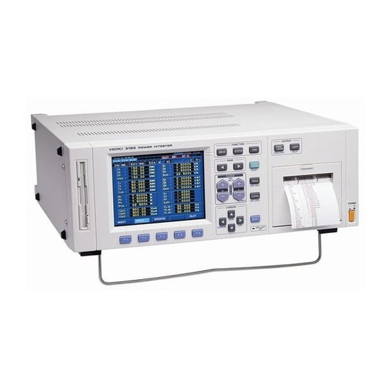
- Page 1 INSTRUCTION MANUAL For... 3193 POWER HiTESTER 1.800.561.8187 information@itm.com www. .com...
- Page 2 1.800.561.8187 information@itm.com www. .com...
- Page 3 1.800.561.8187 information@itm.com www. .com...
- Page 4 1.800.561.8187 information@itm.com www. .com...
- Page 5 1.800.561.8187 information@itm.com www. .com...
- Page 6 1.800.561.8187 information@itm.com www. .com...
- Page 7 1.800.561.8187 information@itm.com www. .com...
- Page 8 1.800.561.8187 information@itm.com www. .com...
- Page 9 Introduction Thank you for purchasing this HIOKI "3193 POWER HiTESTER." To get the maximum performance from the unit, please read this manual first, and keep this at hand. Inspection When the unit is delivered, check and make sure that it has not been damaged in transit.
-
Page 10: Safety Notes
Safety Notes This Instruction Manual provides information and warnings essential for operating this equipment in a safe manner and for maintaining it in safe operating condition. Before using this equipment, be sure to carefully read the following safety notes. DANGER Safety symbols The following symbols are used in this Instruction Manual to indicate the relative importance of cautions and warnings.•... - Page 11 The specifications in this manual include figures for "measurement accuracy" when referring to digital measuring instruments, and for "measurement tolerance" when referring to analog instruments. • • f .s. (maximum display or scale value, or length of scale) Signifies the maximum display (scale) value or the length of the scale (in cases where the scale consists of unequal increments or where the maximum value cannot be defined).
-
Page 12: Measurement Categories (Overvoltage Categories)
Measurement categories (Overvoltage categories) 9600, 9601 and 9602 instrument comply with CAT III (600 V or less)/ CAT II (600 to 1000 V) safety requirements. 9603 instrument complies with CAT I safety requirements. To ensure safe operation of measurement instruments, IEC 61010 establishes safety standards for various electrical environments, categorized as CAT I to CAT IV, and called measurement categories. - Page 13 Notes on Use In order to ensure safe operation and to obtain maximum performance from the unit, observe the cautions listed below. DANGER WARNING Notes on Use 1.800.561.8187 information@itm.com www. .com...
- Page 14 CAUTION Notes on Use 1.800.561.8187 information@itm.com www. .com...
- Page 15 • •All options for this unit are factory-fitted, but it is also possible to add NOTE options at a later date after purchase. In this case, however, it is necessary for the unit to be returned to headquarters. • •With the appropriate combination of direct connection input units, this unit can function as either an AC power meter or dual AC/DC power meter.
- Page 16 viii • •When the input is less than a certain level of measurement range, depending NOTE on using the input unit, the display value is forced to zero. See the specifications of the input unit to be used. • •When measuring a high frequency voltage to earth (for example the secondary side of an inverter), errors may occur in the measurement values.
-
Page 17: Chapter 1 Overview
Chapter 1 Overview 1.1 Product Overview The 3193 POWER HiTESTER is a power meter that can test any type of line ranging from single-phase lines to three-phase four-wire lines. Based on the voltage, current, and active power measurements, this unit calculates and displays reactive power, apparent power, power factor, phase angle, and efficiency. - Page 18 1.2 Features The 3193 POWER HiTESTER features a safe design that complies with the IEC61010-1 safety standard. This single power meter is capable of measuring power on all types of power lines, ranging from single-phase lines to three-phase four-wire lines by installing the input units.
- Page 19 It is possible to measure peak values of a voltage or current waveform. Also, using the peak hold function, motor surge current peak values, and the peak values of effective values can be measured. For current and active power, positive, negative, and total integrated values are provided.
- Page 20 The built-in floppy disk drive facilitates data saving when required, and automatic saving at preset times. It is also possible to save the unit settings and reload them to restore the previous state. Upgrades of the unit are also supported. These output specified items, with an output of •...
-
Page 21: Names And Functions Of Parts
Chapter 2 Names and Functions of Parts 2.1 Panels and Key Operation 2.1 Panels and Key Operation 1.800.561.8187 information@itm.com www. .com... - Page 22 Changes to the measurement value display screen Changes to the settings display screen Used for setting the file name of the floppy disk, and saving and recalling unit settings. In the MEAS and STATUS screens, used to switch display for the item in the second row from the top.
- Page 23 2.1 Panels and Key Operation 1.800.561.8187 information@itm.com www. .com...
-
Page 24: Screen Configuration
2.2 Names and Configuration of Screen 2.2.1 Screen Configuration The three basic screens are the MEAS (measurement) screen, the STATUS screen, and the FDD (floppy disk drive) screen. Pressing the key on the panel switches to the corresponding screen. This configuration is when all options are installed. - Page 25 2.2.2 MEAS Screen (Measurement Screen) This screen displays measurement results. The displays available depend on the options installed. Switch from one display to another using the key on the front panel. In this case the second row of cursor positions from the top of the screen shows the currently displayed page.
- Page 26 #204.tif • •The subscript numbers on symbols indicate channels. For example, "U " NOTE indicates that the voltage measured on input unit channel 1 is displayed. The indication "U " indicates that the SUM value of the voltages measured on input unit channels 1, 2 and 3 is displayed. •...
- Page 27 • • R equired items (except harmonics, flicker, and integration values) can be selected from all of the measurements being made and displayed. • • T he screen format can be selected to show 4, 8, or 16 items. #207.tif #208.tif #232-9.tif 2.2 Names and Configuration of Screen...
- Page 28 By combining measurement values (active power, motor power), this calculates and displays the efficiency. #232-10.tif This is displayed when the optional 9603 EXTERNAL SIGNAL INPUT UNIT is installed. The motor power (Pm) is displayed only when the unit settings for channel A is torque, for channel B is number of rotating (rpm). #232-11.tif This is displayed when the optional 9605 HARMONIC/FLICKER...
- Page 29 2.2.3 STATUS Screen (Setting Screen) This screen provides various settings. The screens correspond to the installed options. Switch from one display to another using the key on the front panel. In this case the second row of cursor positions from the top of the screen shows the currently displayed page.
- Page 30 This shows the settings for the response, averaging function, the interval time, timer time, and real-time control time. #CHANGE 233-4.tif This shows the settings for the output to FDD/printer, printing direction, saving screen color on FD, D/A output, frequency measurement function source, and frequency range of the unit.
- Page 31 This sets the items to be substituted in the efficiency calculation expression. #233-7.tif This is displayed when the optional 9603 EXTERNAL SIGNAL INPUT UNIT is installed, and some settings are made for the 9603. #233-8.tif This is displayed when the optional 9605 HARMONIC/FLICKER is installed.
- Page 32 2.2.4 FDD Screen This supports file name setting of a floppy disk, and saving and loading of the unit settings. #234.tif 2.2 Names and Configuration of Screen 1.800.561.8187 information@itm.com www. .com...
- Page 33 2.3 Indicators The following indicators are shown by panel key operation. #235.tif Indicates when the key is pressed. Pressing again goes off. Indicates key lock state (red), and remote state by GP-IB/RS- 232C (yellow). Indicates the displays are held. Indicates the peak hold function is active. Indicates total value after time averaging.
- Page 34 2.4 Peak Over Indication If the input voltage or current waveform peak exceeds six times the range value, a "PEAK" indication appears. These indications appear on the screen below the channel number, the voltage indication on the left and the current indication on the right, so that even a "PEAK"...
-
Page 35: Preparation For Measurement
Chapter 3 Preparation for Measurement 3.1 Notes on Use DANGER 3.1 Notes on Use 1.800.561.8187 information@itm.com www. .com... - Page 36 WARNING CAUTION • •For 3P3W, 3V3A measurement, the active power values for each channel are NOTE found from the voltages between lines and the currents on each line, and have no individual significance. • •If the maximum values of the voltage or current on the lines being measured exceed the measurement range of this unit, use an external voltage transformer (PT) or current transformer (CT).
-
Page 37: Basic Operating Procedure
3.2 Basic Operating Procedure • • • • • • • • • • • • • • • • • • • • • • • • • • • • • • • • • • • • • OFF •... - Page 38 3.3 Powering On WARNING CAUTION 1. Confirm that the voltage of the power supply being used matches the supply voltage indicated on the rear panel of the unit. 2. Confirm that the power switch on the front panel is off. 3.
- Page 39 3.4 Connecting the Direct Input Unit The following diagrams show the connections in various modes when using the 9600 and 9601 AC/DC DIRECT INPUT UNIT AC DIRECT INPUT UNIT 3.4 Connecting the Direct Input Unit 1.800.561.8187 information@itm.com www. .com...
- Page 40 3.4 Connecting the Direct Input Unit 1.800.561.8187 information@itm.com www. .com...
- Page 41 3.5 Connecting the Clamp Input Unit The following diagrams show the connections in various modes when using the 9602 AC/DC CLAMP INPUT UNIT 3.5 Connecting the Clamp Input Unit 1.800.561.8187 information@itm.com www. .com...
- Page 42 3.6 Measurement Losses This unit is designed to have low measurement losses, and an extremely small effect on the power measurement values, but the following variant connection methods may be used to further reduce the effect of measurement losses. (1) When the voltage input is connected to the power supply side, the measurement includes losses from the input resistance of the current input terminals, but this yields the minimum measurement losses when the measured voltage is high and the measured current is low.
-
Page 43: Error Messages
3.7 Error Messages If an error message appears when the instrument is turned• • O N, the unit has malfunctioned. Please contact your local• • d istributor for further assistance. 3.7 Error Messages 1.800.561.8187 information@itm.com www. .com... -
Page 44: System Reset
3.8 System Reset To reset settings to the initial factory settings, there are following two methods. Turn the power on pressing the key until beep sounds. 1. Press the key to display the screen. 2. Using the keys, move the cursor to "SYSTEM RESET", and press the ) key. - Page 45 3.9 Operations During Power Failure CAUTION The screen display goes blank, and after power restoring redisplays the screen. However, the screen is displayed before power failure, the MEAS screen for channel 1 is redisplayed. If the display data was being held when power was lost, all of the data that was being held is not retained.
- Page 46 After the power is restored, a character string indicating that there was a power failure is output. (time of power failure and restoring) The data being saved is invalid. In the worst case there is a possibility of the file itself being corrupted. The setting is invalid.
- Page 47 Chapter 4 Setting and Using the Basic Functions 4.1 Setting the Wiring Mode (1P2W to 3P4W) This unit can have up to six input unit channels, allowing a single unit to measure anything from six 1P2W lines to two 3P4W systems. The connection mode of each channel also appears on the screen as shown below.
- Page 48 1. Press the key, then use the keys to display the " " page. 2. Using the keys, move the cursor to the " " item. 3. Press ) to switch to the connection setting screen. 4. In the Wiring screen, a list of the installed input units appears.
- Page 49 • •It is only possible to select from the combinations shown in the connection NOTE setting screen. For combinations 1P3W and above, adjacent units must be of the same type. • •When using the 9602 , only a combination of AC/DC CLAMP INPUT UNIT the same clamp type can be selected.
- Page 50 4.2 Setting the Coupling Mode (DC/AC+DC/AC) 42-1.tif ##42-2.tif -3 The coupling mode can be selected according to the measurement being performed. 1. Switch to display the channel for which you wish to change the setting. 2. Press the key, then use the key to change.
- Page 51 4.3 Switching the Voltage Range and Current Range When the voltage range and current range is displayed on the screen for each channel, it is also possible to change the ranges directly with the panel keys. This is also possible from the STATUS screen in the " "...
- Page 52 1. Switch to display the channel for which you wish to change the setting. 2. Hold down the panel (+,-) key until the desired setting range is displayed. 3. To set auto ranging, hold down the panel (+) key or press both (+,-) keys simultaneously. 4.
- Page 53 4.4 Effective Value (RMS) or Mean Rectified Value (MEAN) Selection For voltage and current measurement, this unit has two different rectification circuits, which can be selected according to the signal being measured. 44-1.tif • • T o switch the voltage, press the key, and key on the U side.
- Page 54 4.5 Setting the Scaling (PT/CT/SC Ratios) This is used for setting the ratio (PT ratio or CT ratio) when using an external voltage transformer (PT) or current transformer (CT), and the scaling factor (SC ratio) for conversion of the active power to other physical units.
-
Page 55: Setting The Low-Pass Filter (Lpf)
4.6 Setting the Low-pass Filter (LPF) The input units of the 3193 are provided with a low-pass filter function for restricting the frequency characteristics. By using an appropriate filter selection it is possible to eliminate harmonics. 47-1.tif CHANGE Depending on using the input units, the low-pass filter (LPF) may not be NOTE selected. - Page 56 4.7 Setting the Phase Polarity Discrimination Filter For distorted waveforms such as inverter waveforms, the reactive power (Q), power factor ( ), and phase angle ( ) phase angle polarity may not be stable. In this case, by setting the phase polarity discrimination filter to "ON"...
- Page 57 4.8 Switching the Waveform Peak Value The waveform peak value measurement can be set to voltage waveform (|Up(i)|) or current waveform (|Ip(i)|) 1. Press the key, then use the keys to display the " " page. 2. Using the keys, move the " "...
- Page 58 4.9 Setting the Response (FAST/MID/SLOW) There are three settings for the response time of analog outputs from this unit: FAST, MID, and SLOW. For measurement of a normal commercial power supply, the FAST setting is adequate, but is the frequency is low or there are sudden fluctuations, setting the response to MID or SLOW makes the display more stable.
-
Page 59: Setting The Averaging
4.10 Setting the Averaging (Time averaging/Moving averaging/Exponential averaging) This unit provides three averaging functions. The time average outputs the average over a fixed time interval, and the moving average and exponential average provide values which reflect the previous values. • •This setting applies to all channels together. It is not possible to make NOTE separate settings for each channel. - Page 60 1. Press the key, then use the keys to display the " " (time control) page. 2. Using the keys, move the cursor to the " " item. 3. Press 4. Select desired time setting from interval time, timer time, real control time. See Section 7.2. 5.
- Page 61 The moving average function displays a simple average calculated by summing the measurement values from the beginning of averaging, and dividing by the number of samples, until the specified number of samples. From that point on it discards the oldest data value as each new value is added, thus yielding a simple average over the most recent specified number of samples.
- Page 62 The exponential average provides a average of the previous values, but weighted toward the latest value. The effect of previous values thus diminishes exponentially. Zn: nth measured data (N-1) A + Zn : n-1 th display value Display value = • • • • • • • • • • • • • • N: constant setting 1.
- Page 63 4.11 Setting on the MEAS Screen 4.11.1 Setting the Display Items (for 1 to 6 channels) For items on " " for each channel screens, it is possible to select which measurement items to display. It is also possible to select whether to display the power factor ( ) or phase angle ( ).
- Page 64 1. Select the magnification display to be set on channel screen, and press The item list which can be selected is displayed. 2. Using the keys, move the cursor to the desired display and select item from (• • ) or (•...
- Page 65 4.12 Setting on the SYSTEM screen 4.12.1 Switching the Interface (GP-IB/RS-232C) This unit has GP-IB and RS-232C interfaces fitted as standard, and either one can be used as required. 1. Press the key, then use the keys to display the " "...
- Page 66 4.12.2 Setting the Display Color You can select from four patterns for the screen display colors. 1. Press the key, then use the keys to display the " " page. 2. Using the keys, move the " " item. 3. Select color from 423-1.tif CHANGE 4.12.3 Setting the Back Light The backlighting time of the color LCD panel on the unit can be set.
- Page 67 4.12.4 Setting the Equation for Reactive Power (Q) and Apparent Power (S) This unit provides three different internal ways of computing the reactive power and apparent power. Select whichever is appropriate. 1. Press the key, then use the keys to display the " "...
-
Page 68: Setting The Beep Sound
4.12.5 Setting the Beep Sound This unit sounds a "beep" each time a key is pressed. 1. Press the key, then use the keys to display the " " page. 2. Using the keys, move the cursor to the " "... -
Page 69: Setting The Real-Time Clock
4.12.7 Setting the Display Language (English/Japanese) Display messages can be selected to appear in either Japanese or English. 1. Press the key, then use the keys to display the " " page. 2. Using the keys, move the cursor to the "... - Page 70 4.13 Degaussing When a large DC current or large transient current is measured with the 9600 or an AC/DC type of current sensor for AC/DC DIRECT INPUT UNIT the 9602 , the internal DC-CT may become AC/DC CLAMP INPUT UNIT magnetized, thus outputting an offset even for a zero input.
-
Page 71: Frequency Measurement
Chapter 5 Frequency Measurement This unit has internal circuits for three frequency measurement channels (fa, fb, fc), and can thus measure a number of systems simultaneously. The frequency ranges can be combined with high-pass filters (HPF) and low- pass filters (LPF) •... - Page 72 5.1 Setting the Frequency Measurement Source (fa) 1. Press the key, then use the key to display the " " page. 2. Using the keys, move the cursor to the source item of "fa", and the window of settable source opens. 3.
- Page 73 5.2 Setting the Frequency Range(fa) 1. Using the keys, move the cursor to the frequency range item of "fa", and the window of frequency range opens. 2. Press (• • ) and (• • ) to display the desired range. Sets fb and fc in the same way.
-
Page 74: Hold Function
Chapter 6 Hold/Peak Hold Function 6.1 Hold Function Pressing the panel key freezes the display values of all items. By switching from one screen to another it is possible to compare different simultaneously captured values. Since internally the measurement continues, each time you press the key the values at that time are displayed. - Page 75 • •In the hold state, it is not possible to change settings. NOTE • •In the auto-ranging, the range when the key is pressed is fixed. • •In the hold state, external output values (for floppy disk or printer, through the GP-IB or RS-232C interface, or D/A output) are the values displayed on the screen.
-
Page 76: Peak Hold Function
6.2 Peak Hold Function When the peak hold function is activated, only items exceeding the previous maximum value are updated continuously. For example, this can be used for measuring transient currents in an electric motor. 62.tif To activate or deactivate this function, press the key and then press key. - Page 77 • •If the display value is out of range, the indication "o.r." appears. In this case, NOTE first stop the peak hold function, then change the range. • •The maximum value refers to the maximum absolute value. For example, after an input of "+50 W", an input of "-60 W" causes the display to be updated, because the absolute value of "-60 W"...
- Page 78 Chapter 7 Integration Function 7.1 Overview For a 1P2W system in DC mode, the integration function in this unit can simultaneously integrate positive, negative, and total values for current (I) and active power (P) for all channels. There are six ways of controlling integration by the various time settings, as listed below.
- Page 79 • •Data for each interval of the interval time setting is displayed on the screen NOTE in hold state. When the value is not held, it must be combined with the floppy disk drive or printer function to display. • •Calculation results (DC voltage) from the various input units are integrated at the rate of 64 samples per second.
- Page 80 7.2 Setting the Control Time Using the three time control functions provided by this unit, it is possible to control time averaging, the floppy disk drive, printer, and integration functions. • •It is not possible to make separate settings for time averaging, floppy disk NOTE drive, printer, and integration functions.
-
Page 81: Setting The Timer
• •The interval setting is in steps of 10 seconds, to a maximum of 100 hours 00 NOTE minutes 00 seconds. • •Even when operated without the timer or real-time control time set, the timer operates at 10,000 hours. For this reason, once 10,000 hours have elapsed, pressing the key does not operate the unit. - Page 82 7.2.3 Setting the Real Time Control Using the real-time control function, the internal real-time clock in the unit can be used to start and stop operation at specified times. This can also be used in combination with the interval time, to subdivide the time specified by real-time control.
- Page 83 7.3 Integration Screen On each channel screen, pressing the ) function key moves to integration screen. 73.tif During integration, this display is shown in yellow. When integration end or during waiting integration, it is shown in blue. Operates by real time control. During operation, it is shown in yellow.
- Page 84 7.4 Starting, Stopping, and Resetting the Integration There are three ways of starting, stopping, resetting integration, as shown below. These controls operate whether or not the integration screen is displayed. Starts integration by pressing the key. Stops integration by pressing the key during integration.
-
Page 85: Manual Integration
7.5 Manual Integration (Controlled by Panel Keys) Manual integration continues from the time that integration is started until any later point when it is stopped. 1. Select the channel and item to be integrated. 2. If an interval, timer, or real-time control time is set, switch it off. - Page 86 7.6 Integration Using Time Settings (Controlled by Panel Keys) By first setting the interval, timer, or real-time control time, and then pressing the key, integration can be carried out for the specified time. • •When the interval time is set, data for each interval of the interval time NOTE setting is not displayed on the screen.
- Page 87 7.6.2 Real-Time Control Integration Integration starts automatically at the start time of the real-time control time, and stops at the stop time. When the interval time is set, for each interval specified the total integration value at that point is written to the floppy disk or printer. 7.6.3 Interval Integration The integration calculation is that in the case that only the interval time is set, and is the same as in the case that the timer time is set to 10,000 hours.
- Page 88 7.7 Measuring the Load Factor When the timer or real-time control time setting is combined with the interval time, the load factor (LF) can be measured. The load factor result appears in the integration display. 1. Set the interval time, and timer time or real time control time.
- Page 89 7.8 Zero suppress function You can set the minimum value of data to be integrated. You can change the value if the input level is too low for the preset range. 1. Press the key, then use the keys to display the " "...
- Page 90 Chapter 8 Efficiency Measurement 8.1 Overview This unit can calculate the efficiency from the measured values (active power, motor power). For example, the input/output efficiency of an inverter, input/output efficiency of a motor, and overall efficiency can be calculated simultaneously with a single unit. •...
- Page 91 8.2 Efficiency Screen In the MEAS screen, use the key to move the cursor to "EFFI" (efficiency) to display the efficiency screen. The calculation formula can be set in the "EFFI" display of the STATUS screen. 82-1.tif 8.2 Efficiency Screen 1.800.561.8187 information@itm.com www.
- Page 92 8.3 Setting the Calculation Formula A maximum of three formulas can be set. 1. Press the key, then use the key to display the "EFFI" page. 2. Next, use the keys to move the cursor to the denominator or numerator. The items which can be substituted in the formula appear in the lower part of the screen.
- Page 93 8.4 Example Measurement The following is an example of measuring the efficiency. In either the 3P3W or 3V3A connection mode of the 3193, the active power NOTE (P) of a 3• • 3 W system is found by the two-power calculation method, and the efficiency calculation result is also the same.
- Page 94 8.4.3 Efficiency Measurement of a Light Fitting (Two-Lamp) When channel 1 is the input and channel 2, 3 the output Input: 1P2W, AC mode / output: 1P2W, AC or AC+DC mode Measuring the efficiency of a light fitting (two-lamp) Addition of active power on output side is a maximum of four items. 8.4.4 Efficiency Measurement of an Inverter (1 2W) When channel 4 is the input and channel 1, 2, and 3 the output Input: 1P2W, AC mode / output: 3V3A, AC or AC+DC mode...
- Page 95 8.4.5 Efficiency Measurement of an Inverter (3 3W) and Motor When channel 1, 2, 3 are the input and channel 4, 5, 6 the output: Channel 1, 2, 3: input side, channel 4, 5, 6: output side Input: 3V3A, AC mode / output: 3V3A, AC or AC+DC mode Analog output from the torque meter: to channel A of the 9603 Analog output from the rotation counter: to channel B of the 9603 Motor power: Pm...
- Page 96 Chapter 9 External Output/ External Control Terminals This unit is provided with analog, monitor, and D/A outputs as standard equipment, so that it can be used together with a recorder. Various controls are also possible, with terminals including external control of integration, external control of the screen hold function, floppy disk drive and printer control, control terminals for the 9605.
-
Page 97: Connector Pin Arrangement
9.1 Connector Pin Arrangement The pin arrangement of the terminals (ANALOG OUT D/A OUT, EXT.CONT) on the rear panel is shown below. • •The analog ground serves for the input unit outputs and D/A outputs. NOTE • •The digital ground serves for the control signals . •... - Page 98 9.2 Internal Circuit for Analog, Monitor, D/A Outputs CAUTION • •The output impedance is approximately 100 • • . When connecting to a NOTE recorder, DMM, or similar, use a unit with a high input impedance (at least 1 M• • ) . •...
- Page 99 9.3 Internal Circuit for the External Control and Timing The external control signals can be 0/5 V logic signals or relay contact open/closed circuit signals. CAUTION 9.3.1 INTEG.EXT.CONT and INTEG.RESET Terminals These terminals provide start/stop and reset control of integration, and have the same function as the panel key.
- Page 100 9.3.2 FDD/PRINTER.START Terminal This terminal controls starting of floppy disk and printer output. • •This signal is ignored when automatic output is activated. NOTE • •It is not possible to separately control writing to floppy disk and printer. • •When writing to the floppy disk, if no file name is specified, a file name is allocated automatically.
- Page 101 Chapter 10 D/A Output 10.1 Overview This unit is provided with eight channels of D/A output as standard equipment. The items displayed on the screen are output as DC voltages. WARNING CAUTION • •The output impedance is approximately 100 • • . When connecting to a NOTE recorder, DMM, or similar, use a unit with a high input impedance (at least 1 M•...
- Page 102 10.2 Selecting Output Item 1. Press the key, then use the key to display the " " page. 2. Using the keys, move the cursor to the " " item. 3. Select desired item from the window by pressing ( ) or ( ).
-
Page 103: Output Rate
10.3 Output Rate The D/A outputs are • • 5 V DC corresponding to full scale, where the full scale values are as shown in the following table. • •For integration, the integration time is the time interval set for the timer time NOTE or the real-time control time. -
Page 104: Using The Floppy Disk Drive
Chapter 11 Using the Floppy Disk Drive 11.1 Overview CAUTION This unit has a floppy disk drive (FDD) as standard equipment. By saving measurement data to a floppy disk, it can easily be transferred to a personal computer. 3.5-inch (2HD) MS-DOS format 1.2 MB (NEC PC-9801) / 1.44 MB (IBM-PC/AT) •... -
Page 105: Operation Procedure
11.2 Operation Procedure Enter measurement Enter configuration file data file name name Set the screen color to be saved ( The only file saved to floppy disk by the 3193 that can be reloaded is that NOTE created with [Save Device Settings]. With other measurement data and setting data files, it is only possible to check file names or delete files. -
Page 106: Using The Floppy Disk
11.3 Using the Floppy Disk Insert the floppy disk (with the printed label facing right) all of the way into the drive. If the floppy disk is inserted correctly, the Eject button will pop out. Pressing the Eject button causes the floppy disk to pop out. Each floppy disk has a write-protect tab on it. -
Page 107: Formatting A Floppy Disk
11.4 Formatting a Floppy Disk This function is used in order to format floppy disks. It is not necessary for the formatted floppy disk. CAUTION 115-1.tif CHANGE 1. Insert the floppy disk that is to be formatted. 2. Press the key to display the FDD screen. - Page 108 11.5 Switching the FDD/Printer This unit has a built-in floppy disk drive (FDD) as standard equipment. A printer option is also available. Both of these can be used for data output as required. Output can also be controlled by the various time functions. 412-1.tif •...
- Page 109 11.6 Setting File Names for Saved Measurement Data The file name consists of up to eight characters. Use the following example as a guide to setting the file name. 116-1.tif CHANGE 1. Press the key to display the FDD screen. 2.
- Page 110 11.7 Setting the Measurement Items for Saving 114-1.tif CHANGE, 114-2.tif 1. Press the key and then use the key to display the " " page. 2. Using the keys, move the cursor to the " " item. 3. Press the ) key , to display the screen for output item selection.
- Page 111 11.8 Saving the Data on FDD 11.8.1 Automatic Saving Using Time Settings Automatic saving is achieved by combination with the interval, timer, or real-time control time settings. START /STOP START /STOP START START /STOP /STOP START /STOP START /STOP 1. Set the the item to be saved and file name. 2.
-
Page 112: Manual Saving
11.8.2 Manual Saving Pressing the key can save the measurement data which is selected in Section 11.7. During automatic output, the key is invalid. NOTE 11.8.3 Screen Hard Copy The screen display can be saved in bmp file. For settings of file name, see Section 11.6, "Setting File Names for Saved Measurement Data". -
Page 113: Saving And Loading Settings
11.8.5 Saving and Loading Settings By saving the current settings of the unit and reloading them later, the current state can be restored. 1. Insert the floppy disk into the unit. 2. Press the key to display the FDD screen. 3. - Page 114 11.9 Information Which Can Be Saved From the number of items being saved and the remaining capacity of a floppy disk, you can find out how many more save operations are possible. 1. Insert the floppy disk to be saved to the floppy drive.
- Page 115 11.10 Deleting and Confirming Files This function is used to delete unnecessary files from a floppy disk. 1. Insert the floppy disk into the floppy disk drive. 2. Press the key to display the FDD screen. 3. Using the keys, move the cursor to " ".
- Page 116 11.11 Format for Data Output to Floppy Disk Measurement data is saved in text format, and the data format is shown below. Files begin with a header section (all data that has been saved), followed by measurement value sections listed for each time period. A line feed is executed for the header section and for each measured value at each time.
- Page 117 11.12 Message and Error Displays Indicates that the save has completed. The name of the file saved, the modification date, and remaining capacity for saving are also shown. To clear the message, press any panel key. Appears when the main unit settings are loaded from a floppy disk.
- Page 118 Chapter 12 GP-IB and RS-232C Interface 12.1 Overview The 3193 includes the GP-IB interface and RS-232C interface as a standard feature. WARNING CAUTION It is not possible to use simultaneously both GP-IB and RS-232C NOTE interfaces. The 3193 cannot communicate with a PC when the STATUS screen or the FDD screen is shown on the display of the 3193.
-
Page 119: Specifications
All device trigger functions The controller function is not provided. ASCII codes are used. When using the GP-IB cable, the following HIOKI's shielded cables can be used. 9151-02 GP-IB CONNECTION CABLE (2 m) 9151-04 GP-IB CONNECTION CABLE (4 m) 1. Press the... - Page 120 12.2.2 RS-232C Interface Start-stop synchronization 2400, 9600 bps 7 or 8 bits Even, odd or none 1 or 2 bits Can be transmitted and received. (Set with the RS232C:HANDshake command) An XOFF (13 H) code is transmitted when the input buffer is 3/4 full (1536 bytes).
- Page 121 12.2 Specifications 1.800.561.8187 information@itm.com www. .com...
- Page 122 KRS-423XF1K KRS-107K in combination with the D09-9F25F Adapter KRS-117K in combination KRS-107K in combination with the D09-9F25F Adapter with the D09-9F25F Adapter 1. Press the key and then use the key to display the " " page. 2. Using the keys, move the cursor to the "...
- Page 123 12.3 Interface Outline 12.3.1 Messages Data received or sent by the interface is called a message. The following are the message types: Of these, program messages are those received by the unit from the controller, while response messages are those sent from the unit to the controller.
-
Page 124: Command Syntax
12.3.2 Command Syntax The names of commands for the 3193 are as far as possible mnemonic. Furthermore, all commands have a long form, and an abbreviated short form. In command references in this manual, the short form is written in upper case letters, and then this is continued in lower case letters so as to constitute the long form. -
Page 125: Message Terminators
12.3.4 Message Terminators The 3193 recognizes, (1) linefeed character (LF; GP-IB and RS-232C), (2) EOI signal (GP-IB only), (3) LF with EOI (GP-IB only), as message terminators. To terminate a response message, the 3193 always provides the appropriate EOI signal, and also sends a terminating character sequence. By the use of the "TRANsmit:TERMinator"... -
Page 126: Data Formats
12.3.6 Data Formats The 3193 uses character string data and decimal numeric data, and the type used varies according to the command in question. Character string data must always begin with an alphabetic character, and the following characters can be either alphabetic characters or numerals. Although in character data either upper case letters or lower case letters are accepted, response messages output by the 3193 are always in upper case letters. -
Page 127: Abbreviation Of Compound Commands
For the integer values as a parameter of the following commands, the decimal fractions are rounded, but for the ":CURRent [channel]:RANGe" command for current range setting in range 0.2A and 0.5 A, the second decimal place is rounded. The real numbers as a parameter of the following commands are rounded to the fifth decimal place. -
Page 128: Output Queue
12.3.8 Output Queue Response messages accumulate in the output queue and are read out as data and cleared by the controller. The output queue is also cleared in the following circumstances: • • W hen a device clear is issued. •... -
Page 129: Status Model
12.3.11 Status Model In its implementation of the serial polling function using service requests, the 3193 employs the status model specified by IEEE 488.2. The term "event" refers to any phenomenon which generates a service request. bit 6 bit 7 bit 5 bit 4 bit 3... -
Page 130: Status Byte Register
12.3.12 Status Byte Register The status byte register is an 8-bit register whose contents are output from the 3193 to the controller, when serial polling is being performed. If even only one bit in the status byte register has changed from 0 to 1 (provided that it is a bit which has been set in the service request enable register as a bit which can be used), then the MSS bit is set to 1.•... -
Page 131: Event Registers
12.3.13 Event Registers The standard event status register is an 8-bit register. If any bit in the standard event status register is set to 1 (after masking by the standard event status enable register), bit 5 (ESB) of the status byte register is set to 1. bit 5 bit 7 bit 6... - Page 132 Setting any bit of the standard event status enable register to 1 enables the corresponding bit of the standard event status register to be accessed. Power on flag. Bit 7 When the power is turned on, or on recovery from a power cut, this bit is set to 1.
- Page 133 The 3193 has three event status registers, and three corresponding event status enable registers. The event status registers are numbered 0 to 2, and are each 8-bit registers; they correspond to bits ESB0 to ESB3 of the status byte. Each bit has a particular 3193 event allocated to it. The constituent bits are masked by the corresponding event status enable register, then the summary (logical OR) is copied to one of bits 0 to 2 (ESB0- ESB2) of the status byte (STB).
- Page 134 This register is used principally to monitor start and stop processing events. The following commands are used for reading the event status register 0, and for setting the event status enable register 0 and for reading it. Reading event status register 0 *ESR0? Setting event status enable register 0 *ESE0...
- Page 135 This register is used to monitor the input units for out of range values. Bits 1 to 6 correspond to channels 1 to 6. The bits are summaries of the event status registers 11 to 16 (ESR11 to ESR16), which show the out-of-range information for each input unit. The bit 0 is summary of the event status register F (ESRF), which shows the out-of-range information for frequency.
- Page 136 This register monitors for out-of-range inputs to the 9605 harmonic analysis/flicker measurement unit. Its value is therefore all zeros unless the optional 9605 is installed. Bits 1 to 6 correspond to the harmonic analysis boards for channels 1 to 6. However, since a maximum of three harmonic analysis boards can be selected simultaneously, no more than three bits can ever be set.
- Page 137 These registers are event status registers indicating out-of-range inputs for input unit channels 1 to 6 and harmonic analysis board input channels 1 to 6. A summary of these registers is reflected in ESR1 and ESR2. The following commands are used for reading the event status register, and for setting the event status enable register and for reading it.
- Page 138 This register is an event status register indicating out-of-range inputs for frequency inputs. A summary of this register is reflected in bit OF of ESR1. The following commands are used for reading the event status register, and for setting the event status enable register and for reading it. Reading event status register F *ESRF? Setting event status enable register F...
- Page 139 12.4 Command Reference Indicates functions of message reference : Indicates the command syntax. : Describes the function of the command. : (Header portion) Indicates channel number or number : Describes points that require special of display items. attention when using the command. : (Data portion) Indicates the data format for a : Indicates the what kinds of errors...
- Page 140 12.4.1 Standard Command This instruction clears the event registers • • • • • • • • and the bits of the status byte register associated with that register (ESR, ESR0, ESR1, ESR2, ESR[ch], ESRF). This has no effect upon the output queue, the various enable registers, or bit 4 (the MAV bit) of the status byte register.
- Page 141 Sets the mask pattern of the event status <NR1> • • • • • • • • • • enable register 0 (ESER0) to a value (0 <NR1> = 0 to 255 to 255). Transmission • • • • • • • • • • • • • • Bits 5 and 1 of ESER0 are set to 34.
- Page 142 The contents of the event status enable • • • • • • • • • • • • register 1 (ESER1) as set by the • • E SE1 command are returned as a NR1 value (0 Same as *ESE1 to 255).
- Page 143 channel no. Sets the mask pattern of the event status [11 - 16 / 21 - 26] <NR1> • • • • • • • • enable registers 11 to 16, 21 to 26 11 - 16: when using the input unit for (ESER11 to 16, 21 to 26) of specified channel 1 to 6 channel.
- Page 144 The contents of the event status enable • • • • • • • • • • • • register F (ESERF) as set by the • • E SEF command are returned as a NR1 value (0 Same as *ESEF to 255).
- Page 145 The contents of ESR2 are returned as • • • • • • • • • • • • NR1 value (0 to 255). <NR1> • • • • • • • • • • Unless the contents of the channel for <NR1>...
- Page 146 • •Queries device ID (manufacturer's name, • • • • • • • • • • model name, serial number, software (Header: ON/OFF) version. • • F irst><Second><Third><Fourth> • •The * IDN? query is the last query First field Manufacturer's name message in the program messages.
- Page 147 Queries the device option provision. • • • • • • • • • • • •No header is affixed to the response Headers ON/OFF message. • • • • • • • • • • • • • • • • • • • • • • • • • • • • • • • • •...
- Page 148 • •Sets the SRER to a pattern is used to <NR1> • • • • • • • • mask the status byte register. <NR1> = 0 to 255 • •SRER has the bit configuration shown below, and an NR1 value is set with this Transmission •...
- Page 149 • •Same operation as the :HOLD command. * • • • • • • • •If the system is currently in the hold state, performs sampling once. Causes the 3193 to perform the self test, * • • • • • • • • and returns the result thereof as a numerical data value in NR1 format (0 to (Header ON/OFF)
-
Page 150: Specific Commands
12.4.2 Specific Commands <A, ...8 items> Sets the output items for channels 1 to 8 • • • • • • • • respectively of the D/A outputs <A> = Un, In, Pn, Qn, Sn, PFn, The D/A output item which is not DEGn, PIHn, MIHn, IHn, specified is set to U1. - Page 151 Sets the averaging or attenuation <NR1> • • • • • • • • • • • • • • • • • • • • • • • • • • • • • • • • • • • • • • • • • • • • coefficient for the sliding average or <NR1>...
- Page 152 Queries the current setting for averaging • • • • • • • • • • • • • • • • • • • • • • mode, averaging, or attenuation <TIM/LIN/EXP/ • • • • • • • • • • • • • • • • • • • • • • • • • • • • • • coefficient.
- Page 153 Queries the current setting for auto-off • • • • • • • • • • • • • • • • • • • • • • • • • • • • • • • • time. <1-99> •...
- Page 154 channel no. Queries the items set for the denominator [1/ 2/ 3] • • • • • • • • • • • • • • • • • • • • in the specified efficiency formula. • • • • • • • • • • • • • • • • • • • • • • • • • • 1:•...
- Page 155 channel no. Queries the settings for the specified [1/ 2/ 3]• • • • • • • • • • • • • • • • • • • • • • efficiency formula. [1/ 2/ 3]• • • • • • • • • • • • • • • • • • • • • • • • •...
- Page 156 channel no. Sets the coupling mode of the specified [1 - 6] • • • • • • • • • • • • • • • • • • input unit. <AC/DC/ACDC> When using an input unit for which DC •...
- Page 157 channel no. Sets the rectifier type (MEAN/RMS) of [1 - 6]• • • • • • • • • • <ON/OFF> • • • • • • • • • • • • • • • • current ranging for the specified input unit •...
- Page 158 channel no. Queries the current ranging of the 1 - 6• • • • • • • • • • • • • • • • • • • • • • • • • • • • • • • • • • specified input unit.
- Page 159 Queries the items to be output to the • • • • • • • • • • • • • • • • • • • • • • • • • • • • floppy disk drive or printer. •...
- Page 160 Queries the output item of the efficiency • • • • • • • • • • • • • • • • • • • • • • • • • • • • • • • • • • • • • • • • • • • • • • • • • • measurement to FDD or printer <0-7>...
- Page 161 Queries the output item for the frequency • • • • • • • • • • • • • • • • • • • • • • • • • • • • • • • • • • • • • • • • • • • • • • • • measurement to FDD or printer.
- Page 162 Queries the output item for integration • • • • • • • • • • • • • • • • • • • • • • • • • • • • • • • • • • • • • • • • • • • • • • • • value to FDD or printer.
- Page 163 Sets the output items (8 items) for <NR1,.. • • • • • • • • • • • • • • • • • • • • • • • • • • • • • • • • • • • • • • • • measurement value for each channel (8 items)>...
- Page 164 Sets the output items (7 items) for SUM <NR1,.. • • • • • • • • • • • • • • • • • • • • • • • • • • • • • • • • • • value.
- Page 165 Queries the current setting of the output • • • • • • • • • • • • • • • • • • • • • • • • on a FDD. <ON/OFF> • • • • • • • • • • • • • • • • • • • • • • Transmission •...
- Page 166 channel no. Set items to be displayed on the "Detail [1 - 6] <A>, .. • • • • • • • • • • • • • • • • • • • • • • • • • • • • • • display"...
- Page 167 Makes a setting of the efficiency display. • • • • • • • • • • • • • • • • • • • • • • • • • • • • • • • • • • • • • • •...
- Page 168 channel no. Sets items to be displayed on the [1 - 6] <A,..> • • • • • • • • • • • • • • • • • • • • • • • • • • • • • • • • enlarged screen for the specified channel If the data is not specified, the enlarged When measuring in 3V3A mode with...
- Page 169 number of items Sets items to be displayed on the [4/8/16] <A,.(4, 8, • • • • • • • • • • • • • • • • • • • • • • • • • • • • • • Selection screen.
- Page 170 Queries the current screen displayed. • • • • • • • • • • • • • • • • • • <DETAIL [1-6]/ • • • • • • • • • • • • • • • • INTEGRATE [1-6]/ MAGNIFY [1-6]/ SELECT [4/8/16] /EXTERNALIN/ EFFICIENCY>...
- Page 171 channel no. Queries the scaling value for the specifie d A/B• • • • • • • • • • • • • • • • • • • • • • • • • • • • • • • • • • • • • • • • channel of the 9603.
- Page 172 Queries the input type for channel B of • • • • • • • • • • • • • • • • • • • • • • • • • • • • • • • • • • • • • • the 9603.
- Page 173 channel no. Queries the auto ranging for the specified [A/B/C]• • • • • • • • • • • • • • • • • • • • • • • • • • • • • • • • channel of the frequency measurement.
- Page 174 channel no. Sets the source of the frequency [A/B/C]• • • • • • • • • • • • • • <A> • • • • • • • • • • • • • • • • • • • • measurement for specified channel.
- Page 175 Enables or disables headers of the <ON/OFF> • • • • • • • • • • • • • • response message from the 3193. However, this excludes the reply • • • • • • • • • • • • • • • • • • messages to some common commands.
- Page 176 Resets the integration value. • • • • • • • • • • • • • • • • • • • • • • • • • • • • • • • • The integration values for all channels are •...
- Page 177 Queries the channels currently operating • • • • • • • • • • • • • • • • • • • • • • integration. When all channels controlled by the integration function are stopped, the 3193 sends a "0" reply to the PC. Transmission •...
- Page 178 Queries the current settings for interval • • • • • • • • • • • • • • • • • • • • time control. <ON/OFF>• • • • • • • • • • • • • • • • • • • • • • • • • • • • • • • • • • • • <hour,min,sec>...
- Page 179 Queries the current setting of display • • • • • • • • • • • • • • • • • • • • language. <ENGlish/JAPanese> • • • • • • • • • • • • • • • • • • Transmission •...
- Page 180 Queries the current setting of the • • • • • • • • • • • • calculation method for apparent power and reactive power. <1/2/3> • • • • • • • • • • Transmission • • • • • • • • • • • • Response •...
- Page 181 Sets the default items (only efficiency • • • • • • • • • • • • • • • • • • • • • • • • • • • • • • • • • • • • • • • • • • • • • • • • data) to be transferred in the response <NR1>...
- Page 182 Queries the output item of the external • • • • • • • • • • • • • • • • • • • • • • • • • • • • • • • • • • • • • • • • • • • • • • • • • • input measurement specified by the <NR1>...
- Page 183 Sets the default items (only integration • • • • • • • • • • • • • • • • • • • • • • • • • • • • • • • • • • • • • • • • • • • • • • value and integration elapsed time) to be <NR1,...(10 items)>...
- Page 184 Sets the default items (only load factor • • • • • • • • • • • • • • • • • • • • • • • • • • • • • • • • • • • • • • • • • • • • • • • • LF) to be transferred in the response <NR1, (2 items)>...
- Page 185 Sets the default items (only measurement <NR1, • • • • • • • • • • • • • • • • • • • • • • • • • • • • • • • • • • • • • • • • value for each channels) to be transferred (8 items)>...
- Page 186 Sets the default items (only SUM value) <NR1, (7 • • • • • • • • • • • • • • • • • • • • • • • • • • • • • • • • • • to be transferred in the response message items)>...
- Page 187 • •Default mode • •Default mode If no parameters are specified in the data • • • • • • • • • • • • • • • • • • section, then this mode is used. Default • •Data specification mode item data specified by the <A (up to 70 items)>...
- Page 188 Sets the wiring mode. <1P2W/1P3W/3P3W/ • • • • • • • • • • 3V3A/3P4W> The only possible wiring configuration is that shown below. When the same type of input unit is Combinations 1P3W and above require installed in all six channels, then when all of the input units to be the same type.
- Page 189 channel no. Switches on or off the polarity detection [1 - 6] <ON/OFF> • • • • • • • • stabilization filter for the specified input unit. • • • • • • • • • • • • • • Enables the polarity detection •...
- Page 190 Operates same as when the PRINT key is • • • • • • • • • • • • • • • • • • • • • • • • • • pressed. • • • • • • • • • • • • • • • • • • • • • • • • • • •...
- Page 191 Queries the current setting of sampling • • • • • • • • • • • • • • • • • • • • • • count. <0-10000> • • • • • • • • • • • • • • • • • • • • Transmission •...
- Page 192 • •Returns the RS-232C communications • • • • • • • • • • • • • • • • • • • • • • • • • • error information as a numerical data value in NR1 format (0 to 7) and then (Headers: ON) clears.
- Page 193 The value of the communications • • • • • • • • • • • • • • • • • • • • • • • • • • • • • • • • • • • • handshake is returned as character data (X, HARD or OFF).
- Page 194 channel no. Queries the current setting of scaling [1 - 6]• • • • • • • • • • • • • • • • • • • • • • • • • • • • • • function for specified input unit.
- Page 195 channel no. Sets the PT ratio for the specified input [1 - 6]• • • • • • <NR2> • • • • • • • • • • • • unit. <NR2> = 0.0001 to 10000 • •Specifying a value which cannot be •...
- Page 196 channel no. Queries the current setting of SC ratio for [1 - 6]• • • • • • • • • • • • • • • • • • • • the specified input unit. [1-6] <NR2> • • • • • • • • • • • • • • • • • • Transmission •...
- Page 197 All of the various timer settings stop at • • • • • • • • • • the beginning of a cycle. The operation is the same as pressing the START/STOP • • • • • • • • • • key on the panel.
- Page 198 Queries the current setting of the start • • • • • • • • • • • • • • • • • • • • • • • • • • • • • • • • • • time for the real time control.
- Page 199 Enables and disables the timer control. <ON/OFF> • • • • • • • • • • • • • • • • • • • • • • • • • • • • To start timer time control execute the •...
- Page 200 Queries the current settings for timer • • • • • • • • • • • • • • control. <ON/OFF>• • • • • • • • • • • • • • • • • • • • • • • • • • • • • • <hour,min>...
- Page 201 • •When the header is off, the data separato r <NR1> • • • • • • • • • • • • • • • • • • • • • • • • • • • • • • • • • • • • is set as follows: <NR1>...
- Page 202 • •For the talker, the terminator (delimiter) <NR1> • • • • • • • • • • • • • • • • • • • • • • • • • • • • • • • • • • • • • • • • of the response message sent by the 3193 <NR1>...
- Page 203 channel no. Queries the current setting of the voltage [1 - 6]• • • • • • • • • • • • • • • • • • • • • • • • • • • • auto ranging for specified input unit. [1-6]•...
- Page 204 channel no. Sets the voltage range for the specified [1 - 6]• • • • • • • • • • • • <NR1> • • • • • • • • • • • • • • • • input unit.
- Page 205 channel no. Selects whether the waveform peak [1 - 6] <U/I> • • • • • • • • • • • • • • • • • • measurement function applies to the voltage or current. • • • • • • • • • • • • • • • • • • • • • • Sets the waveform peak measurement •...
-
Page 206: Command Summary
12.5 Command Summary 12.5.1 Standard Commands [ch]: channel no. / [No.]: number of items Clears STB and ESR. NR1 numerical data (1) Sets bitmask for ESR. Queries bitmask for ESR. NR1 numerical data (1) Sets the event status enable register for ESE0. Queries the event status enable register for ESE0. - Page 207 12.5.2 Commands Specific to the 3193 [ch]: channel no. / [No.]: number of items Character data Sets D/A output items. Queries D/A output items. NR1 numerical data Sets the averaging or attenuation value. Queries the averaging or attenuation value. TIM/LIN/EXP/OFF Select averaging mode.
- Page 208 [ch]: channel no. / [No.]: number of items Queries the all setting items on FDD or printer Queries the data output items. Clears default output settings. NR1 numerical data (1) Sets the output data of efficiency measurement value. Queries the output data of efficiency measurement value.
- Page 209 [ch]: channel no. / [No.]: number of items Displays the Integration screen for the specified channel. Character data (4) Sets items to be displayed on the enlarged screen for the specified channel Queries items to be displayed on the enlarged screen for the specified channel. Character data (16) Sets items to be displayed on the Selection screen.
- Page 210 [ch]: channel no. / [No.]: number of items Resets the integration value. NR1 numerical data (6) Starts the integration. NR1 numerical data (6) Stops integration. Queries the start channles currently operating integration. ON/OFF Enables and disables the interval time control. Queries the interval time control.
- Page 211 [ch]: channel no. / [No.]: number of items Character data (6) Sets the connection mode. Queries the connection mode. ON/OFF Enables and disables the peak hold function. Queries the peak hold function. ON/OFF Sets the phase polarity discrimination filter. Queries the phase polarity discrimination filter.
- Page 212 [ch]: channel no. / [No.]: number of items ON/OFF Enables and disables the real time control. Queries the real time control. NR1 numerical value (5) Sets the start time of the real time control. Queries the start time of the real time control.
- Page 213 12.5.3 Valid Command According to Condition (Standard Command) Integration is stopped and integration time and value is reset Integration is in progress Integration is stopped lit or flashing : Displays are held 12.5 Command Summary 1.800.561.8187 information@itm.com www. .com...
- Page 214 12.5.4 Valid Command According to Condition (Specific Command) [ch]: channel no. / [No.]: number of items 12.5 Command Summary 1.800.561.8187 information@itm.com www. .com...
- Page 215 [ch]: channel no. / [No.]: number of items 12.5 Command Summary 1.800.561.8187 information@itm.com www. .com...
- Page 216 [ch]: channel no. / [No.]: number of items 12.5 Command Summary 1.800.561.8187 information@itm.com www. .com...
- Page 217 [ch]: channel no. / [No.]: number of items 12.5 Command Summary 1.800.561.8187 information@itm.com www. .com...
- Page 218 [ch]: channel no. / [No.]: number of items 12.5 Command Summary 1.800.561.8187 information@itm.com www. .com...
- Page 219 12.5.5 Execution Time of GP-IB Interface Command Displays the analysis and dealing time of long form command. However for commands with parameter data, the time is that for the case determined by the data format specified by the data item, and for queries the time is that with headers enabled.
- Page 220 12.5.6 Initialization The following table shows which items are initialized and which not, under various conditions. *1 Only the MAV bit (bit 4) is cleared. *2 All bits except the MAV bit are cleared. *3 Except the PON bit (bit 7). 12.5 Command Summary 1.800.561.8187 information@itm.com...
- Page 221 12.5.7 Specific Command Tree 12.5 Command Summary 1.800.561.8187 information@itm.com www. .com...
- Page 222 12.5 Command Summary 1.800.561.8187 information@itm.com www. .com...
- Page 223 12.5 Command Summary 1.800.561.8187 information@itm.com www. .com...
-
Page 224: Sample Programs
12.6 Sample Programs As examples of interface, shows sample programs. The contents of programs: Setting of range, scaling and rectifier type and displaying to get integrate elapsed time and integrate value at regular intervals (a minute at this point). The sample programs of GP-IB and RS-232C are the same contents. The sample programs of GP-IB are written in HP-BASIC (by Hewlett Packard) and of RS-232C are written in Quick BASIC (by Microsoft). - Page 225 12.6.2 RS-232C • • • • • • • • • • • • • • • • • • • • • • • • • • • • • • • • • • Open the RS-232C circuit file •...
- Page 226 12.7 Device Compliance Statement These are detailed in Section 12.2.1, "GP-IB Interface." Address is unable to set other than 0 through 30. A change of address is recognized when moving to MEAS screen after changing address of interface on "SYSTEM" page on STATUS screen. The status information is cleared, and all other items are preserved.
- Page 227 Response syntax is detailed in "Command Reference". No messages which do not conform to the general principles Block data does not appear in responses. This appears in Section 12.5, "Command Summary." The * CAL? command is not used. The * DDT command is not used. Macros are not used.
- Page 228 12.8 Notes on Interface 12.8.1 GP IB Troubleshooting If the GP-IB appears to be malfunctioning, refer to the information below before calling for servicing. Are the cables properly connected? Is the device address for the 3193 set correctly? Does some other device have the same device address? Are all the devices powered on? Is the STATUS screen or the FDD screen on? Press the LOCAL key on the front panel of the 3193 to release...
- Page 229 12.8.2 RS-232C Troubleshooting Are the cables properly connected? Are all the devices powered on? Are the cables properly connected? Is the STATUS screen or the FDD screen on? Is the controller message terminator set correctly? (TRAN:TERM command) (Refer to "Message Terminators") Is RS-232C (band rate, data length, parity, stop bits) set the same? Press the LOCAL key on the front panel of the 3193 to release...
- Page 230 Chapter 13 Using the Printer (Option) 13.1 Overview This unit can be used with internal thermal printer as option. The measured data and setting data can be easily printed out. CAUTION 13.1 Overview 1.800.561.8187 information@itm.com www. .com...
-
Page 231: Specifications
13.2 Specifications Thermosensitive line dot-matrix 33 digits/line 8 lines/s 72 mm Black thermosensitive recording paper Width: 74 mm• • 1 0 m Core inner diameter: 12 mm Maximum outer diameter: 33 mm End of paper: Red marking for 0.5 m Measurement item printing Screen hard copy Unit configuration printing (HELP) -
Page 232: Operating Procedure
13.3 Operating Procedure 13.3 Operating Procedure 1.800.561.8187 information@itm.com www. .com... -
Page 233: Loading Recording Paper
13.4 Loading Recording Paper 1. Open the printer cover. 2. Insert the attachment into the roll of recoding paper. 3. Put down the head up/down lever. 4. Insert the end of the recording paper and pull it out to the other side. Raise the head up/down lever. - Page 234 13.5 Switching the FDD/Printer This unit has a built-in floppy disk drive (FDD) as standard equipment. A printer option is also available. Both of these can be used for data output as required. Output can also be controlled by the various time functions. 412-1.tif •...
- Page 235 13.6 Setting the Measurement Items to Print 1. Press the key and then use the to display the " " page. 2. Using the keys, move the cursor to the " " item. 3. Press function key ), to display the screen for output item selection.
-
Page 236: Printing Out
13.7 Printing Out Whatever method the printout is started by, after the printout no paper feed occurs. If, therefore, outputting to the paper cutter, it is necessary to feed the paper. After the printout, hold down the key and press the key to feed the last line of printing to the paper cutter. - Page 237 Printing occurs when key is pressed and then stops automatically. START /STOP Printing occurs when the key is pressed, for each interval elapsed, and then stops when the key is pressed or 10000 hours elapsed. START START /STOP /STOP " "...
- Page 238 13.7.3 Screen Hard Copy By pressing the panel key, a copy of the screen display can be printed. NOTE • •During automatic output to the printer or floppy disk drive, the key is invalid. • •The printout is a reduced copy of the screen image, and therefore depending on character sizes and other factors, parts may be hard to read.
- Page 239 13.8 Setting the Printing Direction You can select the printing direction. 1. Press the key and then use the to display the " " page. 2. Using the keys, move the cursor to the " " item, and press ) or 137.tif 13.8 Setting the Printing Direction 1.800.561.8187...
- Page 240 13.9 Error and Overflow Displays When an error occurs, is displayed in red. Attempt to print when no paper loaded. Printer head is up. Outside temperature range of specification. A fault has occurred. The following table shows the relationship among the display indications and printed forms for measurement overflow and so on.
- Page 241 Chapter 14 9600 AC/DC DIRECT INPUT UNIT (Option) 14.1 Overview The 9600 AC/DC direct connection input unit enables power measurement over a wide frequency range, including DC, and from 0.5 Hz to 1 MHz. It also has wide measurement ranges: from 6 V to 1000 V and from 0.2 A to 50 A.
-
Page 242: Notes On Use
14.2 Notes on Use • • T he 9600 is a factory-fitted option. It therefore requires the 3193 unit for calibration or repair. • • F or accurate measurement, allow one hour for warming up before use. • • I t may not be possible to obtain accurate measurements close to a transformer or conductor carrying a large high-frequency current, or close to any device such as a radio transmitter generating a strong magnetic field. - Page 243 14.3 Specifications (using with the 3193) Resistor voltage divider Isolated input, using DC- + isolation amplifier, CT method • • • • • • • • for isolated input Analog processing: Analog processing: Analog processing: • • T rue effective value •...
- Page 244 Note 1: There are limited ranges for the levels at which the accuracy is specified, depending on the input signal frequency. Note 2: The accuracy specified range varies depending on switching response, coupling mode, and LPF. See each column on the next page. Note 3: When a voltage more than 600 V, 2 kHz is input, 0.2%f.s.
- Page 245 14.3 Specifications (using with the 3193) 1.800.561.8187 information@itm.com www. .com...
-
Page 246: Internal Block Diagram
14.4 Internal Block Diagram The voltage value is converted by attenuator and range circuits to a voltage signal waveform proportional to the measured voltage, then isolated by an isolating amplifier. The current input is isolated in a DC-CT, and converted in a range circuit to a voltage signal waveform proportional to the measurement current. -
Page 247: Mean Value
14.4.2 MEAN Value (MEAN rectification effective value for display) For MEAN values, the input signal waveform is converted to a DC voltage by an absolute value detecting circuit and a smoothing circuit Since this is an analog process, all signals within the frequency range of the specification are converted precisely. -
Page 248: Crest Factor
14.4.4 Waveform Peak Value Measurement Circuit The waveform peak value is obtained by passing the signal waveform after absolute value detection through an analog peak hold circuit. 14.4.5 Crest Factor The crest factor indicated the magnitude of the dynamic range of the tester, and is given by the following expression: Peak value Crest factor =... - Page 249 Chapter 15 9601 AC DIRECT INPUT UNIT (Option) 15.1 Overview The 9601 AC direct connection input unit is a direct connection input unit for AC only. It allows measurement of currents over a wide range, with nominal ranges from 0.2 A to 50 A. DANGER WARNING CAUTION...
- Page 250 15.2 Notes on Use • • T he 9601 is a factory-fitted option. It therefore requires the 3193 unit for calibration or repair. • • F or accurate measurement, allow one hour for warming up before use. • • I t may not be possible to obtain accurate measurements close to a transformer or conductor carrying a large high-frequency current, or close to any device such as a radio transmitter generating a strong magnetic field.
- Page 251 15.3 Specifications (using with the 3193) Resistor voltage divider Isolated input, using CT + isolation amplifier, method • • • • • • • • for isolated input Analog processing: Analog processing: Analog processing: • • T rue effective value •...
- Page 252 • • 0 .15%f.s. • • • • • • • • • • • • • • • • • • • • (power factor=0) • • 1 %f.s. (5 Hz to 1 kHz), • • 2 %f.s. (1 kHz to 10 kHz), •...
- Page 253 15.3 Specifications (using with the 3193) 1.800.561.8187 information@itm.com www. .com...
- Page 254 15.4 Internal Block Diagram The voltage value is converted by attenuator and range circuits to a voltage signal waveform proportional to the measured voltage, then isolated by an isolating amplifier. The sensor input is converted in a range circuit to a voltage signal waveform proportional to the measurement current.
- Page 255 Chapter 16 9602 AC/DC CLAMP INPUT UNIT (Option) 16.1 Overview The 9602 AC/DC CLAMP INPUT UNIT enables power measurement over a wide frequency range, including DC, and from 0.5 Hz to 200 kHz. Since an external clamp sensor is used, it is not necessary to disconnect the line being measured.
- Page 256 16.2 Notes on Use • • T he 9602 is a factory-fitted option. It therefore requires the 3193 unit for calibration or repair. • • F or accurate measurement, allow one hour for warming up before use. • • I t may not be possible to obtain accurate measurements close to a transformer or conductor carrying a large high-frequency current, or close to any device such as a radio transmitter generating a strong magnetic field.
- Page 257 16.3 Specifications (using with the 3193) Resistor voltage divider Isolated input, using + isolation amplifier, clamp type (AC, AC/DC • • • • • • • • for isolated input clamps) Analog processing: Analog processing: Analog processing: • • T rue effective value •...
- Page 258 Note 1: There are limited ranges for the levels at which the accuracy is specified, depending on the input signal frequency. Note 2: The accuracy specified range varies depending on switching response and coupling mode. See each column on the next page. Note 3: When using the AC clamp, the coupling mode is automatically set to AC mode.
- Page 259 16.3 Specifications (using with the 3193) 1.800.561.8187 information@itm.com www. .com...
- Page 260 16.4 Internal Block Diagram The voltage value is converted by attenuator and range circuits to a voltage signal waveform proportional to the measured voltage, then isolated by an isolating amplifier. The sensor input is converted in a range circuit to a voltage signal waveform proportional to the measurement current.
- Page 261 Chapter 17 9603 EXTERNAL SIGNAL INPUT UNIT (Option) 17.1 Overview The 9603 EXTERNAL SIGNAL INPUT UNIT, when installed in the 3193, allows an analog signal output by another device to be input and combined with other measurements. In particular, combination with a motor torque gauge or rotation counter allows the 3193 to compute and display the motor power and efficiency.
-
Page 262: Display Screen
17.2 Display Screen There are two display screens: showing two measurement channels and showing the motor power. Either can be selected from the 9603 display within the STATUS screen. 172-1.TIF, 172-2.TIF 17.2 Display Screen 1.800.561.8187 information@itm.com www. .com... -
Page 263: Setting Method
17.3 Setting Method 17.3.1 Changing the Voltage Both channels A and B have three ranges, of • • 1 V, • • 5 V, and • • 1 0 V. 1. Display the " " page on the MEAS screen. 2. -
Page 264: Setting The Units
17.3.2 Setting the Scaling Input DC voltage values can be scaled by an arbitrary factor to display converted units. When the scaling value for channel A is set to 100; 1. Display the " " page on the STATUS screen. 2. - Page 265 17.3.4 Setting the Pulse By selecting a pulse input to channel B, the 3193 frequency measurement function can be used to measure a frequency. By setting the unit designation to "rpm" this can be used to directly display the rotation speed of a motor or other device.
- Page 266 17.4 Specifications (Using with the 3193) 2 channels (BNC) channel A and B Differential input 200 k• • • • 10 k• • ( • • 5 • • ) • • 1 .0000/ • • 5 .0000/ • • 1 0.000 V 5% to 110% (display range 0.1% to 130%•...
- Page 267 17.5 Internal Block Diagram The DC voltage input through the BNC connector is converted, in differential and range circuits, to a voltage proportional to the input voltage, and transferred to the 3193 proper by an A/D converter. When measuring a rotation rate by counting pulses, channel B can be switched so that pulses are counted by the frequency measurement function in the 3193 proper.
-
Page 268: Maintenance And Service
Chapter 18 Maintenance and Service 18.1 Cautions WARNING CAUTION The 3193 uses a switched power supply and is equipped with an internal fuse. This fuse cannot be replaced externally. 18.1 Cautions 1.800.561.8187 information@itm.com www. .com... -
Page 269: Disposing Of The Unit
18.2 Disposing of the Unit This unit uses a lithium battery for memory backup. Remove the lithium battery before disposing of the power meter, and follow the prescribed method when disposing of the unit. WARNING The following tools are required in order to disassemble this unit: •... -
Page 270: Rack Mounting
Chapter 19 Rack Mounting 19.1 Rack Mounting Fittings 19.1 Rack Mounting Fittings 1.800.561.8187 information@itm.com www. .com... - Page 271 19.1 Rack Mounting Fittings 1.800.561.8187 information@itm.com www. .com...
-
Page 272: Installation Procedures
19.2 Installation Procedures WARNING 1. Referring to the illustration, remove the screws on the side of the unit, handle and support foot on the lower unit. 2. Fit rack mounting fixtures, using the appropriate rack mounting fixtures for the type of rack being used. - Page 273 19.2 Installation Procedures 1.800.561.8187 information@itm.com www. .com...
-
Page 274: General Specifications
Chapter 20 Specifications (unit only) CAUTION 20.1 General Specifications Indoors, altitude up to 2000 m (6562 feet) C to 50 C (-50• • F to 122• • F) 80% RH or less (no condensation) Unit only: 0 C to 40 C (32•... - Page 275 When using the optional units; 9600, 9601, 9602: Voltage (U), current (I), active power (P), apparent power (S), reactive power (Q), power factor ( ), phase angle ( ), frequency (f), current integration (Ih), power integration (WP), efficiency ( ), load factor (LF) When using the optional unit;...
- Page 276 Instruction manual Power cord Connector EN61010-1:2001 Using with the 9600 and 9601: Voltage/current inputs; 600 - 1000 V Pollution level 2, measurement category II (expected transient overvoltage: 6000 V) 600 V or less Pollution level 2, measurement category III (expected transient overvoltage: 6000 V) Using with the 9602: Voltage input;...
-
Page 277: Function Specifications
20.2 Function Specifications When using the 9605, see the specifications of the 9605. (when using the 9600, 9601, 9602) Analog computation within the input unit of U, I, and P for each channel For 1P3W and above, the SUM value of U, I, and P is computed digitally in the main unit. - Page 278 (when using the 9600, 9601, 9602) Digital calculation from the measured value (U, I, P) for each channel For calculation (type 2, 3): no polarity see elsewhere Maximum of • • 3 dgt. with respect to the value computed from the measurement values (U, I, and P).
- Page 279 Digital computation from the measured voltage or pulse signal. In the case that the 9603 channel A unit is torque and channel B unit is rotation count/rate. • • 1 dgt. with respect to the value computed from the measurement values 0.1 to 130% of setting voltage range when both channel A and B is set to DC voltage measurement...
- Page 280 Digital calculation from the measured value of I, P • • 1 dgt. with respect to the value computed from the measurement value for each channel (I, P) 64 times/s Integration of current and active power for all channels is possible The following items depends on settings 1P2W, DC mode: +Ih, -Ih, Ih, +WP, -WP, WP 1P2W, excluding above: Ih, +WP, -WP, WP...
- Page 281 Active power (P) for each input units or motor power (Pm) when using with the 9603 For computed values of measurement values with items replaced, maximum • • 7 dgt. 3 max Specified format: ( ) + ( )+ ( ) + ( ) ( ) + ( )+ ( ) + ( ) 12 bits D/A convertor (polarity +11 bits), 8 channels Measurement accuracy•...
- Page 282 DC/ AC+DC/ AC DC or AC+DC mode cannot be used when using the 9601 or when using the 9602 with the AC current sensor RMS/ MEAN In DC coupling mode, switching is not possible FAST/MID/SLOW OFF/ 500 Hz/ 5 kHz/ 300 kHz (for the specifications, according to each unit) For the 9601, OFF/500 Hz selection OFF/ 200 Hz It is effective when the calculation (type1) is selected.
- Page 283 20.3 Calculations 20.3 Calculations 1.800.561.8187 information@itm.com www. .com...
- Page 284 20.3 Calculations 1.800.561.8187 information@itm.com www. .com...
- Page 285 • •The suffixes (i), (i+1), and (i+2) on the items indicate the channel numbers being used. For example, when measuring with channels 1 and 2 in 3P3W mode, the voltages on the channels are indicated as "U1" and "U2", and the SUM value as "U12." •...
- Page 286 1. Using the 9601 AC DIRECT INPUT UNIT, there are no 6 V, 15 V, and 30 V range combinations. 2. When using the 9602 AC/DC CLAMP INPUT UNIT, there are no 1000.0 V range combination. The ranges depend on the rating of the current sensor used. Using the 20 A rated sensor: there are no 200.00 mA•...
- Page 287 20.4 Internal Block Diagram of the 3193 The internal construction of the 3193 is shown below. The broken lines indicate options. When the optional input units (9600, 9601, and 9602) are used, the voltage (U), current (I), and active power (P) are converted to DC voltages by analog computation in the input unit, and the waveform peak value is detected by an analog peak hold function.
- Page 288 INDEX 1 Index - A - - D - Active power D/A output Analog outputs Data formats Apparent power Data length Auto range Degaussing Device compliance statement - B - Display item Disposing of the unit Backlight - E - Battery (battery life,disposing) Baud rate Beep sound...
- Page 289 INDEX 2 - G - - O - GP-IB Output queue Ground terminal Output rate - H - - P - Hardware handshake Headers Peak hold Help Peak over Hold Phase polarity discrimination filter Power failure - I - Power switch Printer Initialization Printout...
- Page 290 INDEX 3 Sliding average Specific command tree Specific commands Specification Standard command Status byte registers Status model Status screen Stop bits System reset - T - Time averaging Timer - U - Unit setting - V - Voltage input terminal Voltage range - W - Warming up...
- Page 291 1.800.561.8187 information@itm.com www. .com...
Need help?
Do you have a question about the POWER HiTESTER 3193 and is the answer not in the manual?
Questions and answers