
Related Manuals for Hioki HiTESTER 3540


Summary of Contents for Hioki HiTESTER 3540
- Page 1 INSTRUCTION MANUAL For...は専用機種。複数の場合は「/」で区切る。 不要の場合はとる。 形名を入力。 複数の場合は「/」で区切る。 3540 品名を入力。 mΩ HiTESTER...
-
Page 3: Table Of Contents
Contents Introduction Inspection Safety Precautions Chapter 1 Outline 1.1 Four-terminal Method 1.2 Temperature Correction Function 1.3 Effects of Thermoelectromotive Force Chapter 2 Name and Functions 2.1 Front Panel 2.2 Rear Panel 2.2.1 3540 2.2.2 3540-01 2.2.3 3540-02 2.2.4 3540-03 2.3 Top Case Chapter 3 Specifications 3.1 General Specifications 3.2 Measurement Range... - Page 4 4.2.4 Switching the Sampling Speed 4.2.5 Hold Function 4.2.6 Overload Indicator 4.2.7 Current Abnormality (CCERR) Detection Function 4.3 Comparator Function 4.3.1 Using the Comparator 4.3.2 Selecting the Comparator Table 4.3.3 Selecting the Comparator Mode 4.3.4 Selecting the Buzzer Mode 4.3.5 Configuring the Comparison Values 4.3.6 Outputting Comparator Results 4.4 Temperature Correction Function (TC) 4.5 Temperature Measurement...
- Page 5 6.2 Communication Method 6.2.1 Connection to Computer 6.2.2 Command Transfer Method 6.2.3 Command Format 6.2.4 Response Format 6.2.5 Delimiter 6.3 Command 6.3.1 Explanation of Command References 6.3.2 Command References 6.3.3 Received Data Chapter 7 Printers 7.1 Making Connections 7.2 Printing Chapter 8 Maintenance and Service 8.1 Battery Replacement Procedure 8.2 Fuse Replacement Procedure...
- Page 7 ___________________________________________________________________ Introduction Thank you for purchasing the HIOKI "3540 mΩ HiTESTER." To obtain maximum performance from the product, please read this manual first, and keep it handy for future reference. Inspection When you receive the product, inspect it carefully to ensure that no damage occurred during shipping.
-
Page 8: Safety
___________________________________________________________________ Safety This product is designed to conform to IEC 61010 WARNING Safety Standards, and has been thoroughly tested for safety prior to shipment. However, mishandling during use could result in injury or death, as well as damage to the product. Be certain that you understand the instructions and precautions in the manual before use. - Page 9 ___________________________________________________________________ The following symbols in this manual indicate the relative importance of cautions and warnings. Indicates that incorrect operation presents a WARNING significant hazard that could result in serious injury or death to the user. Indicates that incorrect operation presents a CAUTION possibility of injury to the user or damage to the product.
- Page 10 ___________________________________________________________________ instrument is rated could result in a severe accident, and must be carefully avoided. Never use a CAT I measuring product/ instrument in CAT II, III, or IV environments. The measurement categories comply with the Overvoltage Categories of the IEC60664 Standards. ___________________________________________________________________ Safety...
-
Page 11: Precautions
Precautions Follow these precautions to ensure safe operation and to obtain the full benefits of the various functions. Use either the specified Hioki model 9445-02/03 AC WARNING ADAPTER (SA10-0910G, SINO-AMERICAN). ・ Never apply an external voltage to the SENSE and CAUTION SOURCE terminals of the instrument. - Page 12 ___________________________________________________________________ The battery indicator appears when battery voltage becomes low. NOTE Replace the batteries as soon as possible. (Refer to "8.1 Battery Replacement Procedure.") Be sure to turn the power switch OFF ( ) when not using the instrument. Warm up the instrument for at least 30 minutes prior to use, to attain proper measurement accuracy.
- Page 13 ___________________________________________________________________ Make sure the power is turned off before connecting or disconnecting the AC adapter. The AC adapter may pick up noise which will affect the measurement. In such a case, operate the instrument from battery power. Measurement range , comparator settings and all settings of the 3540 (except for the measured value) are backed up internally, but this backup occurs only after a certain amount of time has elapsed without any operation.
- Page 14 viii ___________________________________________________________________ ___________________________________________________________________ Precautions...
-
Page 15: Chapter 1 Outline
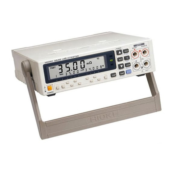
___________________________________________________________________ Chapter 1 Outline The 3540 mΩ HiTESTER is an four-terminal method tester designed to accurately measure the coil resistance in motors and transformers, the contact resistance of relays, switches and connectors, and the trace resistance on printed circuit boards. In addition, a temperature correction function, comparator function and data output function are provided, making the 3540 mΩ... - Page 16 ___________________________________________________________________ Ohmmeter Ohmmeter Constant current Constant current source source Voltmeter Voltmeter Resistance Resistance The current I flows to the measured All of the current I flows to the resistance R and the wiring measured resistance R resistance r and r Therefore, the voltage drop of r Therefore, the measuring voltage E become 0, and voltage E and the...
-
Page 17: Temperature Correction Function
___________________________________________________________________ 1.2 Temperature Correction Function The temperature sensor used in the 3540's temperature probe is a thin platinum film whose resistance changes according to temperature. The resistance of the film is detected and converted to a temperature value by the CPU. This section explains use of the 3540's temperature coefficient correction function. - Page 18 ___________________________________________________________________ For 3540 temperature correction, conductivity σ is calculated as 1. Accordingly, when the resistance value R that is displayed at , the measured the time of temperature correction is taken as R resistance at the current ambient temperature is expressed by the following expression.
-
Page 19: Effects Of Thermoelectromotive Force
___________________________________________________________________ 1.3 Effects of Thermoelectromotive Force Thermoelectromotive force is the potential difference at the junction of two dissimilar metals. If this emf is large, measurement errors can result. As the 3540 uses constant direct current flowing through the object being measured, readings can be affected by even slight thermoelectromotive force. - Page 20 ___________________________________________________________________ If the measurement error is large due to the effect of thermoelectromotive force, the following countermeasures can be employed. (1) Reverse the probes and use the average measured value. (2) As the thermoelectromotive force is temperature dependent, maintain a constant temperature in the measurement environment. ___________________________________________________________________ 1.3 Effects of Thermoelectromotive Force...
-
Page 21: Chapter 2 Name And Functions
___________________________________________________________________ Chapter 2 Name and Functions 2.1 Front Panel Input terminal Handle Comparator display keys 7.TC key(8.TEMP key) 4.AUTO key 5.HOLD key (6.0ADJ key) 9.LOCK key 15.HI/REF key 13.COMP key (UNLOCK key) 14.TABLE key 17.Buzzer key 12.SHIFT key 1.Power switch 10. - Page 22 ___________________________________________________________________ 1. POWER switch On power-up, the LCD and LED's light and the instrument performs an internal check and initialization of internal analog circuits. An error code is displayed if an internal error is detected during the check. (Refer to "8.4 Error Code Table".) Upon completion of the internal check, the LCD displays the instruments power supply frequency setting and the 3540 version number.
- Page 23 ___________________________________________________________________ 8. TEMP key Page 36 Pressing SHIFT + TEMP with the temperature probe connected selects the temperature measurement mode. Pressing SHIFT + TEMP a second time returns measurement to the resistance mode. 9. LOCK / UNLOCK key, LOCK mark Pressing the LOCK key lights the LOCK mark on the LCD and locks out key input.
- Page 24 ___________________________________________________________________ 15. HI/REF key, comparator mode display Page 31 The comparator mode is selected with the HI/REF key. When the HIGH or LOW mark is lit on the LCD, the comparator is in the Hi-Lo mode. When the REF or % mark is lit, it is in the REF-% mode.
-
Page 25: Rear Panel
___________________________________________________________________ 2.2 Rear Panel 2.2.1 3540 TC sensor jack (Page 36) 2. AC adapter jack 2.2.2 3540-01 External connector (Page 40) External terminal (Page 39) 1. AUTO/MANU selection switch TC sensor jack (Page 36) 2. AC adapter jack 2.2.3 3540-02 Printer connector (Page 73) External terminal (Page 39) 1. - Page 26 2. AC adapter jack The 3540 can be operated from an AC power source by connecting an AC adapter. When using an AC adapter, use only the specified HIOKI model 9445-02, 9445-03 AC ADAPTER (SA10-0910G, SINO- AMERICAN). An AC adapter rated at 9 VDC and 1.4 A to the AC adapter socket.
-
Page 27: Top Case
___________________________________________________________________ 2.3 Top Case Battery cover (Page 78) ___________________________________________________________________ 2.3 Top Case... - Page 28 ___________________________________________________________________ ___________________________________________________________________ 2.3 Top Case...
-
Page 29: Chapter 3 Specifications
___________________________________________________________________ Chapter 3 Specifications 3.1 General Specifications Measurement method Four-terminal method Operating method Dual integrator circuit Display LCD display Resistance measurement 3500 counts Temperature measurement 999 counts Auto range Provided (disabled when comparator is on) Input overflow "OF" display Current abnormality "----"... - Page 30 ___________________________________________________________________ Interface RS-232C interface Printer Centronics interface Power supply frequency 50/60 Hz, switchable Overvoltage protection 30 VDC or ACpeak (circuit protection by fuse) Operating 0 to 40 C (32 to 104 ), 80 %RH or less temperature/humidity (No condensing) Storage temperature/humidity -10 to 50 C (14 to 122 ), 80 %RH or less (No condensing)
- Page 31 ___________________________________________________________________ Accessories 9287-10 CLIP TYPE LEAD, 9451 TEMPERATURE PROBE, Instruction Manual, Six R6P manganese batteries, Spare fuse to protect the circuit (F1.0 AH/250 V), Ferrite Clamp (for AC adapter and temperature probe), External connector socket Options 9445-02 AC ADAPTER (SA10-0910N, SINO-AMERICAN) 9445-03 AC ADAPTER (SA10-0910G, SINO-AMERICAN) 9452 CLIP TYPE LEAD,...
-
Page 32: Measurement Range
___________________________________________________________________ 3.2 Measurement Range Measurement condition 23 5 ), 80 %RH or less (No condensing) After zero adjustment Pre-heating period 30 minutes Effect of radiated radio- At 3 V/m 30 dgt max. frequency electromagnetic field Resistance measurement (with sampling rate set to SLOW) 3 Ω... - Page 33 ___________________________________________________________________ Temperature measurement and temperature correction 6month Temperature correction accuracy Temperature (Add the following values to the Temperature range measurement accuracy accuracy specifications of the resistance measurement) -10.0 to 39.9 0.3 %rdg. 0.3 % (14.0 to 103.9 ) 40.0 to 99.9 0.3 %rdg.
- Page 34 ___________________________________________________________________ ___________________________________________________________________ 3.2 Measurement Range...
-
Page 35: Chapter 4 Operating Procedure
___________________________________________________________________ Chapter 4 Operating Procedure 4.1 Preparing Measurement The 3540 works on battery power or with an 9445-02, 9445-03 AC ADAPTER (SA10-0910G, SINO-AMERICAN). When using the AC adapter, fit the provided ferrite clamp over the adapter cable as shown in the figure. Refer to the section on battery replacement when installing batteries into the battery compartment while. -
Page 36: Measurement Leads
___________________________________________________________________ 4.1.1 Measurement Leads Connect the leads as shown in the following figure : The side with "v" mark is SENSE. SENSE SENSE SOURCE SOURCE SENSE SENSE SOURCE SOURCE Black Black When clipping a thin line When clipping a thick line (Clip the line at the deep, (Clip the line at the tip, serrated part of the jaws.) -
Page 37: About The Temperature Probe
___________________________________________________________________ 4.1.2 About the Temperature Probe When using the 9451 TEMPERATURE PROBE, loop the probe cable once around the provided ferrite clamp and fasten it as shown in the figure. 4.1.3 Instrument Handle When using the handle as a stand for the device, do not CAUTION press down too hard on the device as this can damage the handle. -
Page 38: Resistance Measurement
___________________________________________________________________ 4.2 Resistance Measurement (1) Plug the leads into the input terminals. Make the connection by mating the red marks on the leads. Make the connection by mating the black marks on the unit and the leads. (See the Figure below.) (2) Select the range. -
Page 39: Setting The Power Supply Frequency
___________________________________________________________________ 4.2.1 Setting the Power Supply Frequency To properly suppress noise, this product must be set to CAUTION match the power supply frequency. Before using the product, make sure the power supply frequency selector is set correctly, to avoid erroneous readings. First press the SHIFT key, then press 50/60Hz . -
Page 40: Changing The Measurement Range
___________________________________________________________________ 4.2.2 Changing the Measurement Range Manual range The measurement range is changed by pressing the key. Pressing the key cycles the range selection through the sequence from 30 mΩ, to 300 mΩ, and so forth up to 30 kΩ. Pressing the key cycles the range selection through the sequence from 30 kΩ, to 3 kΩ, and so forth down to 30 mΩ. -
Page 41: Zero Adjust Function
___________________________________________________________________ 4.2.3 Zero Adjust Function Zero adjustment is performed by shorting the test leads, then pressing first the SHIFT key, then the 0ADJ . (Zero adjustment is only possible with a reading of 100 counts or less.) Connect the test leads as shown below. The connection must be made exactly as shown;... -
Page 42: Switching The Sampling Speed
___________________________________________________________________ The zero adjust value is maintained internally even when the NOTE power is turned off. However, note that zero adjustment must be performed for each measurement range to be used. 4.2.4 Switching the Sampling Speed Pressing the SAMPL key toggles the sampling speed between two settings, FAST and SLOW. -
Page 43: Overload Indicator
___________________________________________________________________ 4.2.6 Overload Indicator If the input overloads, the following mark is displayed on the LCD. 4.2.7 Current Abnormality (CCERR) Detection Function If any abnormality is detected in the regularity of current in the power supply, the current abnormality detection circuit operates and the symbols indicating CCERR, as shown below, is displayed on the LCD to advise of current abnormality. -
Page 44: Comparator Function
___________________________________________________________________ 4.3 Comparator Function The 3540 allows storing of up to 7 comparator configuration tables. Each table can hold the comparator configuration for measurement range, comparator mode, buzzer and mode. The results of comparison are indicated by buzzer, as well as by lighting of the Hi, IN, and Lo LEDs. -
Page 45: Using The Comparator
___________________________________________________________________ 4.3.1 Using the Comparator Pressing the COMP key lights the comparator display on the LCD and starts the comparator function, allowing you to make comparative measurements Pressing the COMP key a second time turns off the comparator. 4.3.2 Selecting the Comparator Table The 3540 allows saving up to 7 tables of comparator configurations. -
Page 46: Selecting The Buzzer Mode
___________________________________________________________________ 4.3.4 Selecting the Buzzer Mode Pressing the buzzer key switches the buzzer mode of the currently displayed comparator table. Available buzzer modes are the HL mode, in which the buzzer sounds when comparison results are "Hi" or "Lo"; the IN mode, in which the buzzer sounds when the comparison result is "IN";... -
Page 47: Configuring The Comparison Values
___________________________________________________________________ 4.3.5 Configuring the Comparison Values With the Hi-Lo comparator The upper (HIGH) and lower (LOW) limit values are set using the comparator configuration keys. The configuration range in counts is from 0 to 9999. (A count is the number resulting after any decimal point and unit are eliminated from a numeric value With the REF-% comparator The reference value (REF) and range (%) are set using the... -
Page 48: Outputting Comparator Results
___________________________________________________________________ 4.3.6 Outputting Comparator Results Comparator results can be output using either of two modes: the auto mode or the manual mode. With the 3540-01, 3540-02 and 3540-03, the external control mode can be selected using the AUTO/MANU selector switch on the rear panel. -
Page 49: Temperature Correction Function (Tc)
___________________________________________________________________ 4.4 Temperature Correction Function (TC) This function uses the principle of temperature correction (refer to "1.2 Temperature Correction Function") to convert the resistance of copper wire to its 20 equivalent resistance. Connect the 9451 TEMPERATURE PROBE to the TC sensor jack on the rear panel. -
Page 50: Temperature Measurement
___________________________________________________________________ 4.5 Temperature Measurement Turn the power off. And connect the TC adapter as a following this Figure. Temperature probe TC sensor jack Plug into the TC sensor jack on the panel After turning on the power and pressing SHIFT followed by TEMP , ambient temperature is sensed by the temperature probe and displayed as follows. -
Page 51: Chapter 5 External Control Features
___________________________________________________________________ Chapter 5 External Control Features This chapter explains external control features of the 3540-01, 3540-02 and3540-03. The rear panel of the 3540-01 is equipped with external connectors (for BCD output, range and comparator control, etc.), and an external terminal strip (for trigger input, comparator output, and so forth). -
Page 52: Connectors
___________________________________________________________________ 5.1 Connectors The 3540-01, 3540-02 and 3540-03 are equipped with external connectors and/or terminals. Signals assigned to these terminals can be used to control operation of the 3540 or determine its status. Functions of the various terminals and procedures for using the corresponding signals are described below. -
Page 53: The External Terminal
___________________________________________________________________ 5.1.1 The External Terminal The External Terminal (3540-01 and 3540-03) INPUT OUTPUT The External Terminal (3540-02) INPUT OUTPUT Signals Input and output Signals Input and output Ground Power supply Open collector TRIG output MANU TTL input 0ADJ CCERR PRINT* * 3540-02 only ___________________________________________________________________ 5.1 Connectors... -
Page 54: The External Connectors
___________________________________________________________________ 5.1.2 The External Connectors : DCLC-J37SAF-13L9 (made by Japan aviation Using connector electron) 37 pins receptacle FDCD-37P (made by HIROSE) 37 pins plug Adaptive pin * A plug with FDCD-37P type compatible pins is provided with the 3540-01. For details on the compatible pins and use of the plug, refer to "5.2.2 External Connectors". -
Page 55: Connections To Terminals
___________________________________________________________________ 5.2 Connections to Terminals 5.2.1 The External Terminal (1) Use suitable wires bared at their ends for a length of about 10 mm. (2) As shown in Figure, depress the knob on the terminal with a screwdriver, and push the end of the wire into the connection hole. (3) Release the screwdriver, and the wires will be locked into place. -
Page 56: External Connectors
___________________________________________________________________ 5.2.2 External Connectors (1) Make connections to the compatible pins as appropriate for the pin assignments of the external connector. (2) Plug the connector wired in (1) firmly into the external connector. (3) Fasten the plug to the external connector with screws (M2.6). About the accessory plug The connector plug (FDCD-37P) provided with the 3540-01 is equipped with a flat cable pressure connector. -
Page 57: Electrical Specification
___________________________________________________________________ 5.3 Electrical Specification 5.3.1 Power Supply Rating Power supply (GND + Approx. 5 V) Approx. 200 mA max. Ground (0 V) The maximum capacity of this power supply is about 200 mA. NOTE In situations requiring more power, use an external power supply. If transitory current is required, insert an electrolytic capacitor between 5 V and GND. -
Page 58: Input/Output Ratings
___________________________________________________________________ 5.3.2 Input/output Ratings The ratings given here are absolute maximums. This WARNING means that exceeding these values, even momentarily, may result in damage to the circuits. Always ensure that applied voltage and current are below the rated values. However, with TTL output, never apply polarized voltage or current. -
Page 59: Internal Circuit
___________________________________________________________________ 5.3.3 Internal Circuit 4.7 KΩ 4.7 KΩ H-CMOS H-CMOS 22 Ω 22 Ω Output Input 0.1 µF TRIG, 0 ADJ, Protection protection PRINT only diode diode TTL input circuit TTL output circuit 10.5 kΩ Output 7.2 kΩ 3 kΩ Open corrector output circuit ___________________________________________________________________ 5.3 Electrical Specification... -
Page 60: Using The Signals
___________________________________________________________________ 5.4 Using the Signals This section explains how to use the 3540's various signals and shows the signals' timing charts. Since the timing charts indicate the logic of the signals, the high NOTE line positions are "valid" and the low line positions are "invalid." Note that the positions of the lines are not related to the signal (voltage) levels. -
Page 61: Measurement Control
___________________________________________________________________ 5.4.1 Measurement Control With measurement in the hold state In the hold state, measurement starts when TRIG becomes valid, then EOC becomes valid when measurement ends. EOC then remains valid until the next time TRIG becomes valid. TRIG Measurement Measurement 5 ms min. - Page 62 ___________________________________________________________________ Changing the measurement range The measurement range used by the 3540 change be changed using signals RANGE 0 to RANGE 2. RANGE 0 to 2 Range code a Range code b Range a Range b FAST: 400 ms max. SLOW: 550 ms max.
- Page 63 ___________________________________________________________________ Changing the Comparator Table The comparator table used by the 3540 can be changed using signals COMP 0 to COMP 2. COMP 0 to 2 Table code a Table code b Table a Table b FAST: 400 ms max. SLOW: 550 ms msx.
-
Page 64: Outputting Measurement Results
___________________________________________________________________ 5.4.2 Outputting Measurement Results Measurement output in the auto mode (outputting comparator results) In the auto mode, comparator results (Hi, IN, Lo) and result data of measurements (BCD, DP) are output when EOC becomes valid after measurement is completed. Comparator results and measurement data should be taken after EOC becomes valid (at the signal's rising edge). - Page 65 ___________________________________________________________________ Output during current abnormalities When a current abnormality occurs (when the resistance being measured is unchucked), the CCERR signal becomes valid. When this happens, the all comparator result output becomes invalid. CCERR Comparator result Measurement result Chucked Unchecked Chucked 1 ms max.
- Page 66 ___________________________________________________________________ Measurement DP 2 DP 1 DP 0 Exponent range 30 mΩ x 10 300 mΩ x 10 3 Ω x 10 30 Ω x 10 300 Ω x 10 3 kΩ x 10 30 kΩ x 10 Meanings of DP codes Measured values are expressed as follows by the BCD and DP codes.
-
Page 67: Chapter 6 Rs-232C Interface
___________________________________________________________________ Chapter 6 RS-232C Interface 6.1 Specifications 6.1.1 RS-232C Settings The RS-232C settings of the 3540-03 are as follows. Since the 3540 settings are fixed and cannot be changed, these settings must be matched on the computer side. Start-stop synchronization, full duplex Transmission mode: 9600 Transfer rate:... -
Page 68: Connector
___________________________________________________________________ 6.1.3 Connector Pin arrangement of interface connector (D-sub 9-Pin male) The signal lines of the 3540-03's RS-232C connector are as follows. Pin number Signal Contents Incoming data Outgoing data Signal ground Other pins are not used 6.1.4 Connection Method Use a cross cable for connecting to the computer. -
Page 69: Communication Method
___________________________________________________________________ 6.2 Communication Method 6.2.1 Connection to Computer Connect the 3540-03 to the computer using a cross cable. RS-232C cross cable 3540 Computer Perform the RS-232C settings on the computer side. For details on how to make the settings, refer to the instruction manual for the computer. -
Page 70: Command Format
___________________________________________________________________ 6.2.3 Command Format The 3540 commands have the following structure. Command + parameter + delimiter The command and the parameter are separated by " " (one character space). If there is no parameter, send the delimiter after the command. The command may consist of both upper and lower case letters. -
Page 71: Response Format
___________________________________________________________________ 6.2.4 Response Format When a command is sent to 3540, 3540 processes the command. When processing is completed, 3540 always returns a response. When there is no information from 3540, OK (+ delimiter) When there is information from 3540 (measurement values, etc.), Response character string related to the command (+ delimiter) When the command contained an error,... -
Page 72: Command
___________________________________________________________________ 6.3 Command 6.3.1 Explanation of Command References Syntax Describes the syntax of the command. <data> Explains the parameter data. Response Explains the received data. Function Explains the actions specified by the command. Error Describes errors that may occur when the command is executed. Example Command execution examples. -
Page 73: Command References
___________________________________________________________________ 6.3.2 Command References RESET Initializes the settings Syntax RESET Response Initialization completed Function Initializes the settings of the 3540 Measurement mode Resistance measurement mode Measurement range 30 mΩ range Sampling speed SLOW Hold function Free-running (hold state canceled) Comparator Comparator not used Table No. - Page 74 ___________________________________________________________________ TMES Temperature measurement value Syntax TMES Response <tdata> <data> <tdata> Temperature measurement value (See "6.3.3 Received Data".) Function Obtains the latest temperature measurement value Examples Obtaining temperature measurement values. PC >TMES Obtain measurement value. 3540 > 25.6? Temperature measurement value 25.6 PC >TMES Obtain measurement value 3540 >- 5.1?
- Page 75 ___________________________________________________________________ Resistance measurement end confirmation Syntax Response Resistance measurement completed Resistance measurement unfinished Function Checks whether the resistance measurement is completed. The condition of the measurement completed is cleared when the data is readout with this command. Example Checks whether the resistance measurement is completed. PC >EOC Checks whether the resistance measurement is completed.
- Page 76 ___________________________________________________________________ Zero-adjust Syntax Response Zero adjustment completed EXEC ERR Zero adjustment execution error Function Executes zero adjustment Error When attempts are made to perform zero adjustment with a reading exceeding 100 counts, the zero adjustment error is generated and zero adjustment is prevented. In these cases, the execution error is returned as the response.
- Page 77 ___________________________________________________________________ Range setting Syntax RNG <range data> <data> <func data> 0: 30.00 mΩ 1: 300.0 mΩ 2: 3.000 Ω 3: 30.00 Ω 4: 300.0 Ω 5: 3.000 kΩ 6: 30.00 kΩ Response Switch of range for resistance measurement completed. Function Sets the range to the specified resistance measurement range.
- Page 78 ___________________________________________________________________ Setting the power supply frequency Syntax HZ <hz data> <data> <func data> 0: 50 Hz 1: 60 Hz Response Setting of the power supply frequency completed. Function Sets the power supply frequency to 50 Hz or 60 Hz. Example Setting the power supply frequency to 50 Hz.
- Page 79 ___________________________________________________________________ AUTO Auto range Syntax AUTO <on/off> <data> <on/off> 0: OFF 1: ON Response Auto range setting completed. EXEC ERR Auto range setting execution error. Function Toggles the auto range ON or OFF. Error While the comparator is ON, auto range cannot be set to ON. If this is attempted, the response will indicate an execution error.
- Page 80 ___________________________________________________________________ COMP Comparator Syntax COMP <on/off> <data> <on/off> 0: OFF 1: ON Response Comparator ON/OFF setting completed. Function Toggles the comparator ON or OFF. Example Turning ON the comparator. PC >COMP 1 Set comparator to ON. 3540 >OK Setting completed. Comparator table Syntax CNO <comp no>...
- Page 81 ___________________________________________________________________ Comparator mode setting Syntax CMD <comp mode> <data> <comp mode> 0: Hi-Lo 1: REF-% Response Comparator mode setting completed. EXEC ERR Execution error Function Sets the comparator mode to Hi-Lo or REF-%. Error When the comparator is not ON, this setting is not possible. If attempted, the execution error is generated.
- Page 82 ___________________________________________________________________ Comparator HIGH/REF setting Syntax CHI <comp hi data> <data> <comp hi data> 0 to 9999: Upper limit value (HIGH) or reference value (REF) (Count value with the decimal point neglected.) Response Comparator HIGH/REF data setting completed. EXEC ERR Execution error Function Sets the comparator HIGH and REF setting values to the specified values.
- Page 83 ___________________________________________________________________ Constant-current status check Syntax Response Constant-current normal CC OK Constant-current abnormality (CCERR) CC ERR Function Checks the condition of the current for resistance measurement. Unless the constant-current flows correctly, the resistance value cannot be measured. Examples Checking the current constant-current status. PC >CCC Find the constant-current status.
-
Page 84: Received Data
___________________________________________________________________ 6.3.3 Received Data <rdata> The rdata format of the resistance measurement value data is as follows. measurement value + "," + comparator results When the comparator is OFF, the format only consists of the measurement value and the "," + comparator results are not attached. - Page 85 ___________________________________________________________________ Comparator results Comparator results are indicated by single digits as follows: 0: Invalid 1: Lo 2: IN 3: Hi Examples 35.00E-03 35.00 mΩ 3.500 Ω 3.500E+00 35.00 Ω, comparator result = Lo. 35.00E+00,1 3.500E+03,2 3.500 kΩ, comparator result = IN. 100.5,3 100.5 %, comparator result = Hi.
- Page 86 ___________________________________________________________________ ___________________________________________________________________ 6.3 Command...
-
Page 87: Chapter 7 Printers
___________________________________________________________________ Chapter 7 Printers This chapter discusses printer output from the 3540-02. With the 3540-02, measured values can be printed out using the optional 9203 DIGITAL PRINTER or other general purpose Centronics printer. This instruction manual explains how to print out measured values to a general purpose Centronics printer. - Page 88 ___________________________________________________________________ To printer Always observe the following safety precautions WARNING when connecting a printer. Failure to observe these safety precautions may result in electrocution or damage to the equipment. Always turn off the product and the printer before making any connections. Because of the inherent dangers of such situations, be careful to prevent the connections from coming loose or leads from coming into contact with other...
-
Page 89: Printing
___________________________________________________________________ 7.2 Printing This section explains printing to a general purpose Centronics printer. For printing using the 9203, refer to the 9203 Instruction Manual. A printout example is shown below, along with the meanings of the printed data. Measurement measured Function Comparator range... - Page 90 ___________________________________________________________________ ___________________________________________________________________ 7.2 Printing...
-
Page 91: Chapter 8 Maintenance And Service
___________________________________________________________________ Chapter 8 Maintenance and Service 8.1 Battery Replacement Procedure To avoid electric shock when replacing the batteries WARNING first disconnect the AC adapter and leads from the object to be measured. Also, after replacing the batteries always replace the cover before using the unit. - Page 92 ___________________________________________________________________ The battery mark on the LCD lights when the battery is exhausted. When this occurs, change the battery as follows. (1) Remove the battery cover (2) Replace the batteries with new ones, observing the correct polarity. (3) Replace the battery cover. Battery cover R6P manganese batteries or LR6 alkaline batteries...
-
Page 93: Fuse Replacement Procedure
___________________________________________________________________ 8.2 Fuse Replacement Procedure To avoid danger of electrical shock when changing WARNING the fuse, disconnect the AC adapter and all test leads and other wiring from the 3540 before making replacement. After replacing the fuse, be sure to close the case before using the instrument. -
Page 94: Troubleshooting
___________________________________________________________________ 8.3 Troubleshooting When the instrument does not work normally, check the following items : Symptom Cause/remedy LCD does not light Is the correct AC adaptor being used, and is it properly when POWER connected? switch pressed. Refer to "4.1 Preparing Measurement". Is the battery exhausted? Refer to "8.1 Battery Replacement Procedure". - Page 95 ___________________________________________________________________ Symptom Cause/remedy Cannot output to Is the PRINT signal wired properly? printer. Refer to "Chapter 5 External Control Features". Is the printer properly connected? Refer to "Chapter 7 Printers". RS-232C Has the RS-232C cable been connected correctly? communication not Are the settings on the computer correct? possible.
-
Page 96: Error Code Table
___________________________________________________________________ 8.4 Error Code Table An error code is displayed on the LCD when particular errors occur. Example: Error code Meaning Zero-adjust range (within 100 display counts) exceeded Temperature probe not properly connected while using temperature correction functions. Attempted to print while printer not properly connected. -
Page 97: Service
When sending the product for repair, remove the batteries and pack carefully to prevent damage in transit. Include cushioning material so the instrument cannot move within the package. Be sure to include details of the problem. Hioki cannot be responsible for damage that occurs during shipment. 8.6 Cleaning To clean the product, wipe it gently with a soft cloth moistened with water or mild detergent. - Page 98 ___________________________________________________________________ ___________________________________________________________________ 8.6 Cleaning...
- Page 101 HIOKI 3540 mΩ HiTESTER Instruction Manual Publication date: September 2006 Revised edition 13 Edited and published by HIOKI E.E. CORPORATION Technical Support Section All inquiries to International Sales and Marketing Department 81 Koizumi, Ueda, Nagano, 386-1192, Japan TEL: +81-268-28-0562 / FAX: +81-268-28-0568 E-mail: os-com@hioki.co.jp...
- Page 102 2003-01 改訂 枠消す HEAD OFFICE 81 Koizumi, Ueda, Nagano 386-1192, Japan TEL +81-268-28-0562 / FAX +81-268-28-0568 E-mail: os-com@hioki.co.jp / URL http://www.hioki.co.jp/ HIOKI USA CORPORATION 6 Corporate Drive, Cranbury, NJ 08512, USA TEL +1-609-409-9109 / FAX +1-609-409-9108 3540A981-13 06-09H Printed on recycled paper...
Need help?
Do you have a question about the HiTESTER 3540 and is the answer not in the manual?
Questions and answers