
Related Manuals for Hioki 3555


Summary of Contents for Hioki 3555
- Page 1 INSTRUCTION MANUAL For...は専用機種。複数の場合は「/」で区切る。 不要の場合はとる。 形名を入力。 複数の場合は「/」で区切る。 3555 品名を入力。 BATTERY HiTESTER http://www.911618.com/ http://www.911618.com/dianchiceshiyi/HIOKI-3555/ http://www.911618.com/jishuwenzhang/HIOKI-3555/...
-
Page 2: Table Of Contents
Contents Introduction Inspection Safety Precautions Organization of This Manual viii Chapter 1 Overview 1.1 Product Overview 1.2 Features Chapter 2 Names and Functions of Parts Chapter 3 Specifications 3.1 General Specification 3.2 Measurement Range 3.2.1 Maximum Input Voltage 3.2.2 Dielectric Strength Chapter 4 Standard Measurement 4.1 Preparing for Measurement 4.2 Measurement... - Page 3 5.3 Hold Function 5.4 Zero Adjust Function 5.5 Battery Low Warning 5.6 Auto Power Off 5.7 AC Four-Terminal Method Chapter 6 Maintenance 6.1 Troubleshooting 6.2 Message Reference 6.3 Cleaning...
-
Page 4: Introduction
―――――――――――――――――――――――――――――――――――――― Introduction Thank you for purchasing the HIOKI "3555 BATTERY HiTESTER." To obtain maximum performance from the instrument, please read this manual first, and keep it handy for future reference. Inspection When you receive the instrument, inspect it carefully to ensure that no damage occurred during shipping. -
Page 5: Safety
―――――――――――――――――――――――――――――――――――――― Safety This instrument is designed to comply with IEC 61010 DANGER Safety Standards, and has been thoroughly tested for safety prior to shipment. However, mishandling during use could result in injury or death, as well as damage to the instrument. Be certain that you understand the instructions and precautions in the manual before use. - Page 6 ―――――――――――――――――――――――――――――――――――――― The following symbols in this manual indicate the relative importance of cautions and warnings. Indicates that incorrect operation presents an extreme hazard that could result in serious DANGER injury or death to the user. Indicates that incorrect operation presents a WARNING significant hazard that could result in serious injury or death to the user.
- Page 7 ―――――――――――――――――――――――――――――――――――――― Measurement categories (Overvoltage categories) This instrument complies with CAT I safety requirements. To ensure safe operation of measurement instruments, IEC 61010 establishes safety standards for various electrical environments, categorized as CAT I to CAT IV, and called measurement categories. These are defined as follows. CAT I : Secondary electrical circuits connected to an AC electrical outlet through a transformer or similar...
-
Page 8: Precautions
Using the instrument in such conditions could cause an electric shock, so contact your dealer or Hioki representative for replacements (Model 9461, Model 9287-10). ――――――――――――――――――――――――――――――――――... - Page 9 ―――――――――――――――――――――――――――――――――――――― Be sure to connect the SOURCE and SENSE terminals WARNING correctly. See Section 4.2, "Measurement" for details of the connections. To avoid injury or damage to the instrument, do not attempt to measure AC voltage, or DC voltage exceeding 50 V. 50 VDC max Do not apply a voltage between the SOURCE(+) and SENSE(+) or SOURCE(-) and SENSE(-) terminals.
- Page 10 Include cushioning material so the instrument cannot move within the package. Be sure to include details of the problem. Hioki cannot be responsible for damage that occurs during shipment. ―――――――――――――――――――――――――――――――――― Precautions...
-
Page 11: Organization Of This Manual
viii ―――――――――――――――――――――――――――――――――――――― Organization of This Manual This manual consists of the following chapters. "Introduction", "Inspection", "Safety", "Precautions" include some important notes which you should read before using the instrument. Chapter 1 Overview describes an outline of the instrument, and lists its features. -
Page 12: Chapter 1 Overview
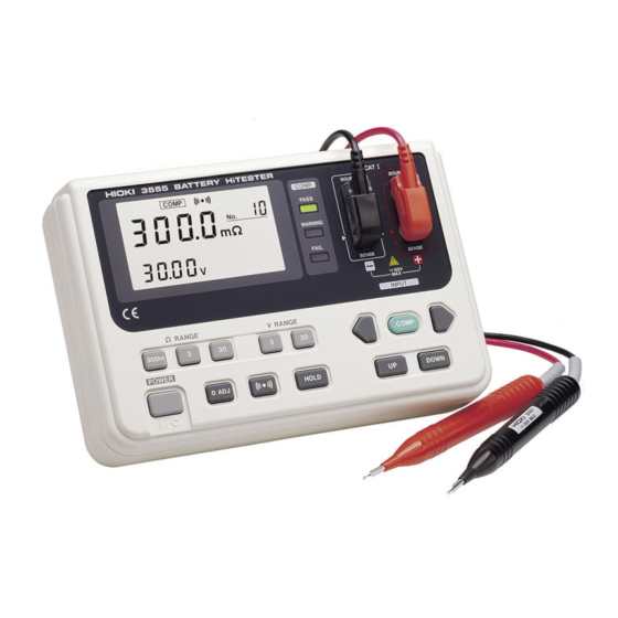
―――――――――――――――――――――――――――――――――――――― Chapter 1 Overview 1.1 Product Overview The 3555 is designed for measuring the internal resistance and open-circuit voltage of secondary batteries, including lead storage cells, nickel-cadmium batteries, nickel-metal hydride batteries, and lithium-ion batteries. 1.2 Features (1) Since it uses the AC four-terminal method to measure the internal resistance, it provides accurate results with the lead resistances and contact resistances eliminated. - Page 13 ―――――――――――――――――――――――――――――――――――――― ―――――――――――――――――――――――――――――――――― Chapter 1 Overview...
-
Page 14: Chapter 2 Names And Functions Of Parts
―――――――――――――――――――――――――――――――――――――― Chapter 2 Names and Functions of Parts This chapter explains the keys, input and output terminals, display, LED indicators, and leads. ―――――――――――――――――――――――――――――――――― Chapter 2 Names and Functions of Parts... - Page 15 ―――――――――――――――――――――――――――――――――――――― Front panel Side panel ―――――――――――――――――――――――――――――――――― Chapter 2 Names and Functions of Parts...
- Page 16 ―――――――――――――――――――――――――――――――――――――― Keys and input/output terminals Turns the power on or off. POWER Ω key 300m Ω key Selects the resistance range. Ω key V key Selects the voltage range. V key Zero adjustment key 0 ADJ Turns the beeper on and off. Locks out changes to the display.
- Page 17 ―――――――――――――――――――――――――――――――――――――― (view with all elements displayed) Display Measured resistance Measured voltage [comparator resistance upper limit setting and comparator voltage setting] [Comparator resistance lower limit setting] [ ]: Appears in on the comparator setting screen Indicates the unit of resistance. mΩ Indicates the unit of voltage.
- Page 18 ―――――――――――――――――――――――――――――――――――――― Appears during display of the screen for setting the comparator resistance upper and lower limit values. Appears during display of the screen for VOLT setting the comparator voltage threshold value. LEDs Indicates that the tested battery is PASS satisfactory for operation. Indicates that the tested battery is WARNING beginning to deteriorate.
- Page 19 9461 PIN TYPE LEAD Probe (red) Banana plug (red) Probe (black) Banana plug (black) SOURCE SENSE The ends of the 9461 PIN TYPE LEAD are sharp. Be CAUTION careful to avoid injury. http://www.911618.com/ http://www.911618.com/dianchiceshiyi/HIOKI-3555/ http://www.911618.com/jishuwenzhang/HIOKI-3555/ ―――――――――――――――――――――――――――――――――― Chapter 2 Names and Functions of Parts...
-
Page 20: Chapter 3 Specifications
―――――――――――――――――――――――――――――――――――――― Chapter 3 Specifications 3.1 General Specification Resistance: AC four-terminal Measurement method ■ method Double integration method A/D conversion ■ Display LCD and LEDs (comparator ■ output) , Ω, Panel abbreviations ■ HOLD COMP No. and symbols COMP.SET VOLT Sampling rate 1.25 sets (resistance and voltage ■... - Page 21 ―――――――――――――――――――――――――――――――――――――― Resistance upper and lower limits Comparator settings ■ and voltage lower limit Number of comparator Ten sets ■ settings LEDs for pass (green), warning Comparator output ■ (amber), and fail (red) results Audible tone for warning and fail results Resistance Voltage WARNING...
- Page 22 ―――――――――――――――――――――――――――――――――――――― Effect of radiated at 3V/m ■ Resistance measurement radio-frequency electromagnetic field ±3.0%f.s. Voltage measurement ±3.0% f.s. Standards applying ■ EN61326 :1997+A1:1998+A2:2001 +A3:2003 Safety EN61010-1:2001 Pollution Degree 1, Measurement Category I (anticipated transient overvoltage330 V) 9461 PIN TYPE LEAD Accessories ■...
-
Page 23: Measurement Range
―――――――――――――――――――――――――――――――――――――― 3.2 Measurement Range Conditions to guarantee accuracy: ・ Temperature 23℃±5℃ ・ Humidity 80% RH or less (no condensation) ・ Zero adjustment After zero adjustment for each range ・ Warming up time At least 10 minutes ・ Period of guaranteed accuracy 1 year (1) Resistance Measurement Temperature coefficient: (±0.01% rdg.±0.5 dgt.)/℃... -
Page 24: Maximum Input Voltage
―――――――――――――――――――――――――――――――――――――― 3.2.1 Maximum Input Voltage The maximum input voltage is 50V DC. Attempting DANGER to measure voltage in excess of the maximum input could destroy the instrument and result in personal injury or death. To avoid electrical hazards and damage to the instrument, do not apply voltage exceeding the maximum input to the measurement terminals. -
Page 25: Dielectric Strength
―――――――――――――――――――――――――――――――――――――― 3.2.2 Dielectric Strength Between input terminals and case: DANGER 350 V rms for 1 minute. 350 Vrms max for 1 minute http://www.911618.com/ http://www.911618.com/dianchiceshiyi/HIOKI-3555/ http://www.911618.com/jishuwenzhang/HIOKI-3555/ ―――――――――――――――――――――――――――――――――― Chapter 3 Specifications... -
Page 26: Chapter 4 Standard Measurement
―――――――――――――――――――――――――――――――――――――― Chapter 4 Standard Measurement 4.1 Preparing for Measurement To avoid electric shock when replacing the WARNING batteries, first disconnect the test leads from the object to be measured. Do not mix old and new batteries, or different types of batteries. Also, be careful to observe battery polarity during installation. -
Page 27: Measurement
―――――――――――――――――――――――――――――――――――――― To avoid the possibility of explosion, do not short WARNING circuit, disassemble or incinerate batteries. Handle and dispose of batteries in accordance with local regulations. ・ The " " indicator appears when battery voltage becomes NOTE low. Replace the batteries as soon as possible. ・... - Page 28 ―――――――――――――――――――――――――――――――――――――― ・ Do not attempt to measure the voltage of a generator. CAUTION This would result in an AC voltage being applied to the voltage-generating output terminals, which is dangerous. ・ After measuring a high-voltage battery, before continuing to measure a low-voltage battery first short the test leads together.
- Page 29 ―――――――――――――――――――――――――――――――――――――― 3. Contact the red probe of the 9461 with the positive battery terminal, and the black probe with the negative terminal. Battery Black As shown in the figure below, the outer shield conductors of the leads are connected to the SOURCE terminals, and the inner pin conductors are connected to the SENSE terminals.
- Page 30 ―――――――――――――――――――――――――――――――――――――― 4. Using the range keys, select the voltage and resistance measurement ranges. 5. When the measurement is completed, disconnect the leads from the tested battery and press the key to turn POWER off the power. ・ When measuring the contact resistance of a relay or NOTE connector, be careful of the open-circuit voltage across the test leads.
- Page 31 ―――――――――――――――――――――――――――――――――――――― ・ A resistance indication "----" means that the measurement could not be made because there is a break in the test lead circuit. The "----" indication may also appear if the leads are not making good contact with the object to be measured, or if its resistance is extremely large compared with the measurement range.
-
Page 32: Chapter 5 Advanced Measurement Functions
―――――――――――――――――――――――――――――――――――――― Chapter 5 Advanced Measurement Functions 5.1 Comparator Function 5.1.1 What is the Comparator Function? The comparator function compares the measurement values with preset lower and upper limit values for internal resistance and voltage level, and determines which range the measurement falls into, based on the following conditions. -
Page 33: Changing The Comparator Settings
―――――――――――――――――――――――――――――――――――――― 5.1.2 Changing the Comparator Settings (1) Before changing the settings To change the comparator settings (upper and lower resistance limits and voltage comparison value), do the following: 1. Press and hold the key for at least 3 seconds. The COMP upper and lower resistance limit settings appear. - Page 34 ―――――――――――――――――――――――――――――――――――――― (2) Setting the comparator number When the comparator setting screen appears, set the comparator number corresponding to the battery to be tested. 1. Using the keys, move the flashing number to the comparator number at the upper right of the screen. 2.
- Page 35 ―――――――――――――――――――――――――――――――――――――― (4) Setting the resistance limits 1. Using the key, move the flashing number to the most significant digit of the lower resistance limit setting at the lower left of the screen. Lower resistance limit Upper resistance limit 2. Set the lower and upper resistance limits with the keys.
- Page 36 ―――――――――――――――――――――――――――――――――――――― (5) Setting the voltage range 1. Using the key, move the flashing number to the least significant digit of the upper resistance limit setting at the lower right of the screen. 2. Press the key again to display the voltage comparison value setting screen will appear.
- Page 37 ―――――――――――――――――――――――――――――――――――――― (6) Setting the voltage comparison value 1. Using the key and the keys, set the DOWN voltage comparison value at the lower left of the screen. The allowable range of settings for the voltage comparison value is -3000 to 3000. Voltage range 2.
-
Page 38: Comparator Decision Result Table
―――――――――――――――――――――――――――――――――――――― 5.1.3 Comparator Decision Result Table The decision result is indicated by the LEDs and by the beeper, as shown in the following table. Resistance Lower resistance limit Upper resistance limit Voltage WARNING WARNING FAIL Voltage Amber *1 Amber comparison PASS WARNING FAIL... -
Page 39: Switching The Comparator On And Off
―――――――――――――――――――――――――――――――――――――― 5.1.4 Switching the Comparator On and Off ・ Pressing the key toggles the comparator function COMP on and off. When the comparator is on, the " " COMP indication appears in the display, and the comparator operates as measurements are taken. When the comparator is off, the "... -
Page 40: Changing The Comparator Number
―――――――――――――――――――――――――――――――――――――― 5.1.5 Changing the Comparator Number To change the comparator number, press the key. DOWN ・ When the comparator number is changed, the range is NOTE also automatically changed and comparator is set to on. ・ The selected comparator number remains in memory even when the power is turned off. -
Page 41: Hold Function
―――――――――――――――――――――――――――――――――――――― 5.3 Hold Function This suspends measurement, with the display values held the same. Press the key. " " is displayed on the screen HOLD HOLD and the display is locked to prevent it from changing. While the display is locked, the resistance and voltage NOTE Ω, Ω,... - Page 42 ―――――――――――――――――――――――――――――――――――――― 2. Press the key. During zero adjustment, "0Adj" is 0 ADJ displayed in the resistance measurement display position. 3. When "0Adj" disappears and measurement starts, connect the leads to the battery to be tested. ・ Keep the leads shorted together throughout the zero NOTE adjustment process.
-
Page 43: Battery Low Warning
―――――――――――――――――――――――――――――――――――――― 5.5 Battery Low Warning When the remaining battery capacity is low, the " " indicator appears at the right of the display. After printing out any held data values, replace the battery, referring to Section 4.1, "Preparing for Measurement." If the batteries are exhausted, you may be able to turn on NOTE the power, but soon the "... -
Page 44: Auto Power Off
―――――――――――――――――――――――――――――――――――――― 5.6 Auto Power Off In the following states, if there is no switch operation for 30 minutes the instrument automatically powers off. ・ When the resistance value is "----" indication. ・ During hold ・ On the comparator setting screen For continuous measurement, in some cases it may be necessary to disable the auto power off function. - Page 45 ・ After the batteries are replaced, the auto power off is set to 30 minutes. ・ The set time of auto power off cannot be changed. http://www.911618.com/ http://www.911618.com/dianchiceshiyi/HIOKI-3555/ http://www.911618.com/jishuwenzhang/HIOKI-3555/ ―――――――――――――――――――――――――――――――――― Chapter 5 Advanced Measurement Functions...
-
Page 46: Ac Four-Terminal Method
―――――――――――――――――――――――――――――――――――――― 5.7 AC Four-Terminal Method The 3555 uses the AC four-terminal method, so that resistance measurement can be carried out with the resistance of the leads and the contact resistance between the object to be measured and the leads canceled out. - Page 47 ―――――――――――――――――――――――――――――――――――――― In the 3555, a synchronized wave detection system is NOTE used, whereby the internal impedance is separated into resistance and reactance, and the resistive component only displayed. http://www.911618.com/ http://www.911618.com/dianchiceshiyi/HIOKI-3555/ http://www.911618.com/jishuwenzhang/HIOKI-3555/ ―――――――――――――――――――――――――――――――――― Chapter 5 Advanced Measurement Functions...
-
Page 48: Chapter 6 Maintenance
―――――――――――――――――――――――――――――――――――――― Chapter 6 Maintenance If damage is suspected, check the "Troubleshooting" section before contacting your dealer or Hioki representative. 6.1 Troubleshooting Symptom Cause Follow-up Nothing appears on Batteries are Replace the batteries or the screen when the exhausted, or not reinsert them correctly. -
Page 49: Message Reference
・ Never modify the instrument. Only a Hioki service engineer can disassemble or repair the instrument. Failure to observe these precautions may result in fire, electric shock, or injury. -
Page 50: Cleaning
―――――――――――――――――――――――――――――――――――――― 6.3 Cleaning ・ To clean the instrument, wipe it gently with a soft cloth moistened with water or mild detergent. Never use solvents such as benzene, alcohol, acetone, ether, ketones, thinners or gasoline, as they can deform and discolor the case. - Page 51 ―――――――――――――――――――――――――――――――――――――― ―――――――――――――――――――――――――――――――――― Chapter 6 Maintenance...
- Page 54 HIOKI 3555 BATTERY HiTESTER Instruction Manual Publication date: September 2006 Revised edition 8 Edited and published by HIOKI E.E. CORPORATION Technical Support Section All inquiries to International Sales and Marketing Department 81 Koizumi, Ueda, Nagano, 386-1192, Japan TEL: +81-268-28-0562 / FAX: +81-268-28-0568 http://www.911618.com/...
- Page 55 3555A981-08 06-09 Printed on recycled paper...
Need help?
Do you have a question about the 3555 and is the answer not in the manual?
Questions and answers