
Related Manuals for Hioki 3285-20


Summary of Contents for Hioki 3285-20
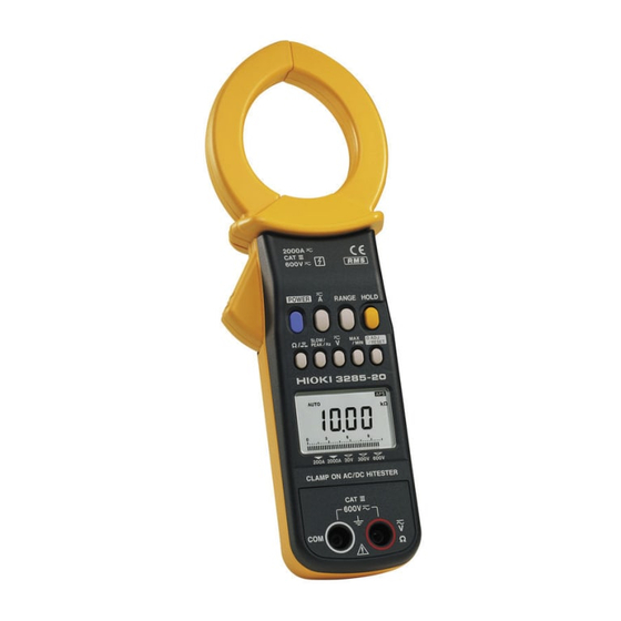
- Page 1 Instruction Manual 3285-20 CLAMP ON AC/DC HiTESTER December 2014 Revised edition 10 3285B981-10 14-12H...
-
Page 2: Table Of Contents
Contents Introduction Verifying Package Contents Safety Information Operating Precautions viii Preliminary Check Chapter 1 Overview 1.1 Product Overview 1.2 Features 1.3 Names and Functions of Parts 1.4 Flowchart of button Operations 1.4.1 Current Measurements Mode 1.4.2 Voltage Measurements Mode 1.4.3 Frequency Measurements Mode 1.4.4 Resistance Measurements Mode 1.5 Modes Chapter 2 Measurement... - Page 3 2.2 Current Measurement 2.2.1 Measuring DC Current (DC A) 2.2.2 Measuring AC Current (AC A) 2.2.3 Measuring AC/DC Current (AC+DC A) 2.2.4 Peak Hold Measurement 2.3 Voltage Measurement 2.3.1 Measuring DC Voltage (DC V) 2.3.2 Measuring AC Voltage (AC V) 2.3.3 Measuring AC/DC Voltage (AC+DC V) 2.3.4 Peak Hold Measurement 2.4 Frequency Measurement...
- Page 4 Chapter 4 Specifications 4.1 Measurement Specifications 4.1.1 Current Measurement Specifications 4.1.2 Voltage Measurement Specifications 4.1.3 Resistance Measurement Specifications 4.1.4 Continuity Check 4.2 General Specifications Chapter 5 Maintenanceand Service 5.1 Cleaning 5.2 After service 5.3 Troubleshooting 5.4 Error Massage...
-
Page 6: Introduction
We have tried to bring this manual as close to perfection as we could achieve. If perchance you find any unclear portions, mistakes, omissions, or the like, we would be most obliged if you could please notify us of them via any HIOKI agent, or directly. ___________________________________________________ Introduction... -
Page 7: Verifying Package Contents
If damage is evident, or if it fails to operate according to the specifications, contact your dealer or Hioki representative. Main unit 3285-20 Clamp-on AC/DC HiTester Supplied accessories 9345 Carrying Case L9207-10 Test Lead (red and black) Hand Strap... -
Page 8: Safety Information
___________________________________________________ Safety Information DANGER This instrument is designed to comply with IEC 61010 Safety Standards, and has been thoroughly tested for safety prior to shipment. However, mishandling during use could result in injury or death, as well as damage to the instrument. Be certain that you understand the instructions and precautions in the manual before use. - Page 9 ___________________________________________________ Safety Symbols symbol printed on the instrument indicates that the user should refer to a corresponding topic in the manual (marked with symbol) before using the relevant function. In the manual, the symbol indicates particularly important information that the user should read before using the instrument.
- Page 10 ___________________________________________________ The following symbols in this manual indicate the relative importance of cautions and warnings. Indicates that incorrect operation presents extreme danger of accident resulting in DANGER death or serious injury to the user. Indicates that incorrect operation presents a significant hazard that could result in WARNING serious injury or death to the user.
- Page 11 ___________________________________________________ Measurement categories This instrument complies with CAT III safety requirements. To ensure safe operation of measurement instruments, IEC 61010 establishes safety standards for various electrical environments, categorized as CAT II to CAT IV, and called measurement categories. These are defined as follows. Primary electrical circuits in equipment CAT II connected to an AC electrical outlet by a...
- Page 12 ___________________________________________________ ___________________________________________________ Safety Information...
-
Page 13: Operating Precautions
___________________________________________________ viii Operating Precautions Follow these precautions to ensure safe operation and to obtain the full benefits of the various functions. DANGER To avoid short circuits and potentially life- threatening hazards, never attach the clamp to a circuit that operates at more than 600 Vrms. The maximum rated voltage to earth is 600 Vrms. - Page 14 ___________________________________________________ WARNING Do not allow the instrument to get wet, and do not take measurements with wet hands. This may cause an electric shock. To avoid electric shock when measuring live lines, wear appropriate protective gear, such as insulated rubber gloves, boots and a safety helmet.
- Page 15 x ___________________________________________________ WARNING To prevent electric shock, when measuring the voltage of a power line use a test lead that satisfies the following criteria: Conforms to safety standards IEC61010 or EN61010 Of measurement category III or IV Its rated voltage is higher than the voltage to be measured The test leads provided with this instrument conform to the safety standard EN61010.
- Page 16 ___________________________________________________ CAUTION Do not store or use the instrument where it could be exposed to direct sunlight, high temperature or humidity, or condensation. Under such conditions, the instrument may be damaged and insulation may deteriorate so that it no longer meets specifications.
- Page 17 ___________________________________________________ CAUTION To avoid damage to the instrument, protect it from physical shock when transporting and handling. Be especially careful to avoid physical shock from dropping. Do not exert excessive pressure on the clamp sensor or attempt to wedge the sensor into a tight spot for measurement.
- Page 18 ___________________________________________________ xiii CAUTION Removable sleeves are attached to the metal pins at the ends of the test leads. To prevent a short circuit accident, be sure to use the test leads with the sleeves attached when performing measurements in the CAT III measurement category.
- Page 19 ___________________________________________________ Correct measurement may be impossible in the NOTE presence of strong magnetic fields, such as near transformers and high-current conductors, or in the presence of strong electromagnetic fields such as near radio transmitters. To avoid corrosion from battery leakage, remove the batteries from the instrument if it is to be stored for a long time.
-
Page 20: Preliminary Check
Using the instrument in such conditions could cause an electric shock, so contact your dealer or Hioki representative for replacements. (Model L9207-10 Test Lead). ___________________________________________________ Preliminary Check... - Page 21 ___________________________________________________ ___________________________________________________ Preliminary Check...
-
Page 22: Chapter 1 Overview
_______________________________________________________ Chapter 1 Overview 1.1 Product Overview The 3285-20 Clamp-on AC/DC HiTester makes it possible to measure DC, AC or AC+DC current in live power lines without tapping into or connecting the lines. And it is also possible to measure voltage, frequency and resistance, and check circuit continuity. -
Page 23: Features
2 _______________________________________________________ 1.2 Features Large current measurement Allows measurement of large current up to 2000 A. Display of true rms values The true rms value conversion circuit allows accurate measurement of currents with distorted waveforms. Measurement for AC/DC The instrument permits measurement of AC superimposed on DC, as well as measurement of half- and full-wave rectification. -
Page 24: Names And Functions Of Parts
_______________________________________________________ 1.3 Names and Functions of Parts 3285-20 _______________________________________________________ 1.3 Names and Functions of Parts... - Page 25 4 _______________________________________________________ POWER Used to turn power on/off To disable the auto power-off function, hold HOLD and press , when you turn power on. POWER button Switches current modes as follow. AC+DCA button RANGE Switches between auto and manual ranges in measurements of current, voltage, or frequency.
- Page 26 _______________________________________________________ Ω / button Switches between resistance measurement and continuity checking. Ω button SLOW/PEAK/Hz SLOW slows down screen updating speed (once per three seconds). FAST speeds up screen updating speed (four times per second). There isn't an annunciator " ". FAST Instead, the unit symbol blinks.
- Page 27 6 _______________________________________________________ 0ADJ/RESET Performs auto-zero-adjustment in DC A, AC+DC A and DC V modes. Resets data when measuring peak values. Reset all the data in a REC function. If zero is not indicated under no input in the AC A, AC+DC A, AC V or AC+DC V modes, press , then press to perform a zero-...
- Page 28 _______________________________________________________ 13 Display (LCD) Direct Current (DC) Alternating Current (AC) Alternating Current and Direct Current (AC+DC) Auto-zero-adjustment or zero- cancel correction function is active Battery low warning Data hold function HOLD Auto power off function AUTO Auto-range Counter update once every 3 SLOW seconds Record function...
- Page 29 8 _______________________________________________________ Ω Resistance Continuity Frequency Voltage PEAK Wave peak value True root mean square value Current hour 1 hour/segment (bar graph) 1 minute/segment (bar graph) Input over (bar graph) 14 Voltage/resistance input terminal (V, Ω, and COM terminals) Connected to the L9207-10 Test Lead (red and black, supplied with the instrument) to measure voltage or resistance.
- Page 30 _______________________________________________________ L9207-10 TEST LEAD 1 Protective barrier Be careful to not touch the metal part of the test lead beyond the safety barrier when contacting a conductor for measurement. 2 Sleeve Attach to the pins to prevent short circuit accidents. CAUTION B e sure to use the test leads with the sleeves ・...
-
Page 31: Flowchart Of Button Operations
_______________________________________________________ 1.4 Flowchart of button Operations 1.4.1 Current Measurements Mode button AC+DCA RANGE button AUTO range AUTO range AUTO range 200.0 A range 200.0 A range 200.0 A range 2000 A range 2000 A range 2000 A range SLOW/PEAK/Hz SLOW SLOW SLOW button... -
Page 32: Voltage Measurements Mode
_______________________________________________________ 1.4.2 Voltage Measurements Mode button DC V AC V AC+DC V RANGE button AUTO range AUTO range AUTO range 30.00 V range 30.00 V range 30.00 V range 300.0 V range 300.0 V range 300.0 V range 600 V range 600 V range 600 V range SLOW/PEAK/Hz... -
Page 33: Frequency Measurements Mode
_______________________________________________________ 1.4.3 Frequency Measurements Mode Current (AC A, AC+DC A) mode Voltage (AC V, AC+DC V) mode SLOW/PEAK/Hz FAST PEAK NORMAL SLOW button Current mode Voltage mode RANGE button AUTO range AUTO range 10.00 Hz range 10.00 Hz range 100.0 Hz range 100.0 Hz range 1000 Hz range 1000 Hz range... -
Page 34: Modes
_______________________________________________________ 1.5 Modes For voltage and current, three modes are provided: DC (direct current, ), AC (alternating current, and AC+DC (alternating current and direct current, ) modes. Select a proper mode according to the waveform shown below: Input Mode Display waveform O Average value displayed... - Page 35 _______________________________________________________ _______________________________________________________ 1.5 Modes...
-
Page 36: Chapter 2 Measurement
_______________________________________________________ Chapter 2 Measurement 2.1 Preparations 2.1.1 Installing or Replacing the Battery CAUTION Do not fix the back casing screws too tightly. The torque about 0.5N ・ m is recommended. 1. Remove the two fastening screws of the rear cover, using a Phillips screwdriver. -
Page 37: Attaching The Hand Strap
_______________________________________________________ 2.1.2 Attaching the Hand Strap Explains how to attach the hand strap, for easy handling of the instrument in the field. 2.1.3 Turning the Power On and Off Power ON 1. Press to turn the instrument on. Verify that POWER all segments of the display light up briefly. -
Page 38: Battery Low Warning (When Mark Lights)
_______________________________________________________ Power OFF 1. Press to turn the instrument off. POWER 2.1.4 Battery Low Warning (When mark lights) The " " indicator lights up when the remaining battery capacity is low. In this case, the instrument's reliability is not guaranteed. Replace the battery immediately. -
Page 39: Pre-Operation Inspection
_______________________________________________________ 2.1.5 Pre-Operation Inspection Confirm the following before using the meter: The tips of the clamp-on sensor must not be deformed. (Correct measurement may be impossible if the tips are deformed.) The clamp-on sensor must not be cracked or damaged, and there must be no bare metal exposed. -
Page 40: Current Measurement
_______________________________________________________ 2.2 Current Measurement Correct measurement may be impossible in the NOTE presence of strong magnetic fields, such as near transformers and high-current conductors, or in the presence of strong electromagnetic fields such as near radio transmitters. Attach the clamp around only one conductor. Single-phase (2-wire) or three-phase (3-wire) cables clamped together will not produce any reading. - Page 41 _______________________________________________________ When 0 is displayed after zero adjustment, the measurement can be performed without the interference of the count remaining immediately after the power is turned on. 4. Open the top ends of the clamp core, orient the current direction indicator on the clamp in the current direction of the measured conductor, and clamp the conductor so that it passes through the center of the clamp core.
-
Page 42: Measuring Ac Current (Ac A)
_______________________________________________________ 2.2.2 Measuring AC Current (AC A) 1. Press button to display 2. Switch between the auto range and the manual range as necessary. 3. Open the top ends of the clamp core and clamp the measured conductor so that it passes through the center of the clamp core. -
Page 43: Measuring Ac/Dc Current (Ac+Dc A)
_______________________________________________________ Input wave Response wave 200 A 100 A 250 ms Fig. 1 Waveform of Measurement Response (Rise) Input wave Response wave 500 ms Fig. 2 Waveform of Measurement Response (Fall) 2.2.3 Measuring AC/DC Current (AC+DC A) 1. Press button to display 2. - Page 44 _______________________________________________________ When 0 is displayed after zero adjustment, the measurement can be performed without the interference of the count remaining immediately after the power is turned on. 4. If the counter fails to become zero under no input, press button and then press HOLD 0ADJ/RESET button to perform a zero-cancel correction.
-
Page 45: Peak Hold Measurement
_______________________________________________________ At any range, gross errors may occur at 1% or below of the range,whose accuracy is not guaranteed as a result of internal corrective calculations. The value may sometimes not show 0 when the power is switched on, but this is not an instrument fault. Please execute auto zero adjustment before measuring. - Page 46 _______________________________________________________ The polarity of the input is not displayed during NOTE peak measurements. The measured values may change if the clamp sensor is reoriented, but the values are within the guaranteed accuracy. You can capture from pulses with a width of about more than 1ms.
-
Page 47: Voltage Measurement
_______________________________________________________ 2.3 Voltage Measurement CAUTION For safety reasons, when taking measurements, only use the L9207-10 Test Lead provided with the instrument. 2.3.1 Measuring DC Voltage (DC V) 1. Press button to display 2. Insert the red test lead to V/Ω and the black test lead to COM of the voltage/resistance input terminal. -
Page 48: Measuring Ac Voltage (Ac V)
_______________________________________________________ You can perform the auto-zero-adjustment up to 4% NOTE of the range. A lit - annunciator indicates that potential is higher at the black test lead than at the red test lead. The DC V mode permits only DC voltage measurements that does not include the AC component (See 1.5: Modes). -
Page 49: Measuring Ac/Dc Voltage (Ac+Dc V)
_______________________________________________________ Depending on ambient temperatures, the counter would NOTE not become zero under no input, if this happens, press button and then press button to HOLD 0ADJ/RESET perform a zero-cancel correction. (See 3.1.2: Zero- Cancel Correction Function) During a f.s. input, the measurement response speed is about 250 ms during rise (0% to 90%) and about 500 ms (100% to 10%) during fall (See 2.2.2: Measuring AC Current (AC A), Figs. -
Page 50: Peak Hold Measurement
_______________________________________________________ Be sure to use the test leads with the sleeves NOTE attached when performing measurements in the CAT III measurement category. In a CAT II environment, if the tips of the test leads do not reach the measurement object, remove the rigid insulating sleeve before measuring. - Page 51 _______________________________________________________ 3. Set to PEAK. The measurement mode is switched as follow. SLOW/PEAK/Hz SLOW FAST PEAK NORMAL (The unit (Except symbol blinks.) 4. Switch between the auto and the manual range as necessary. (If you are unable to estimate the peak voltage value, start at the 600 V range.) 5.
-
Page 52: Frequency Measurement
_______________________________________________________ 2.4 Frequency Measurement 2.4.1 Frequency Measurement in Current Mode button and select AC or AC+DC, 1. Press depending on the circuit to be measured. 2. If the current range of the measured circuit is known, set the current range to the manual range. button switches the annunciators SLOW/PEAK/Hz as follows. -
Page 53: Frequency Measurement In Voltage Mode
_______________________________________________________ The 10 Hz range or 100 Hz range will display up to NOTE 125% of each range, however, only the range from 10% to 100% can be displayed with guaranteed accuracy. The frequencies, whose waveforms are special such as inverters, would not be measurable, when the carrier frequencies are lower than several kHz. - Page 54 _______________________________________________________ 5. Switch between the auto range and the manual range as necessary. 6. Attach or remove the rigid insulating sleeve as required by the measurement category. 7. Carefully contact the test leads to a circuit. Be sure to use the test leads with the sleeves NOTE attached when performing measurements in the CAT III measurement category.
-
Page 55: Resistance Measurement
_______________________________________________________ 2.5 Resistance Measurement DANGER Never apply voltage to the test leads when the Resistance measurement mode is selected. Doing so may damage the instrument and result in personal injury. To avoid electrical accidents, remove power from the circuit before measuring. CAUTION For safety reasons, when taking measurements, only use the L9207-10 Test Lead provided with the... - Page 56 _______________________________________________________ If voltage is applied inadvertently, the internal NOTE circuitry is protected up to 600 VAC. If voltage larger than approximately 2 or 3 V is input, the Resistance measurement mode cannot be selected. If the display shows larger than 7 or 8 A at 200 A range in the DCA mode, the Resistance measurement mode cannot be selected.
-
Page 57: Continuity Check
_______________________________________________________ 2.6 Continuity Check DANGER Never apply voltage to the test leads when the Continuity check mode is selected. Doing so may damage the instrument and result in personal injury. To avoid electrical accidents, remove power from the circuit before measuring. CAUTION For safety reasons, when taking measurements, only use the L9207-10 Test Lead provided with the... - Page 58 _______________________________________________________ 5. Then connect the test leads to the test points for measurement. The beeper sounds when the measured resistance is below about 30 Ω. ・ I f voltage is applied inadvertently, the internal NOTE circuitry is protected up to 600 VAC. ・...
- Page 59 _______________________________________________________ _______________________________________________________ 2.6 Continuity Check...
-
Page 60: Chapter 3 Useful Functions
_______________________________________________________ Chapter 3 Useful Functions 3.1 Adjusting and Correcting Values 3.1.1 Auto-Zero-Adjustment Function The auto-zero-adjustment function is used to adjust offsets in the internal circuit automatically that result from temperature characteristics or clamp sensor magnetization. The clamp core is magnetized during a large DC current measurement, or when a powerful magnet is placed close to the clamp core. -
Page 61: Zero-Cancel Correction Function
_______________________________________________________ Use the zero-cancel correction function if the NOTE counter fails to revert to zero after correct auto-zero- adjustment in AC+DC A mode. In a current mode, if you press button 0ADJ/RESET again during the auto-zero-adjustment in the internal circuit, the auto-zero-adjustment is canceled. The auto-zero-adjustment is not effective at auto range in DCV mode. -
Page 62: Pausing And Reading The Display (Data Hold Function Hold )
_______________________________________________________ 3.2 Pausing and Reading the Display (Data Hold Function HOLD This function freezes the counter at any desired point for easy reading. 1. Press button. annunciator lights on HOLD HOLD the display and the digital display value and bar graph display are maintained. -
Page 63: Alteration Of Counter Updates
_______________________________________________________ 3.3 Alteration of Counter Updates The counter is updated twice per second when powering on. The counter update may be altered according to measurement conditions. button changes an annunciator as SLOW/PEAK/Hz follows: FAST SLOW PEAK NORMAL (The unit (Except DC) annunciator blinks.) 3.3.1 SLOW mode If the counter fluctuates rapidly and is hard to read,... -
Page 64: Storing Values In Memory (Recording Function Rec)
_______________________________________________________ 3.4 Storing Values in Memory (Recording Function REC) Use the recording function to hold the maximum and minimum measured values and maximum/minimum averages. (Not available for resistance measurements.) 1. Measurement indicated value Pressing the button during measurements MAX/MIN of current or voltage activates the recording function. - Page 65 _______________________________________________________ If the recording function is activated and Instantaneous value (no annunciator) selected after you activate PEAK mode with the SLOW/PEAK/Hz button, you can see the fluctuation of the peak. 2. Display of Elapsed Time When you press the button to activate MAX/MIN the recording function, the bar graph segments flash and the elapsed time appears.
- Page 66 _______________________________________________________ When the segments right of a flashing segment remain on: the number of "off" segments (+30) represents the elapsed time (30 ~ 59). The illustration below shows when 50 minutes have elapsed: When digital display switches the average value (AVE) to a instantaneous value when you press the button, the right corner of the bar graph MAX/MIN...
- Page 67 _______________________________________________________ 4. Resetting of Recording Function Push button, in the case that data is 0ADJ/RESET reset during the recording function action. 5. Cancellation of Recording Function To cancel the recording function, press the related function button ( ) for the measurement in progress.
-
Page 68: Automatically Turning Power Off (Auto Power-Off Function Aps )
_______________________________________________________ 3.5 Automatically Turning Power Off (Auto Power-Off Function When the annunciator is displayed, the auto power-off function is active. If no button is pressed for about 10 minutes, the instrument turns itself off automatically. Immediately before turning off automatically, annunciator blinks and a beep tone is heard for about 30 seconds. -
Page 69: Beep Tone
_______________________________________________________ 3.6 Beep Tone To disable the beep tone To disable the beep tone, hold button RANGE when turning the instrument on by pressing POWER button. Warning sounds and the continuity beep cannot be disabled. To enable the beep tone The beep is re-enabled the next time you press the button to turn the meter on. -
Page 70: Chapter 4 Specifications
_______________________________________________________ Chapter 4 Specifications 4.1 Measurement Specifications Temperature and humidity 9 ), 80%RH for guaranteed accuracy or less (no condensation) (This is guaranteed When " " mark is not lighting.) Guaranteed accuracy period 1 year, or opening and closing of the Clamp Sensor 10,000 times, whichever comes first 4.1.1 Current Measurement Specifications... - Page 71 _______________________________________________________ 3. AC+DC current Arms (true rms) Range 10 to 45, (Accuracy Range) Resolution DC, 45 to 66Hz 66 to 1kHz 200 A (10.0 to 200.0 A) 0.1 A 1.3%rdg. 13dgt. 2.0%rdg. 7dgt. (100 to 1800 A) 1.3%rdg. 13dgt. 2.0%rdg. 7dgt. 2000 A (1800 to 2000 A) 2.3%rdg.
- Page 72 _______________________________________________________ Frequency measurement Display accuracy Range Resolution (Accuracy Range) 10 Hz (1.00 to 10.00 Hz) 0.01 Hz 0.3%rdg. 1dgt. 100 Hz (10.0 to 100.0 Hz) 0.1 Hz 0.3%rdg. 1dgt. 1000 Hz (100 to 1000 Hz) 1 Hz 1.0%rdg. 1dgt. Current Specifications Maximum input 2000 Arms continuous, 2840 Amax.
-
Page 73: Voltage Measurement Specifications
_______________________________________________________ 4.1.2 Voltage Measurement Specifications Voltage display accuracy 1. DC voltage V (mean value) Range Resolution (Accuracy Range) 30 V ( 3.00 to 30.00 V) 0.01 V 1.0%rdg. 3dgt. 300 V ( 30.0 to 300.0 V) 0.1 V 1.0%rdg. 3dgt. 600 V ( 60.0 to 600V) 1.0%rdg. - Page 74 _______________________________________________________ 2. AC voltage V peak (wave peak value) Range 10 to 45, (Accuracy Range) Resolution 45 to 66Hz 66 to 1kHz 30 V (3.0 to 75.0 V) 0.1 V 1.0%rdg. 7dgt. 1.5%rdg. 7dgt. 300 V (30 to 750 V) 1.0%rdg.
-
Page 75: Resistance Measurement Specifications
_______________________________________________________ 4.1.3 Resistance Measurement Specifications Open Range Overload (Accuracy Range) Resolution Accuracy terminal protection voltage 1 kΩ 1 Ω (10 to 999Ω) 1.5%rdg. 3.1 VDC 600 Vrms 5dgt. or less 10 kΩ 0.01 kΩ (0.95 k 10.00 kΩ) 4.1.4 Continuity Check Open Threshold Overload... -
Page 76: General Specifications
_______________________________________________________ 4.2 General Specifications Accessory Functions: Auto-zero adjustment 0ADJ/RESET Pressing button once in DCA, AC+DCA, or DCV mode. function Zero cancel function 0ADJ/RESET Pressing button once with holding HOLD button in AC or AC+DC mode. Recording Maximum (MAX), minimum (MIN), average (AVE) value display selectable for current, voltage and frequency measurements... - Page 77 _______________________________________________________ Data hold annunciator HOLD Auto power-off annunciator A, V, Hz, Ω Units Zero suppression 5 counts Display update rate Digital counter NORMAL approx. 2 times/second SLOW approx. 1 time/3 seconds FAST approx. 4 times/second Bar graph approx. 4 times/second Display response Current, Voltage: 1 s max.
- Page 78 _______________________________________________________ φ55 mm max. Maximum conductor diameter for measurement Operating 0 to 40 (32 to 104 ), 80%RH or less (no condensation) temperature and humidity range Temperature In 0 to 40 (32 to 104 ) range: 0.1 accuracy specifications/ characteristics Storage temperature -10 to 50 (14 to 122 ),...
- Page 79 _______________________________________________________ _______________________________________________________ 4.2 General Specifications...
-
Page 80: Chapter 5 Maintenanceand Service
Include cushioning material so the instrument cannot move within the package. Be sure to include details of the problem. Hioki cannot be responsible for damage that occurs during shipment. _______________________________________________________ 5.1 Cleaning... -
Page 81: Troubleshooting
_______________________________________________________ 5.3 Troubleshooting Before returning for repair If the instrument seems not to be working normally, check the following points first before requesting service. Battery Battery clip Test leads Symptom Replace Check battery. connection Check test (See 2.1: of battery to leads for Remedy Preparations) - Page 82 _______________________________________________________ Other symptoms that may occur are as follows. If no power is supplied: Check that it has sufficient remaining power. (See 2.1.4: Battery Low Warning (When mark lights) ) The counter doesn't become zero: In DCA, AC+DCA, or DCV mode Use the auto-zero adjustment function (See 3.1.1).
- Page 83 _______________________________________________________ The measured value is smaller than the estimated value. Current / Voltage measurement: Check that the clamp sensor is firmly closed. (At current measurement) Check that the test leads are fully connected. (At voltage measurement) Check that the frequency of the measured circuit is within the range provided in the specifications.
- Page 84 _______________________________________________________ The measured value fluctuates. Check that the measured circuit is stable. During voltage measurements, check that the test leads are fully connected. Check the waveform. Some special frequencies can't be measured, such as those of inverters. The displayed value is out of range O.L. Resistance measurement or continuity check If O.L.
-
Page 85: Error Massage
Error No. Symptom Remedy Checksum error in Component single-chip replacement required. E001 microcontroller Please contact your internal ROM dealer or HIOKI representative. Checksum error in single-chip E002 microcontroller internal RAMR/W Checksum error in E003 EEPROM EEPROM data error E004 _______________________________________________________ 5.4 Error Message...
Need help?
Do you have a question about the 3285-20 and is the answer not in the manual?
Questions and answers