Table of Contents
Advertisement
Quick Links
Advertisement
Table of Contents

Related Manuals for Hioki 3283


Summary of Contents for Hioki 3283
- Page 1 3283 CLAMP ON LEAK HiTESTER INSTRUCTION MANUAL...
-
Page 3: Table Of Contents
Contents Introduction Shipping Check Safety Points for Attention During Use Organization of this manual Chapter 1 Product Outline 1.1 Product Outline 1.2 Features 1.3 Parts and Functions Chapter 2 Measurement Procedure 2.1 Preparations ∼A 2.2 Leak Current Measurement 2.3 Filter Function FILTER 2.4 Data Hold Function HOLD... - Page 4 Chapter 5 Specifications 5.1 Measurement Specifications (23℃±5℃, 80% RH max.) 5.1.1 AC current Arms (true rms indication) 5.1.2 Frequency 5.2 General Specifications Chapter 6 Troubleshooting Chapter 7 Service...
- Page 5 Introduction Th ank you for purchasing this HIOKI "3283 CLAMP ON LEAK HiTESTER." To get the maximum performance from the unit, please read this manual first, a nd keep this a t hand. A Request We have tried to bring this m anual as close to perfection as we could achieve.
- Page 6 If the unit is damaged, or fails to operate according to the specifications, contact your dealer or HIOKI representative. Check the 3283 Unit and the Supplied Accessories Main unit 3283 CLAMP ON LEAK HiTESTER Supplied accessories...
- Page 7 Safety DANGER This equipment is designed according to IEC 1010 Safety Standards, and has been tested for safety prior to shipment. Incorrect measurement procedures could result in injury or death, as well as damage to the equipment. Please read this manual carefully and be sure that you understand its contents before using the equipment.
- Page 8 The following symbols are used in this Instruction Manual to indicate the relative importance of cautions a nd warnings. Indicates that incorrect operation presents extreme danger of accident DANGER resulting in death or serious injury to the user. Indicates that incorrect operation presents significant danger of accident WARNING resulting in death or serious injury to...
-
Page 9: Safety Symbols
Safety Symbols This symbols is affixed to locations on the unit where the operator should consult corresponding topics in this manual (which are also marked with the symbol) before using relevant functions of the unit. In the manual, this mark indicates explanations which it is particularly important that the user read before using the unit. - Page 10 Points for Attention During Use In order to ensure safe operation a nd to obtain maximum performance from the unit, observe the cautions listed below. DANGER ・ ・ ・ ・ When conductors being measured carry in excess of the safe voltage level (SELV-E) and not more than 300 V, to prevent short circuits and electric shock while the clamp core jaw is open, make sure that conductors to be...
- Page 11 ・ ・ ・ ・ When using an AC adapter, use only the specified HIOKI model 9445 (UP01211090, POTRANS). Points for Attention During Use...
- Page 12 viii WARNING ・ ・ ・ ・ To prevent electric shock, do not allow the unit to become wet and do not use the unit when your hands are wet. ・ ・ ・ ・ To avoid electric shock accidents, when carrying out measurement on live lines, wear proper protective gear, including insulating rubber gloves, insulating rubber boots, and safety helmet, and use extreme caution.
- Page 13 ・ Before using the unit, inspect it and check the operation to make sure that the unit was not damaged due to poor storage or transport conditions. If damage is found, contact your dealer or HIOKI representative. Points for Attention During Use...
- Page 14 CAUTION ・ Do not exceed the maximum input current rating, which depends on the frequency of the current being measured (see Fig.). Frequency [Hz] Frequency-dependent deletion characteristics ・ Do not use the unit if the battery is exhausted (when mark lights in the display area). Be sure to replace the exhausted battery with a new one.
- Page 15 ・ For circuits which carry several superimposed NOTE currents, correct measurements may not be obtained. ・ Accurate measurement may be impossible in locations subject to strong external magnetic fields, such as transformers a nd high-current conductors, or in locations subject to strong external electric fields, such as radio transmission equipment.
- Page 16 Chapter 1 Product Outline Explains the p art s a nd functions of the unit. Chapter 2 Measurement Procedure Explains how to use the 3283 for measurement. Chapter 3 Battery Replacement Explains how to replace the battery used to power the 3283.
-
Page 17: Product Outline
Chapter 1 Product Outline 1.1 Product Outline The 3283 CLAMP ON LEAK HiTESTER is designed for wide-range measurement on live circuits, from very small leak currents up to load currents of 200 amperes. The clamp p a r t is made of material with high magnetic... -
Page 18: Features
(resolution 10μA). ・ Wide measurement range Five range settings from 10 mA to 200 A make the 3283 suitable for many applications. ・ Microprocessor-controlled functions In spite of the compact dimensions of the unit, versatile functions such as SLOW a n d MAX/MIN are made possible by the built-in microprocessor. - Page 19 ・ Unaffected by external magnetic fields and conductor position The core a n d magnetic shield are made of material with high magnetic permeability, allowing precise measurement also in the vicinity of transformers, electric motors a n d other sources of magnetic fields. Since the influence of the conductor position on the measurement result is negligible, residual current characteristics are not a problem even...
-
Page 20: Parts And Functions
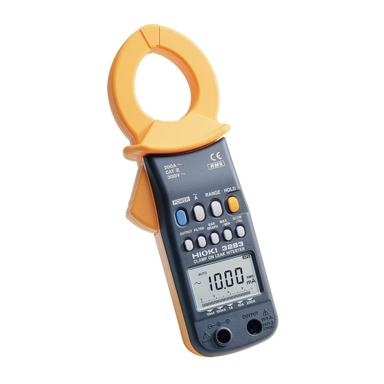
1.3 Parts and Functions Top and Side View ① ⑦ ② ③ ⑧ ④ ⑥ ⑤ Chapter 1 Product Outline... - Page 21 ① Clamp sensor ② Operation lever ③ Key switches ④ Display (LCD) ⑤ Ou tput jack ⑥ AC adapter jack ⑦ Rear cover ⑧ Hand Strap Chapter 1 Product Outline...
- Page 22 AUTO Auto-range SLOW Update display once every 3 seconds Record function Maximum value Minimum value Average value = (maximum value + minimum value/2) 1 minute/segment (bar graph) hour 1 hour/segment (bar graph) Data hold function HOLD Auto power off function Waveform output (AC) is active Recording output (DC) is active FILTER Filter function is active...
-
Page 23: Preparations
Chapter 2 Measurement Procedure 2.1 Preparations 1. Remove the r ear cover a n d insert the battery. (Refer to "Chapter3 Battery Replacement".) 2. Press the key to t u r n the unit on. POWER Verify t h a t all segments of the display light up briefly. -
Page 24: Leak Current Measurement ∼A
~ ~ ~ ~ 2.2 Leak Current Measurement A ∼ ∼ ∼ ∼ 1. Press the key. 2. Clamp the tester on the conductor, so t h a t the conductor passes through the center of the clamp core. For measurement of grounded leads, clamp the tester on one lead only (see a). - Page 25 three-phase 3-lead clamp all three leads of the circuit circuits Load device Class 2 grounding line Class 3 grounding line ・ For measurement of single-phase 2-lead NOTE circuits, clamp both leads of the circuit. ・ For measurement of three-phase 4-lead circuits, clamp all four leads of the circuit.
- Page 26 ・ Do not input a current which exceeds the NOTE maximum continuous input rating. ・ When the clamp is open a n d while the range is being changed, a n indicated value in the range of tens may appear; this is not a malfunction.
- Page 27 3. For detection of intermittent leak current conditions (such as only when a certain piece of equipment is operating), the use of a level recorder will be helpful. single-phase 3-lead b′ circuits c′ Load Load device device 【Range switching】 Each push of the key switches the RANGE range in the order 10 mA →...
- Page 28 【Bar graph display BAR GRAPH】 The current range display can be switched to bar graph operation. The bar graph shows the r m s value of the measured current. 1. Press the key. BAR GRAPH 2. The current range display is switched to bar graph operation.
- Page 29 ・ Spurious display indications may be produced NOTE as a result of noise. In this case, enable the filter function. ・ If the input is less t h a n 1/10 of the full-scale value, or if the filter function is activated for measurement of high frequencies, the frequency indication may not be accurate.
-
Page 30: Filter
2.3 Filter Function FILTER The widespread use of switching power supplies a n d equipment incorporating inverter technology can cause harmonics to be superimposed on the leak current waveform. key. The FILTER indication 1. Press the FILTER appears. The integrated low-pass filter is now active, cutting off unwanted higher-frequency components. -
Page 31: Hold
2.4 Data Hold Function HOLD This function allows freezing the display a t any desired point for easy reading. 1. Press the key. The indication HOLD HOLD appears on the display a n d the digital display value is maintained. To cancel the da t a hold function, press the key again. - Page 32 3. During measurement, the key can MAX/MIN be used to select the value t h a t should be shown. MAX: Maximum value is shown. MIN: Minimum value is shown. AVE: Average value is shown = (maximum value + minimum value/2) If none of the MAX, MIN, or AVE indicators is shown, the display shows the instantaneous value.
- Page 33 【Bar graph indication BAR GRAPH】 The bar graph display can be changed. It is also possible to display the current range, effective (rms) value of the measured current, a n d the elapsed time (hours a n d minutes). 1. Press the key.
-
Page 34: Aps 18
・ Momentary power loss a n d power surges NOTE cannot be detected. ・ When the unit is tur ned off, accumulated d a t a are lost. ・ The maximum recording duration depends on the remaining battery capacity. ・ The lowest possible frequency t h a t can be displayed is 30 Hz. - Page 35 Pressing any key except the key will POWER extend the powered state for another 10 minutes. To disable the auto power-off function, hold down the key while turning the unit HOLD on by pressing the key. The POWER indication t hen is not shown. While using the recording function or the output function of the unit, auto power-off is disabled.
- Page 36 2.9 Fast Mode The digital display update ra te can be set to 4 times per second. This is useful for example for inrush current measurements a nd similar applications. ∼ ∼ ∼ ∼ 1. Press the key twice in succession. The indication "F"...
-
Page 37: Output
2.10 Output Function OUTPUT An output signal corresponding to the measured value can be obtained from the unit. The output voltage (AC/DC) normally is 1 V for the full-scale count (1000). In the 200 A range, the output voltage (AC/DC) is 2 V for the full-scale count (2000). - Page 38 ・ To use the output function, be sure to push NOTE key so t h a t either OUTPUT is shown. ・ There is no frequency output function. ・ The filter function can be used to cut unwanted high- frequency components. ・...
- Page 39 【Output rate】 (waveform output : AC), (recording output : DC) Current Crest Output rate Accuracy Range Factor 10 mA AC/DC 1 V/10 mA 40 Hz to 25 Hz 100 mA AC/DC 1 V/100 mA 2.5or less AC/DC: 1 A AC/DC 1 V/1 A ±3.0%rdg 10 A AC/DC 1 V/10 A ±10 mV...
- Page 40 Chapter 2 Measurement Procedure...
-
Page 41: Battery Replacement
Chapter 3 Battery Replacement 1. Remove the two fastening screws of the rear cover, using a Phillips screwdriver. 2. Remove the r ear cover. 3. Remove the old battery without pulling the codes of the snap. 4. Securely connect the battery to the battery snap. - Page 42 Chapter 3 Battery Replacement...
-
Page 43: Chapter 4 Attaching The Hand Strap
Chapter 4 Attaching the Hand Strap Explains how to attach the h a n d strap, for easy handling of the unit in the field. Chapter 4 Attaching the Hand Strap... - Page 44 Chapter 4 Attaching the Hand Strap...
-
Page 45: Chapter 5 Specifications
Chapter 5 Specifications 5.1 Measurement Specifications (23℃ ℃ ℃ ℃ ± ± ± ± 5℃ ℃ ℃ ℃ , 80% RH max.) 5.1.1 AC current Arms (true rms indication) Accuracy Maximum Current Range Resolution (NOTE) permitted (Accuracy Range) ±(%rdg.+dgt.) current 10 mA 0.01 mA (1.00 to 10.00 mA) -
Page 46: Frequency Hz
Effect of conductor within ±0.1% (in any direction position from sensor center) 100 A MAX: within ±0.5% Effect of external AC 400 A/m corresponds to 5 mA, magnetic fields max. 7.5 mA Voltage in measured max. 300 Vrms AC (insulated circuit conductor) Frequency [Hz]... -
Page 47: General Specifications
5.2 General Specifications ○Functions Recording Maximum (MAX), min imum (MIN), average (AVE) value display selectable for AC current an d frequency measu rement Data hold Data hold function Auto power-off Automatic shutdown after 10.5±1 minutes. Beep tone warning. Extension an d disabling possible. Beep tone ON/OFF ○Display... -
Page 48: Output Function Output
Display update rate Digital indication NORMAL 500 ms±25 ms (approx. 2 times/second) SLOW 3 s±0.15 s (approx. 1 time/3 seconds) FAST 250 ms±12.5 ms (approx. 4 times/second) Bar graph FAST only Display response time 2.2 s max. Range switching Auto range, man u al (fixed) range (selectable). - Page 49 Insulation resistance Clamp core - circuitry: 630 kilohms min. Location for use Indoor, altitude up to 2000 m Applicable standards Safety: EN61010-1:1993+A2:1995 Voltage input: Pollution level 2, overvoltage categoryⅢ (expected tran sient overvoltage: 4000 V) EN61010-2-032:1995 EN60529:1991 IP40 (protected against access to hazardous p arts with a wire) EMC: EN55011:1991+A2:1996 Group1...
- Page 50 Mass approx. 400 g Accessories 9399 CARRYING CASE 1 Ha nd Strap 6F22(006P) Instruction manual Options 9445 AC ADAPTER (UP01211090, POTRANS) 9094 OUTPUT CORD Chapter 5 Specifications...
-
Page 51: Chapter 6 Troubleshooting
Chapter 6 Troubleshooting If the unit seems not to be working normally, check the following points first before requesting service. Symptom Battery Battery clip Unit does not come on. indication appears an d unit immediately t u r n s off. indication appears. - Page 52 Chapter 6 Troubleshooting...
-
Page 53: Chapter 7 Service
・ The minimum stocking period for replacement p art s is five years after end of production. ・ For information regarding service, please contact your dealer or the nearest HIOKI representative. ・ If the unit is not functioning properly, check the battery. - Page 54 Chapter 7 Service...
-
Page 57: Instruction Manual
HIOKI 3283 CLAMP ON LEAK HiTESTER Instruction Manual Publication date: J a n u a r y 2000 Revised edition 5 Edited an d published by HIOKI E.E. CORPORATION Technical Support Section All inquiries to Sales an d Marketing International Department... - Page 58 HEAD OFFICE 81 Koizumi, Ueda, Nagano 386-1192, Japan TEL +81-268-28-0562 / FAX +81-268-28-0568 E-mail: os-com@hioki.co.jp HIOKI USA CORPORATION 6 Corporate Drive, Cranbury, NJ 08512, USA TEL +1-609-409-9109 / FAX +1-609-409-9108 3283A980-05 00-01-001H Printed on recycled paper...
Need help?
Do you have a question about the 3283 and is the answer not in the manual?
Questions and answers