Table of Contents
Advertisement
Advertisement
Table of Contents

Related Manuals for Hioki 3237


Summary of Contents for Hioki 3237
- Page 1 3237,3237-01 3238,3238-01 Instruction Manual 3239,3239-01 DIGITAL HiTESTER 99 Washington Street Melrose, MA 02176 Phone 781-665-1400 Toll Free 1-800-517-8431 Visit us at www.TestEquipmentDepot.com Nov. 2016 Revised edition 14 3237A981-14 16-11H * 6 0 0 1 9 5 0 1 E *...
-
Page 3: Table Of Contents
Contents Introduction Inspection Safety Notes Notes on Use Chapter Summary Chapter 1 Overview 1.1 Product Overview 1.2 Major Features 1.3 Names and Functions of Parts 1.3.1 Front Panel 1.3.2 Rear Panel Chapter 2 Installation and Preparation 2.1 Power Supply and Ground Connection 2.2 Test Lead/Clamp Sensor Connection 2.3 Power On/Off 2.4 Selection of Power-supply Frequency... - Page 4 3.7 Current Measurement (3238/39) 3.7.1 DC Current Measurement 3.7.2 AC Current Measurement 3.8 Clamp Current Measurement 3.8.1 DC Clamp Current Measurement (9277/9278/9279/3284/3285) 3.8.2 AC Clamp Current Measurement Chapter 4 Basic Functions 4.1 Selection of Measurement Range 4.2 Switching of Sampling Period 4.3 Zero Adjust function 4.4 Average function 4.5 Trigger Function...
- Page 5 Chapter 9 Printer Interface 9.1 Setup for Interface 9.2 Setup for Printer 9.3 Printer Connection Method 9.4 Sample Prints Chapter 10 Specifications 10.1 General Specifications 10.2 Accuracy 10.2.1 Accuracy of the 3237 10.2.2 Accuracy of the 3238 10.2.3 Accuracy of the 3239...
- Page 6 Chapter 11 Maintenance and Service 11.1 A-Terminal Fuse Replacement (3238/39) 11.2 Power Supply Fuse Replacement 11.3 Cleaning 11.4 Service Appendix APPENDIX1...
- Page 7 Before using the product, make sure that the insulation on the probes is undamaged NOTE and that no bare conductors are improperly exposed. Using the product in such conditions could cause an electric shock, so contact your dealer or Hioki representative for repair. ______________________________________________________________________________________________...
-
Page 8: Safety Notes
_____________________________________________________________________________________________ Safety Notes This instrument is designed to comply with IEC 61010 Safety Standards, and has been thoroughly tested for safety prior to shipment. However, WARNING mishandling during use could result in injury or death, as well as damage to the instrument. Be certain that you understand the instructions and precautions in the manual before use. - Page 9 _____________________________________________________________________________________________ Measurement categories This product complies with CAT II safety requirements. To ensure safe operation of measurement product, IEC 61010 establishes safety standards for various electrical environments, categorized as CAT II to CAT IV, and called measurement categories. CAT II Primary electrical circuits in equipment connected to a wall outlet via a power cord (portable tools, household appliances, etc.)
- Page 10 _____________________________________________________________________________________________ Accuracy The specifications in this manual include figures for "measurement accuracy" when referring to digital measuring instruments, and for "measurement tolerance" when referring to analog instruments. f.s. (maximum display or scale value, or length of scale) Signifies the maximum display (scale) value or the length of the scale (in cases where the scale consists of unequal increments or where the maximum value cannot be defined).
-
Page 11: Notes On Use
_____________________________________________________________________________________________ Notes on Use In order to ensure safe operation and to obtain maximum performance from the unit, observe the cautions listed below. To avoid electric shock, do not allow the product to get wet, and do not use it when your hands are wet. WARNING Do not use the product where it may be exposed to corrosive or combustible gases. -
Page 12: Chapter Summary
_____________________________________________________________________________________________ Chapter Summary Chapter 1 Overviews Provides a product overview and gives the names and describes the functions of the component parts. Chapter 2 Installation and Preparation Describes ways to turn on power, connect test leads, and set up the power- supply frequency. -
Page 13: Chapter 1 Overview
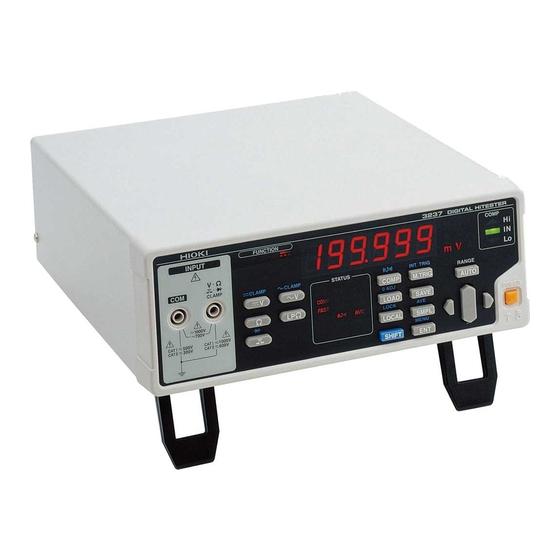
1.1 Product Overview In addition to measuring functions for DC voltages, AC voltages, resistances, DC currents*, AC currents*, and frequencies*, the 3237/38/39 Digital High Tester comes with a comparator function that is especially useful for line use. The GP-IB interface (3237-01/3238-01/3239-01), RS-232C interface, and the units comparator output permits use of the unit across a wide range of applications, such as parts selection and data acquisition. -
Page 14: Names And Functions Of Parts
_____________________________________________________________________________________________ 1.3 Names and Functions of Parts 1.3.1 Front Panel V Ω 3237 CLAMP terminal Display terminal Power switch Operation keys V Ω 3238 CLAMP terminal Display terminal Power swtich A-terminal Operation keys SENSE terminal V Ω 3239 CLAMP terminal... - Page 15 _____________________________________________________________________________________________ Operation keys Selects the DC voltage measurement function. Selects the AC voltage measurement function. Selects the 2-terminal resistance measurement function. Ω Selects the low-power 2-terminal resistance measurement LPΩ function. Selects the continuity test function. Selects the diode test function. SHIFT Selects the frequency measurement function.
- Page 16 _____________________________________________________________________________________________ Operation keys Selects the 4-terminal resistance measurement function. 4WΩ (3239 only) Ω SHIFT Selects the low-power 4-terminal resistance measurement 4WΩ function. (3239 only) LPΩ SHIFT Displays the menu screen for selection of the clamp sensor, MENU interfaces, power-supply frequency, etc. SHIFT Terminals The test lead (black) is connected here for various...
- Page 17 _____________________________________________________________________________________________ COMP FUNCTION STATUS LED display Lights up when a low-power resistance measurement is performed. Lights up when a DC measurement is performed. CLAMP Lights up when a current measurement is performed using the clamp sensor. Lights up when a AC measurement is performed. Lights up when a diode test is conducted.
-
Page 18: Rear Panel
_____________________________________________________________________________________________ 1.3.2 Rear Panel Power/fuse ratings 3237 3238 Inlet 3239 Stand RS-232C interface External I/O Power/fuse ratings 3237-01 3238-01 Inlet 3239-01 GP-IB interface Stande RS-232C interface External I/O Inlet The power cord is connected here. GP-IB interface The GP-IB interface is connected here. -
Page 19: Chapter 2 Installation And Preparation
_____________________________________________________________________________________________ Chapter 2 Installation and Preparation 2.1 Power Supply and Ground Connection Before turning the product on, make sure the source voltage matches that indicated on the product's power connector. Connection to an WARNING improper supply voltage may damage the product and present an electrical hazard. -
Page 20: Test Lead/Clamp Sensor Connection
_____________________________________________________________________________________________ 2.2 Test Lead/Clamp Sensor Connection The terminals do not have sufficient spatial isolation. To avoid electrocution, observe the following precautions. WARNING Connect test leads to the terminals only after shutting off the line power. Note that hazardous voltage may be present at the V Ω CLAMP terminal when using the A-terminal. - Page 21 _____________________________________________________________________________________________ (1) Voltage measurement/ 2-terminal resistance measurement/ continuity test/ diode test/ frequency measurement 3237/38 3239 . Disconnect the L9170-10 TEST LEAD from the sample being measured. . Connect the black lead to the COM terminal and the red lead to the V Ω...
-
Page 22: Power On/Off
_____________________________________________________________________________________________ 2.3 Power On/Off (1) How to turn on power Turn on ( ) the power switch on the front panel. All the LEDs on the front panel will light to indicate the model, software version and power-supply frequency of the unit. The unit readies itself for measurement. -
Page 23: Chapter 3 Measurement Procedure
_____________________________________________________________________________________________ Chapter 3 Measurement Procedure Observe the following precautions to avoid electric shock. Always verify the appropriate setting of the measuring function before DANGER connecting the test leads. Disconnect the test leads from the measurement object before changing the measuring function. Clamp sensor/ Clamp-on probe/ Test leads should only be connected to the secondary side of a breaker, so the breaker can prevent an accident if a short circuit occurs. -
Page 24: Voltage Measurement
Hz). Attempting to measure voltage in excess of the maximum rating DANGER could destroy the product and result in personal injury or death. 3237/38 3239 Check to make sure that the black lead of the L9170-10 TEST LEAD is connected to the COM terminal and the red lead to the V Ω... -
Page 25: 2-Terminal Resistance Measurement
. Press to select a sampling period. SMPL (See 4.2 Switching of Sampling Period.) . Performs zero-ajust for the 3237/38/39. (See 4.3 Zero Ajust Function.) . Connect the test lead to the sample being measured and read the value. ______________________________________________________________________________________________... -
Page 26: Low-Power Resistance Measurement (2-Terminal)
. Press to select a sampling period. SMPL (See 4.2 Switching of Sampling Period.) . Performs zero-ajust for the 3237/38/39. (See 4.3 Zero Ajust Function.) . Connect the test lead to the sample being measured and read the value. ______________________________________________________________________________________________... -
Page 27: 4-Terminal Resistance Measurement
SMPL (See 4.2 Switching of Sampling Period.) . Performs zero-ajust for the 3237/38/39. (See 4.3 Zero Ajust Function.) . Connect the test lead to the sample being measured and read the value. When clipping a thin line... -
Page 28: Low-Power Resistance Measurement (4-Terminal, On 3239 Only)
SMPL (See 4.2 Switching of Sampling Period.) . Performs zero-ajust for the 3237/38/39. (See 4.3 Zero Ajust Function.) . Connect the test lead to the sample being measured and read the value. When measurement is performed using the low-power resistance measurement... -
Page 29: Diode Test
DANGER To avoid electrical accidents, remove power from the circuit before measuring. 3237/38 3239 Check to make sure that the black lead of the L9170-10 TEST LEAD is connected to the COM terminal and the red lead to the V Ω... -
Page 30: Frequency Measurement (3238/39)
_____________________________________________________________________________________________ 3.6 Frequency Measurement (3238/39) The maximum rated working voltage is 600 VDC/700 VrmsAC (10 V Hz). Attempting to measure voltage in excess of the maximum rating could DANGER destroy the product and result in personal injury or death. 3238 3239 Check to make sure that the black lead of the L9170-10 TEST LEAD is connected... -
Page 31: Current Measurement (3238/39)
_____________________________________________________________________________________________ 3.7 Current Measurement (3238/39) The maximum rated working current is 2 ADC/AC. Attempting to input current in excess of the maximum rating could destroy the product DANGER and result in personal injury or death. Never apply voltage to A-terminal. Doing so may damage the product and result in personal injury. -
Page 32: Clamp Current Measurement
Before using the clamp sensor, carefully read the supplied instruction manual. NOTE The Auto Range function cannot be used in clamp current measurement. 3237, 3238 3239 Black Connect the Clamp sensor connector to the 9704 CONVERSION ADAPTER. -
Page 33: Dc Clamp Current Measurement (9277/9278/9279/3284/3285)
_____________________________________________________________________________________________ 3.8.1 DC Clamp Current Measurement (9277/9278/9279/3284/3285) . Press . " " lights up on the display. SHIFT SHIFT . Press . Press to select a clamp sensor range. . Press to select a sampling period. SMPL (See 4.2 Switching of Sampling Period.) . -
Page 34: Ac Clamp Current Measurement
_____________________________________________________________________________________________ 3.8.2 AC Clamp Current Measurement . Press . " " lights up on the display. SHIFT SHIFT . Press . Press to select a clamp sensor range. (Clamp sensor: 9010-50/9018-50/9132-50/3283/3284/3285) (See 4.1 Selection of Measurement Range.) . Press to select a sampling period. SMPL (See 4.2 Switching of Sampling Period.) . -
Page 35: Chapter 4 Basic Functions
When FAST is chosen for the sampling period, the unit performs a self- NOTE calibration every 30 minutes. Each self-calibration takes approximately 55 ms. In a continuity test, only FAST can be selected for the sampling period. *: Self-calibration: 3237/38/39 automatically self-correct offset and gain. ______________________________________________________________________________________________ 4.2 Switching of Sampling Period... -
Page 36: Zero Adjust Function
_____________________________________________________________________________________________ 4.3 Zero Adjust function The Zero-Adjust function displays the computed result after subtracting the Zero-Adjusted value (reference value) from the measurement data. The function can be used to cancel an offset, such as the resistance of the test lead, or to check the deviation from the reference value. . -
Page 37: Average Function
_____________________________________________________________________________________________ 4.4 Average function The Average function outputs a mean value after averaging measurement values. This function allows you to minimize the deviation of measurement values. The averaging can be set to 2 to 100 measurements. . Press . " "... -
Page 38: Trigger Function
_____________________________________________________________________________________________ 4.5 Trigger Function 4.5.1 Setup for Trigger mode The following two types of Trigger modes are available: (1) Internal Trigger Continuous measurement is performed with an automatically generated internal trigger. . Press . " " lights up on the display. SHIFT SHIFT . -
Page 39: Trigger Delay
_____________________________________________________________________________________________ 4.5.3 Trigger Delay The delay time from the application of a trigger signal until the start of measurement is set. If this function is in use, measurement begins when the measurement values have stabilized, even if a trigger is applied immediately following the connection of the sample. - Page 40 _____________________________________________________________________________________________ (2) Manual Delay Any desired delay time can be set. The trigger delay time can be set from 0.000 to 9.999 s in increments of 1 . Press . " " lights up on the display. SHIFT SHIFT . Pressing displays the menu screen.
-
Page 41: Trigger System
_____________________________________________________________________________________________ 4.5.4 Trigger System The trigger system functions as described further below, depending on the setting for the Continuous trigger state ( ) or for the :INITIATE:CONTINUOUS Trigger Source ( ). For trigger commands, refer to 7.4.3 :TRIGGER:SOURCE "Specific Command Messages." Continuous trigger state :INITIATE:CONTINUOUS OFF*... - Page 42 _____________________________________________________________________________________________ :INITIATE:CONTINUOUS ON :INITIATE:CONTINUOUS ON :TRIGGER:SOURCE EXTERNAL :TRIGGER:SOURCE IMMEDIATE Wait state for trigger Measurement TRIG terminal M.TRIG Computed result Trigger delay Measurement Measurement value output computed result Measurement value output :INITIATE:CONTINUOUS OFF :INITIATE:CONTINUOUS OFF :TRIGGER:SOURCE EXTERNAL :TRIGGER:SOURCE IMMEDIATE Idle state Idle state :INITIATE:IMMEDIATE :INITIATE:IMMEDIATE...
-
Page 43: Chapter 5 Other Functions
_____________________________________________________________________________________________ Chapter 5 Other Functions 5.1 Comparator Function The Comparator function compares the measurement value with the upper- limit and lower-limit values previously set, determines the appropriate range for the measurement value, and displays the determination. The flow of comparator setup is given below: Setting of comparator Measurement (comparator: OFF) COMP... - Page 44 _____________________________________________________________________________________________ Described below is the flow of operations from the measurement state with comparator OFF to the start of the measurement state using the comparator. In the following example, the upper-limit value will be set to 12 V and the lower-limit value to 8 V.
- Page 45 _____________________________________________________________________________________________ To turn the comparator OFF If you press while the unit is measuring with the comparator ON, the COMP unit shifts to measurement with the comparator OFF. Pressing on the upper-limit value setup screen or lower-limit value setup COMP NOTE screen opens the following screen without altering the current upper-limit or lower-limit value.
-
Page 46: Comparator Buzzer Sound
_____________________________________________________________________________________________ 5.2 Comparator Buzzer Sound Set the buzzer to sound at comparator determination. Press lights up on the display. " " SHIFT SHIFT Press . The comparator buzzer sound setup screen opens, and the COMP current setting for the comparator buzzer flashes. . -
Page 47: Panel Save Function
_____________________________________________________________________________________________ 5.3 Panel Save Function The current measurement conditions are saved to the built-in nonvolatile memory. A maximum of 30 different measurement conditions may be saved. All the conditions in effect when Panel Save is executed are saved. The saved measurement conditions can be loaded with the Panel Load function described further below. -
Page 48: Panel Load Function
_____________________________________________________________________________________________ 5.4 Panel Load Function This function loads the measurement conditions saved by Panel Save from the built-in nonvolatile memory. Press . The Panel Load setup screen opens, and the numerical LOAD value indicating the panel number flashes. . Press to select the panel number from which you want to load data. -
Page 49: Key Operation Sound
_____________________________________________________________________________________________ 5.5 Key Operation Sound The setting made here determines whether or not the key operation sound should be emitted when a key is pressed on the front panel of the main unit. Press lights up on the display. " "... -
Page 50: Key Lock Function
_____________________________________________________________________________________________ 5.6 Key Lock Function When Key Lock is executed, the key switches on the front panel are disabled. The set data can be protected with the Key Lock function. . Set measurement conditions. Press lights up on the display. "... -
Page 51: Remote Function
_____________________________________________________________________________________________ 5.7 Remote Function This unit can be controlled externally through the RS-232C or GP-IB interface. When the unit is placed in remote status (remote operation state), " " on the display lights up, and the keys on the front panel are disabled. Clearing the Remote function Pressing clears the Remote function. -
Page 52: System Reset
_____________________________________________________________________________________________ 5.8 System Reset System Reset is a function designed to initialize all measurement conditions to their initial factory settings. Performing a System Reset also initializes data stored via Panel Save. Press lights up on the display. " " SHIFT SHIFT Pressing displays the menu screen. - Page 53 _____________________________________________________________________________________________ The unit factory settings are as follows: Measurement function Low-power 2-terminal resistance measurement: zero ajust function DC voltage measurement: range Auto range 4-terminal resistance measurement: zero ajust function AC voltage measurement: range Auto range Low-power 4-terminal resistance measurement: zero ajust function 2-terminal resistance measurement: Auto range DC current measurement: zero ajust...
-
Page 54: Measurement States And Effective Keys
_____________________________________________________________________________________________ 5.9 Measurement States and Effective Keys Condition FUNCTION AUTO COMP Normal - LOCK - - - - - - - - - - - - COMP - - - - Condition M.TRIG INT.TRIG LOAD SAVE 0ADJ LOCAL Normal - LOCK -... -
Page 55: Chapter 6 External Control Terminal
_____________________________________________________________________________________________ Chapter 6 External Control Terminal / External output terminal (1) External control terminal functions External trigger input Selection of panel number to be loaded (2) External output terminal function Measurement end signal output Output of comparator determination signal (3) Connectors in use 57RE-40360-730B(D29) (DDK Ltd) (4) Acceptable connector JC57-30360 (JC Electronics Corporation) -
Page 56: Explanation Of Signal Wires
_____________________________________________________________________________________________ 6.1 Explanation of Signal Wires To prevent damage to this unit, please observe the following precautions: CAUTION Do not apply a voltage or current exceeding the rated values to the external output terminal or external control terminal. When using a relay, always attach a flyback diode. Take care not to short-circuit the external output terminal and the external control terminal. - Page 57 _____________________________________________________________________________________________ (1) LOAD0~LOAD4 These signals select the panel number from which to load data. When a trigger signal is applied in External Trigger mode, the unit loads data from the selected panel number and performs a measurement. LOAD0 is the LSB, and LOAD4 is the MSB. (The number 0 indicates that the LOAD terminal should be shorted by the INT.GND, and the number 1 indicates that the LOAD terminal should be open.) LOAD4...
-
Page 58: Timing Chart
_____________________________________________________________________________________________ (4) EOC This is a measurement end signal. (5) Hi, IN, Lo These are comparator determinations. In the following cases, input signals will be ineffective. NOTE Trigger in the Internal Trigger mode (TRIG) Trigger in any screen other t h a n meas urement screens (TRIG). Panel Load in remote status. - Page 59 _____________________________________________________________________________________________ Time Contents Measurement trigger ( TRIG ) - - pulse width Trigger delay time Refer to 4.5.3 Trigger Delay Measuring time* FAST 3.3 ms - - MEDIUM 130 ms (50 Hz) / 108 ms (60 Hz) SLOW 1.04 s (50 Hz) / 1.08 s (60 Hz) Computing time 2 ms -...
-
Page 60: Internal Circuit Configuration
_____________________________________________________________________________________________ 6.3 Internal Circuit Configuration (1) Power rating for external control and output terminals Input/output device Logic Electrical requirements Output Open collector Negative logic DC35 V, DC50 mAmax. Input C-MOS Negative logic H: 3.8 to 5.0 V, L: 0 to 1.2 V INT.DCV Internal power supply 1 0%, ±... -
Page 61: Chapter 7 Rs-232C Interface
RS-232C and GP-IB (-01) cannot be used simultaneously. Select either of them. For information on performing the selection, refer to 7.1 Preparations for Communication. (1) Specifications 3237/38/39 RS-232C settings are configured as follows and cannot be modified. Modify and adjust personal computer settings. Transmission mode Start-stop synchronization, full duplex... - Page 62 +5 V to +9 V: ON, -9 V to -5 V: OFF (Load resistance 3 to 7 kΩ) 3237/38/39 RS-232C connector signal lead is set as follows. Other pins are not in use. Interface connector: D-sub 9 pin, male Signal...
-
Page 63: Preparing For Data Transfer
(2) Connecting 3237/38/39 and Personal Computer . Use cable to connect 3237/38/39 and personal computer. . After connecting, turn on both 3237/38/39 and personal computer power. . Set RS-232C in personal computer. Set hardware flow OFF in personal computer flow control setting. - Page 64 _____________________________________________________________________________________________ (3) 3237/38/39 Interface Setting Designate 3237/38/39 Interface setting " "(RS-232C) to enable 3237/38/39 Interface to communicate with personal computer. Press lights up on the display. " " SHIFT SHIFT Pressing displays the menu screen. Press to display the interface setup screen.
-
Page 65: Communication
:INIT immediately followed by the delimiter. The meaning of the delimiter is to separate commands and data. When the NOTE 3237/38/39 receives the delimiter, it starts analysis of the command. ______________________________________________________________________________________________ 7.2 Communication... - Page 66 Examples: ∗RST etc. ② Parameter Character data and decimal data are used as the 3237/38/39 parameter (data) and the command determines the type of data. The 3237/38/39 uses character string data and numeric data, and the type use varies according to the command in question.
- Page 67 _____________________________________________________________________________________________ ③ Delimiter Depending on transmission direction, the delimiter is as follows. From computer to 3237/38/39: CR or CR + LF From 3237/38/39 to computer: CR + LF (3) Separators ① Command unit separator Multiple commands can be written in a line by connecting them with a semicolon";".
- Page 68 The output queue is also cleared when the power is turned off and turned on again. The 3237/38/39 has an output queue of 64 bytes capacity. If the response messages overflow this limit of 64 bytes, a query error is generated, and the output queue is cleared.
- Page 69 The status byte register is an 8-bit register whose contents are output from the 3237/38/39 to the controller, when serial polling is being performed. If even only one bit in the status byte register has changed from 0 to 1 (provided that it is a bit which has been set in the service request enable register as a bit which can be used), then the MSS bit is set to 1.
-
Page 70: Standard Event Registers
_____________________________________________________________________________________________ Standard Event Registers (1) Standard event status register (SESR) The standard event status register is an 8-bit register. If any bit in the standard event status register is set to 1 (after masking by the standard event status enable register), bit 5 (ESB) of the status byte register is set to 1. Standard event status registers (SESR) bit6 bit5... - Page 71 Bit 7 Power-on flag PON is set to "1" when the 3237/38/39 is turned on or restored from a power failure and switching the interface. Bit 6 User request This bit is not used in the 3237/38/39.
- Page 72 8-bit event status registers are provided for managing events on the 3237/38/39. If any bit in one of these event status registers is set to 1 (after masking by the corresponding event status enable register), bit 0 of the status byte register (ESB0) is set to 1.
- Page 73 _____________________________________________________________________________________________ (2) Event status enable register 0 These event status enable registers mask the corresponding event status registers. Bit 7 Not used Bit 6 Not used Bit 5 Minus over load Bit 4 Plus over load Bit 3 Comparator result: Hi Bit 2 Comparator result: IN Bit 1...
-
Page 74: Command Code Table
_____________________________________________________________________________________________ 7.3 Command Code Table 7.3.1 Common Command Input/output Message Meaning data format Clears the status byte register and the event ∗CLS registers. NR1 numerical data (1) Sets the standard event status enable register. ∗ESE NR1 numerical data (1) Read the standard event status enable register ∗ESE? (SESER). -
Page 75: Specific Command
_____________________________________________________________________________________________ 7.3.2 Specific Command Set and inquiry concerning event status register Command Input/output data format Initial value :ESE0 NR1 numerical data (1) :ESE0? NR1 numerical data (1) :ESR? NR1 numerical data (1) Select and inquiry concerning measurement function Command Input/output data format Initial value [:SENSe:]FUNCtion 'VOLTage[:DC]'/'VOLTage:AC'/... - Page 76 _____________________________________________________________________________________________ Set and inquiry concerning Auto Range Command Input/output data format Initial value [:SENSe:]VOLTage[:DC]:RANGe:AUTO ON/OFF or 1/0 [:SENSe:]VOLTage[:DC]:RANGe:AUTO? ON/OFF [:SENSe:]VOLTage:AC:RANGe:AUTO ON/OFF or 1/0 [:SENSe:]VOLTage:AC:RANGe:AUTO? ON/OFF [:SENSe:]CURRent:DC:RANGe:AUTO ON/OFF or 1/0 [:SENSe:]CURRent:DC:RANGe:AUTO? ON/OFF [:SENSe:]CURRent:AC:RANGe:AUTO ON/OFF or 1/0 [:SENSe:]CURRent:AC:RANGe:AUTO? ON/OFF [:SENSe:]RESistance:RANGe:AUTO ON/OFF or 1/0 [:SENSe:]RESistance:RANGe:AUTO? ON/OFF [:SENSe:]LPResistance:RANGe:AUTO...
- Page 77 _____________________________________________________________________________________________ Set and inquiry concerning Zero-Adjust execution Command Input/output data format Initial value [:SENSe:]VOLTage[:DC]:REFerence:STATe ON/OFF or 1/0 [:SENSe:]VOLTage[:DC]:REFerence:STATe? ON/OFF [:SENSe:]VOLTage:AC:REFerence:STATe ON/OFF or 1/0 [:SENSe:]VOLTage:AC:REFerence:STATe? ON/OFF [:SENSe:]CURRent:DC:REFerence:STATe ON/OFF or 1/0 [:SENSe:]CURRent:DC:REFerence:STATe? ON/OFF [:SENSe:]CURRent:AC:REFerence:STATe ON/OFF or 1/0 [:SENSe:]CURRent:AC:REFerence:STATe? ON/OFF [:SENSe:]RESistance:REFerence:STATe ON/OFF or 1/0 [:SENSe:]RESistance:REFerence:STATe? ON/OFF [:SENSe:]LPResistance:REFerence:STATe...
- Page 78 _____________________________________________________________________________________________ Set and inquiry concerning comparator lower-limit value Command Input/output data format Initial value :CALCulate:LIMit:LOWer NRf numerical data :CALCulate:LIMit:LOWer? NR1 numerical data Set and inquiry concerning comparator execution Command Input/output data format Initial value :CALCulate:LIMit:STATe ON/OFF or 1/0 :CALCulate:LIMit:STATe? ON/OFF Inquiry concerning comparator determination Command Input/output data format...
- Page 79 _____________________________________________________________________________________________ Set and inquiry concerning delimiter Command Input/output data format Initial value :SYSTem:TERMinator NR1 numerical data :SYSTem:TERMinator? 0/1 (0: LF, 1: CR+LF) Set and inquiry concerning Continuous Trigger state Command Input/output data format Initial value :INITiate:CONTinuous ON/OFF or 1/0 :INITiate:CONTinuous? ON/OFF Setup of Trigger Wait state Command...
- Page 80 _____________________________________________________________________________________________ Presetting of Ranges and Functions Command Input/output data format Initial value :CONFigure:VOLTage[:DC]? NRf numerical data :CONFigure:VOLTage:AC? NRf numerical data :CONFigure:CURRent:DC? NRf numerical data :CONFigure:CURRent:AC? NRf numerical data :CONFigure:RESistance? NRf numerical data :CONFigure:LPResistance? NRf numerical data :CONFigure:FRESistance? NRf numerical data :CONFigure:LPFResistance? NRf numerical data :CONFigure:CLAMp:DC?
-
Page 81: Command Reference
_____________________________________________________________________________________________ 7.4 Command Reference 7.4.1 Explanation of Command Reference Command Indicates functions of command reference Syntax Indicates the command syntax. data Indicates the data format for a command that includes data. Function Describes points that require special attention when using the command. Note Indicates the what kinds of errors might occur. -
Page 82: Common Command Messages
_____________________________________________________________________________________________ 7.4.2 Common Command Messages ∗CLS command Clears the status byte register and the event registers. Syntax ∗CLS Function This instruction clears the event registers and the bits of the status byte register associated with that register (SESR, STB). Note This has no effect upon the output queue, the various enable registers, or bit 4 (the MAV bit) of the status byte register. - Page 83 Third field Not used - always "0" Fourth field Software version Example Headers: ON Transmission ∗IDN? Response ∗IDN HIOKI,3237,0,V2.00 Headers: OFF Transmission ∗IDN? Response HIOKI,3237,0,V2.00 ∗OPC command Sets the standard event status register bit0 (OPC bit) to "1." Syntax ∗OPC Function This command sets the standard event status register (SESR) bit0 (OPC bit) to "1"...
- Page 84 This command sets the available patterns of the service request enable resister (SRER) to the status byte register (STB). Note When 3237/38/39 is turned on or I/F is switched, the data is reset to "0." Bit 6 is set to 0. Example Transmission ∗SRE 32...
- Page 85 The value in the MSS bit represents bit6. The MSS bit remains uncleared, even if the service request is cleared by the serial poll. Example Transmission ∗STB? Response ∗TRG command Request for sampling Syntax ∗TRG Function This command executes one sampling cycle while the 3237/38/39 is in Trigger Wait state. ______________________________________________________________________________________________ 7.4 Command Reference...
- Page 86 ∗TST? Function Causes the 3237/38/39 to perform the self test, and returns the result there of as a numerical data value in NR1 format (0 to 7). The results are shown below. When each bit is set to "1," an associated error has occurred.
-
Page 87: Specific Command Messages
_____________________________________________________________________________________________ 7.4.3 Specific Command Messages Event Status Register 0 Sets the event status enable register 0. Syntax :ESE data data NR1 numerical data numerical data 0 to 255 Function This command sets the available patterns of the standard event status register (SESR) to the event status enable register 0 (ESER0). - Page 88 _____________________________________________________________________________________________ Measurement Composition Command Selection of measurement functions Syntax [:SENSe:]FUNCtion data data Character data 'VOLTage[:DC]' DC voltage measurement 'VOLTage:AC' AC voltage measurement 'CURRent:DC' DC current measurement 'CURRent:AC' AC current measurement 'RESistance' 2-terminal resistance measurement 'LPResistance' Low-power 2-terminal resistance measurement 'FRESistance' 4-terminal resistance measurement 'LPRFesistance' Low-power 4-terminal resistance measurement 'CLAMp:DC'...
- Page 89 _____________________________________________________________________________________________ Range setup Syntax [:SENSe:]VOLTage[:DC]:RANGe data [:SENSe:]VOLTage:AC:RANGe data [:SENSe:]CURRent:DC:RANGe data [:SENSe:]CURRent:AC:RANGe data [:SENSe:]RESistance:RANGe data [:SENSe:]LPResistance:RANGe data [:SENSe:]FRESistance:RANGe data [:SENSe:]LPFResistance:RANGe data [:SENSe:]CLAMp:DC:RANGe data [:SENSe:]CLAMp:AC:RANGe data [:SENSe:]FREQuency:VOLTage:RANGe data data NRf numerical data Input the expected measurement value. The unit automatically selects the optimum range for measuring the given entered value.
- Page 90 _____________________________________________________________________________________________ Setup for Auto Range Syntax [:SENSe:]VOLTage[:DC]:RANGe:AUTO [:SENSe:]VOLTage:AC:RANGe:AUTO [:SENSe:]CURRent:DC:RANGe:AUTO [:SENSe:]CURRent:AC:RANGe:AUTO [:SENSe:]RESistance:RANGe:AUTO [:SENSe:]LPResistance:RANGe:AUTO [:SENSe:]FRESistance:RANGe:AUTO [:SENSe:]LPFResistance:RANGe:AUTO data ON/1: Auto Range enabled. OFF/0: Auto Range disabled. Function Selects to enable or disable Auto Range of th specified measurement function. Example Transmission :SENSE:VOLT:AC:RANG:AUTO ON VOLT:AC:RANG:AUTO 0 Inquiry concerning Auto Range Syntax...
- Page 91 _____________________________________________________________________________________________ Setup for clamp sensor Syntax [:SENSe:]CLAMp:MODel data data NRf numerical data 9010,9132,9018,3283,9270,9271,9272,9277,9278,9279,3284,3285 Function Selects the clamp sensor to be used in clamp current measurement. Example Transmission CLAM:MOD 9132 Inquiry concerning clamp sensor Syntax [:SENSe:]CLAMp:MODel? data NR1 numerical data Function Inquires about the model of the clamp sensor currently set.
- Page 92 _____________________________________________________________________________________________ Inquiry concerning the Zero-Adjusted value. Syntax [:SENSe:]VOLTage[:DC]:REFerence? [:SENSe:]VOLTage:AC:REFerence? [:SENSe:]CURRent:DC:REFerence? [:SENSe:]CURRent:AC:REFerence? [:SENSe:]RESistance:REFerence? [:SENSe:]LPResistance:REFerence? [:SENSe:]FRESistance:REFerence? [:SENSe:]LPFResistance:REFerence? [:SENSe:]CLAMp:DC:REFerence? [:SENSe:]CLAMp:AC:REFerence? [:SENSe:]FREQuency:REFerence? data NR3 numerical data Function Inquires about the Zero-Adjusted value. Response Headers: ON :SENSE:VOLTAGE:AC:REFERENCE data syntax Headers: OFF data Example Headers: ON Transmission CURR:DC:REF? Response...
- Page 93 _____________________________________________________________________________________________ Inquiry concerning Zero-Adjust execution Syntax [:SENSe:]VOLTage[:DC]:REFerence:STATe? [:SENSe:]VOLTage:AC:REFerence:STATe? [:SENSe:]CURRent:DC:REFerence:STATe? [:SENSe:]CURRent:AC:REFerence:STATe? [:SENSe:]RESistance:REFerence:STATe? [:SENSe:]LPResistance:REFerence:STATe? [:SENSe:]FRESistance:REFerence:STATe? [:SENSe:]LPFResistance:REFerence:STATe? [:SENSe:]CLAMp:DC:REFerence:STATe? [:SENSe:]CLAMp:AC:REFerence:STATe? [:SENSe:]FREQuency:REFerence:STATe? data Character data ON/OFF Function Inquires whether the Zero-Adjust function of the specified measurement function is enabled or disabled. Response Headers: ON :SENSE:LPRESISTANCE:REFERENCE:STATE data syntax Headers: OFF data...
- Page 94 _____________________________________________________________________________________________ Sampling Commands Setup for sampling period Syntax :SAMPle:RATE data data Chatacter data FAST,MEDium,SLOW Function Switches the sampling period. Example Transmission SAMPle:RATE MED Sets the sampling period to MEDIUM. Inquiry concerning sampling period Syntax :SAMPle:RATE? data Character data FAST,MEDIUM,SLOW Function Inquires about the sampling period currently set.
- Page 95 _____________________________________________________________________________________________ Computing Function Commands Setup for the number of averaged measurements Syntax :CALCulate:AVERage data data NRf numerical data 2 to 100 Function Sets a number of averaged measurements. Example Transmission :CALC:AVER 10 Sets the number of averaged measurements to 10. Inquiry concerning the number of averaged measurements Syntax :CALCulate:AVERage?
- Page 96 _____________________________________________________________________________________________ Setup for comparator buzzer sound Syntax :CALCulate:LIMit:BEEPer data data Character data OFF,IN,FAIL,HL Function Sets the buzzer sound to beep according to the comparator determination. Note HL is the same as FAIL. Example Transmission :CALC:LIM:BEEP IN Activates the buzzer when the comparator determination is IN. Inquiry concerning comparator buzzer sound Syntax :CALCulate:LIMit:BEEPer?
- Page 97 _____________________________________________________________________________________________ Inquiry concerning the comparator upper-limit value Syntax :CALCulate:LIMit:UPPer? data NR1 numerical data -199999 to 199999 Function Inquires about the upper-limit value of the comparator. Response Headers: ON :CALCULATE:LIMIT:UPPER data syntax Headers: OFF data Example Headers: ON Transmission :CALC:LIM:UPP? Response :CALCULATE:LIMIT:UPPER 130000 Headers: OFF Transmission...
- Page 98 _____________________________________________________________________________________________ Setup for comparator execution Syntax :CALCulate:LIMit:STATe data data ON/1: Comparator function enabled OFF/0: Comparator function disabled Function Selects whether the comparator function is to be executed or not. Note An execution error will be issued, if the comparator upper-limit value is smaller than the lower-limit value.
- Page 99 _____________________________________________________________________________________________ System-related Commands Setup for key operation sound Syntax :SYSTem:BEEPer:STATe data data ON/1: Key operation sound enabled OFF/0: Key operation sound disabled Function Sets the key operation sound. Example Transmission :SYST:BEEP:STAT 1 Key operation sound enabled. Inquiry concerning key operation sound Syntax :SYSTem:BEEPer:STATe? data...
- Page 100 _____________________________________________________________________________________________ Inquiry concerning power-supply frequency Syntax :SYSTem:LFRequency? data NR1 numerical data 50,60 Function Inquires about the setting for the power-supply frequency. Response Headers: ON :SYSTEM:LFREQUENCY data syntax Headers: OFF data Example Headers: ON Transmission :SYST:LFR? Response :SYSTEM:LFREQUENCY 60 Headers: OFF Transmission :SYST:LFR? Response...
- Page 101 _____________________________________________________________________________________________ Panel Save Syntax :SYSTem:SAVe data data NRf numerical data 1 to 30 Function Saves the current measurement conditions to the built-in nonvolatile memory. Example Transmission :SYST:SAV 3 Saves the measurement conditions under Panel No. 3. Panel Load Syntax :SYSTem:LOAD data data NRf numerical data 1 to 30...
- Page 102 _____________________________________________________________________________________________ Setup for header On/Off Syntax :SYSTem:HEADer data data ON/1: Header on OFF/0: Header off Function Sets the presence/absence (on/off) of a header in a response message. Example Transmission :SYST:HEAD 0 No header is appended to the response message. Inquiry concerning header On/Off Syntax :SYSTem:HEADer? data...
-
Page 103: Trigger Commands
_____________________________________________________________________________________________ Trigger Commands Setup of Continuous Trigger state Syntax :INITiate:CONTinuous data data ON/1: Enable Continuous Trigger state OFF/0: Disable Continuous Trigger state (One-shot trigger mode) Function Selects whether the trigger system should be placed in Continuous Trigger or One-shot trigger mode. - Page 104 _____________________________________________________________________________________________ Setup of Trigger Wait state Syntax :INITiate[:IMMediate] Function Changes the Idle state to the Trigger Wait state. Note If the unit is in the Continuous Trigger state: (:INITIATE:CONTINUOUS 1), an execution error is issued. If the trigger source is IMMediate, a trigger takes place immediately, putting the unit in the Idle state.
- Page 105 _____________________________________________________________________________________________ Inquiry concerning trigger source Syntax :TRIGger:SOURce? data Character data IMMEDIATE,EXTERNAL Function Inquires about the trigger source. Response Headers: ON TRIGGER:SOURCE data syntax Headers: OFF data Example Headers: ON Transmission :TRIG:SOUR? Response :TRIGGER:SOURCE IMMEDIATE Headers: OFF Transmission :TRIG:SOUR? Response IMMEDIATE The trigger source is the internal source.
- Page 106 _____________________________________________________________________________________________ Measurements (Await Trigger and Measurement-Value Read-out) Syntax :READ? data NR3 numerical data Function Executes INITiate[:IMMediate];FETCh?. Specifically, shifts the trigger system from the Idle state to the Trigger Wait state and reads the measurement value. Note If INITIATE:CONTINUOUS 1 is issued, an execution error is issued. If the trigger system is in the Trigger Wait state, an execution error is issued.
- Page 107 _____________________________________________________________________________________________ Inquiry concerning trigger delay time Syntax :TRIGger:DELay? data NR3 numerical data 0 to 9.999 Function Inquires about the trigger delay time when Auto Delay is OFF (:TRIGGER:DELAY:AUTO 0). Example Headers: ON Transmission :TRIG:DEL? Response :TRIGGER:DELAY 3.000000E-01 Headers: OFF Transmission :TRIG:DEL? Response 3.000000E-01...
- Page 108 _____________________________________________________________________________________________ :CONFigure command Presetting of Ranges and Functions Syntax :CONFigure:VOLTage[:DC][ data] :CONFigure:VOLTage:AC[ data] :CONFigure:CURRent:DC[ data] :CONFigure:CURRent:AC[ data] :CONFigure:RESistance[ data] :CONFigure:LPResistance[ data] :CONFigure:FRESistance[ data] :CONFigure:LPFResistance[ data] :CONFigure:CLAMp:DC data :CONFigure:CLAMp:AC data :CONFigure:FREQuency data :CONFigure:DIODe data NRf numerical data An expected measurement value is entered. The unit is set to an optimum range capable of measuring the given numerical data.
- Page 109 _____________________________________________________________________________________________ Inquiry concerning preset functions Syntax :CONFigure? data Character VOLTAGE:DC, VOLTAGE:AC, CURRENT:DC, CURRENT:AC, RESISTANCE, LPRESISTANCE, FRESISTANCE, LPFRESISTANCE, CLAMP:DC, CLAMP:AC, FREQUENCY, DIODE Function Inquires about the preset functions. Response Headers: ON :CONFIGURE CLAMP:AC data syntax Headers: OFF data Example Headers: ON Transmission CONF? Response...
- Page 110 _____________________________________________________________________________________________ :MEASure command Measurement with a Specified Range and Function Preset Syntax :MEASure:VOLTage[:DC]?[ data1] :MEASure:VOLTage:AC?[ data1] :MEASure:CURRent:DC?[ data1] :MEASure:CURRent:AC?[ data1] :MEASure:RESistance?[ data1] :MEASure:LPResistance?[ data1] :MEASure:FRESistance?[ data1] :MEASure:LPFResistance?[ data1] :MEASure:CLAMp:DC? data1 :MEASure:CLAMp:AC? data1 :MEASure:FREQuency? data1 :MEASure:DIODe? data <data1>: NRf numerical data An expected measurement value is entered.
-
Page 111: Initialized Item List
The response message to a Due to the response message being produced at the query differs from the display instant that the 3237/38/39 receives the query, there on the front panel of the is a possibility that it may not agree with the display 3237/38/39. -
Page 112: Compatibility With The Advantest Digital Multimeter
NOTE following differences: Measuring time The numerical value format is the same as for the 3237/38/39 original commands. The range configurations are different. The attenuator range should be switched for frequency measurements. The comparator upper-limit and lower-limit values cannot be set. - Page 113 _____________________________________________________________________________________________ Table of Available Commands Selection of function F1, F2, F3, F4, F5, F6, F13, F21, F22, F50 Selection of range DC Voltage AC Voltage Resistance Current Frequency AUTO AUTO AUTO AUTO - - - - - - 200 mV 200 Ω...
-
Page 114: Sample Program
_____________________________________________________________________________________________ 7.8 Sample Program The following sample program was written in N88BASIC using the NEC PC-9801 as the controller. For information on N88BASIC, refer to the instruction manual for the PC-9801. (1) Simplest measuring method Outline: This is the simplest measuring method using the MEASure command. 100 open "com1:n81nn"... -
Page 115: Chapter 8 Gp-Ib Interface(3237-01/3238-01/3239-01)
Applicable standard: IEEE488.1 1987 Reference standard: IEEE488.2 1987 If the output queue is full, the 3237/38/39 issues a query error to clear it. The instrument does not support output queue clear and query error output functions in the deadlock state, as defined in the IEEE-488.2 standard. - Page 116 _____________________________________________________________________________________________ (1) Connector Use a 24-pin connector compatible with the IEEE-488 bus. Multiple standard bus cables may be used. (2) Interface function All source handshake functions All accepter handshake functions Basic talk functions Serial poll function Talk-only mode is not provided. The talker cancellation function with MLA (My Listen Address) is provided.
-
Page 117: Preparing For Data Transfer
9151-04 GP-IB CONNECTOR CABLE (4 m) (2) Connection to the PC . Turn off power for the unit and the PC. . Use cable to connect 3237/38/39 and personal computer. . Turn on both 3237/38/39 and personal computer power. ______________________________________________________________________________________________... - Page 118 GP-IB (" ") gPIb Press to display the address setup screen. Press to select the GP-IB address for 3237/38/39. . Press to display the delimiter setup screen. . Press to select CR-LF (CrLF) or LF (LF) as the delimiter. Pressing causes to flash.
-
Page 119: Communication
":INIT" immediately followed by the delimiter. The meaning of the delimiter is to separate commands and data. When the NOTE 3237/38/39 receives the delimiter, it starts analysis of the command. ______________________________________________________________________________________________ 8.2 Communication... - Page 120 Examples: "∗RST" etc. ② Parameter Character data and decimal data are used as the 3237/38/39 parameter (data) and the command determines the type of data. The 3237/38/39 uses character string data and numeric data, and the type use varies according to the command in question.
- Page 121 The term "NRf format" includes all these three formats. Each 3237/38/39 command designates a format. ③ Delimiter Depending on transmission direction, the delimiter is as follows. From computer to 3237/38/39: CR or CR + LF From 3237/38/39 to computer: CR + LF (3) Separators ① Command unit separator Multiple commands can be written in a line by connecting them with a semicolon";".
- Page 122 The output queue is also cleared when the power is turned off and turned on again. The 3237/38/39 has an output queue of 64 bytes capacity. If the response messages overflow this limit of 64 bytes, a query error is generated, and the output queue is cleared.
- Page 123 The status byte register is an 8-bit register whose contents are output from the 3237/38/39 to the controller, when serial polling is being performed. If even only one bit in the status byte register has changed from 0 to 1 (provided that it is a bit which has been set in the service request enable register as a bit which can be used), then the MSS bit is set to 1.
- Page 124 _____________________________________________________________________________________________ Although the MSS bit is read out on an "∗STB?" query, on a "∗CLS" command for example it is not cleared until the event is cleared. Bit 7 Not used Bit 6 MSS shows the logical sum of other bits in the status byte register. Bit 5 Standard event summary (logical sum) bit ESB shows the logical sum of the standard event status register.
- Page 125 Bit 7 Power-on flag PON is set to "1" when the 3237/38/39 is turned on or restored from a power failure and switching the interface. Bit 6 User request This bit is not used in the 3237/38/39.
- Page 126 8-bit event status registers are provided for managing events on the 3237/38/39. If any bit in one of these event status registers is set to 1 (after masking by the corresponding event status enable register), bit 0 of the status byte register (ESB0) is set to 1.
- Page 127 _____________________________________________________________________________________________ (2) Event status enable register 0 These event status enable registers mask the corresponding event status registers. Bit 7 Not used Bit 6 Not used Bit 5 Minus over load Bit 4 Plus over load Bit 3 Comparator result: Hi Bit 2 Comparator result: IN Bit 1...
-
Page 128: Gp-Ib Command
_____________________________________________________________________________________________ 8.3 GP-IB Command Interface functions permit use of the following commands: Command Function Go To local The remote state is canceled, and the system goes into the local state. Local Lock Out All keys, including the , becomes out of operating. LOCAL Device Clear Clears the input buffer and the output queue. -
Page 129: Notes Of The Gp-Ib
The response message to a query The response message is produced at the instant that the differs from the display of the 3237/38/39 receives the query, and there is a possibility that it 3237/38/39. may not agree with the display. - Page 130 _____________________________________________________________________________________________ ______________________________________________________________________________________________ 8.4 Notes of the GP-IB...
-
Page 131: Chapter 9 Printer Interface
_____________________________________________________________________________________________ Chapter 9 Printer Interface With the optional 9442 PRINTER, 9444 CONNECTION CABLE, 9443 AC ADAPTER, and 1196 RECORDING PAPER, the unit can print measurement values and determinations. 9442 PRINTER 9443-01 AC ADAPTER (for Japan) 9443-02 AC ADAPTER (for EU) ______________________________________________________________________________________________... -
Page 132: Setup For Interface
_____________________________________________________________________________________________ 9.1 Setup for Interface To use the printer interface of this unit, set the interface to Printer. Press lights up on the display. " " SHIFT SHIFT Pressing displays the menu screen. . Press to display the interface setup screen. Pressing causes the interface currently set to flash. -
Page 133: Setup For Printer
. The printer prints DIP SW-1 and prepares for setup of the software DIP SW1. Set switch Nos. 1 through 8 for DIP SW1, in this order, as indicated in the table below. The dark grey boxes indicate the settings to be used with the 3237/38/39. Software DIP SW1 Switch NO. - Page 134 The 9442 PRINTER is supplied with setting intended for immediate connection NOTE with the HIOKI 3166 CLAMP ON POWER HiTESTER. Be sure to change the settings for the software DIP SW before using it with other instruments. For information on using the printer, carefully read the manual supplied with the printer.
-
Page 135: Printer Connection Method
. Turn off power to the unit and the 9442 PRINTER. . Connect one end of the 9444 CONNECTION CABLE to the RS-232C connector for the 3237/38/39. Connect the other end to the connector marked SERIAL on the printer. . After connecting the cable, turn on power for the unit and the printer. -
Page 136: Sample Prints
_____________________________________________________________________________________________ 9.4 Sample Prints DC Voltage Measurement AC Voltage Measurement V D C 1 4 1 . 4 5 7 m V DC Clamp Current Measurement V D C 1 4 1 . 3 6 6 m V AC Clamp Current Measurement R E S 1 0 . -
Page 137: Chapter 10 Specifications
_____________________________________________________________________________________________ Chapter 10 Specifications 10.1 General Specifications Measurement Item DC voltage measurement, AC voltage measurement, DC current measurement (3238/39), AC current measurement (3238/39), AC clamp current measurement, 2-terminal resistance measurement, Low-power 2-terminal resistance measurement, 4-terminal resistance measurement, Low- power 4-terminal resistance measurement, Continuity test, Diode test, Frequency measurement (3238/39) Measurement Method AC measurement method: Measure true RMS value... - Page 138 _____________________________________________________________________________________________ Size & Weight Approx. 215W x 80H x 265D mm (8.46"W x3.15"H x10.43"D) (without protrusions) Approx. 2.6 kg (9.2 oz.) Accessories L9170-10 TEST LEAD Instruction manual Power cord Spare fuse 1 each T0.5 AL/ 250 V, 5 .2 mm 2 0 mm (100/120 V) (Littelfuse,INC 218.500) φ...
-
Page 139: Accuracy
_____________________________________________________________________________________________ 10.2 Accuracy 10.2.1 Accuracy of the 3237 Measurement condition Temperature: 23 5 (73 41 ) Humidity: 80%RH or less (non-condensating) Pre-heating period: more than 60 minites Guaranteed accuracy period: For 1 year DC Voltage Measurement Function (1) Range Maximum... - Page 140 _____________________________________________________________________________________________ (2) Accuracy (sin wave) % rdg. dgt. Range: 2000 mV to 700 V Temperature Frequency SLOW MEDIUM FAST coefficient 10-20 Hz 1.5 , 200 0.15 , 20 - - 20-45 Hz 0.5 , 200 0.05 , 20 - - 45-300 Hz 0.2 , 100 0.5 , 300...
- Page 141 _____________________________________________________________________________________________ Clamp Scaling Function (1) Range Clamp on sensor Range Maximum display 9270 (AC only) 20 A 19.9999 A 9271 (AC only) 200 A 199.999 A 9272 (AC only) 20 A 19.9999 A 200 A 199.999 A 9277 20 A 19.9999 A 9278 200 A...
- Page 142 _____________________________________________________________________________________________ Resistance Measurement Function (1) Range Maximum Measurement Open-circuit Overload Range display current voltage protection 200 Ω 199.999 Ω 1 mA 5% 2000 Ω 1999.99 Ω 1 mA 5% 20 kΩ 19.9999 kΩ 100 uA 5% 200 kΩ 199.999 kΩ 10 uA 5% 6 Vmax.
- Page 143 _____________________________________________________________________________________________ Continuity Test Function (1) Range Range: 2000 Ω Maximum display: 1999.99 Ω Measurement current: 100 uA 5% Open-circuit voltage: 0.45 Vmax. Overload protection: 500 Vpk (2) Threshold The buzzer beeps when (Measurement Value) < 50.00 Ω. Diode Test Function (1) Range Range: 2000 mV Maximum display: 1999.99 mV...
- Page 144 _____________________________________________________________________________________________ (3) Resistance measurement (20 to 100 MΩ range) Power supply SLOW MEDIUM FAST frequency 50 Hz 1.36 0.05[sec] 170 5[msec] 20 1[msec] 60 Hz 1.42 0.05[sec] 142 5[msec] 16.7 1[msec] *: With the FAST sampling period set, the unit performs a calibration every 30 minutes for a period of 55 10 ms.
-
Page 145: Accuracy Of The 3238
_____________________________________________________________________________________________ 10.2.2 Accuracy of the 3238 Measurement condition Temperature: 23 5 (73 41 ) Humidity: 80%RH or less (non-condensating) Pre-heating period: more than 60 minites Guaranteed accuracy period: For 1 year DC Voltage Measurement Function (1) Range Maximum Input Overload protection Range display resistance... - Page 146 _____________________________________________________________________________________________ AC Voltage Measurement Function (1) Range Maximum Input Overload protection Range display resistance 2000 mV 1999.99 mV 1 MΩ 10% 20 V 19.9999 V DC600 V, AC750 Vrms 1000 Vpk (10 H z or less) ・ 200 V 199.999 V 700 V 750.00 V (2) Accuracy (sin wave)
- Page 147 _____________________________________________________________________________________________ AC current measurement Function (1) Range Overload Range Maximum display Shunt resistance protection 200 mA 199.99 mA 1 Ω Fuse protected 250 V, 2 A 2000 mA 1999.99 mA 100 mΩ (2) Accuracy (sin wave) % rdg. dgt. Range: 200 mA Temperature Frequency SLOW...
- Page 148 _____________________________________________________________________________________________ Clamp Scaling Function (1) Range Clamp on sensor Range Maximum display 9270 (AC only) 20 A 19.9999 A 9271 (AC only) 200 A 199.999 A 9272 (AC only) 20 A 19.9999 A 200 A 199.999 A 9277 20 A 19.9999 A 9278 200 A...
- Page 149 _____________________________________________________________________________________________ Resistance Measurement Function (1) Range Maximum Measurement Open-circuit Overload Range display current voltage protection 200 Ω 199.999 Ω 1 mA 5% 2000 Ω 1999.99 Ω 1 mA 5% 20 kΩ 19.9999 kΩ 100 uA 5% 200 kΩ 199.999 kΩ 10 uA 5% 6 Vmax.
- Page 150 _____________________________________________________________________________________________ Continuity Test Function (1) Range Range: 2000 Ω Maximum display: 1999.99 Ω Measurement current: 100 uA 5% Open-circuit voltage: 0.45 Vmax. Overload protection: 500 Vpk (2) Threshold The buzzer beeps when (Measurement Value) < 50.00 Ω. Diode Test Function (1) Range Range: 2000 mV Maximum display: 1999.99 mV...
- Page 151 _____________________________________________________________________________________________ (1) DC voltage measurement, AC voltage measurement, DC current, AC current measurement, Clamp scaling, Resistance measurement (200 Ω to 2 00 kΩ range), Low-power resistance measurement (2/20 kΩ range), Continuity test, Diode test Power supply SLOW MEDIUM FAST frequency 50 Hz 1.04 0.05[sec] 130 5[msec]...
-
Page 152: Accuracy Of The 3239
_____________________________________________________________________________________________ 10.2.3 Accuracy of the 3239 Measurement condition Temperature: 23 5 (73 41 ) Humidity: 80%RH or less (non-condensating) Pre-heating period: more than 60 minites Guaranteed accuracy period: For 1 year DC Voltage Measurement Function (1) Range Maximum Input Range Overload protection display resistance... - Page 153 _____________________________________________________________________________________________ AC Voltage Measurement Function (1) Range Maximum Input Range Overload protection display resistance 2000 mV 1999.99 mV 1 MΩ 10% 20 V 19.9999 V DC600 V, AC750 Vrms 1000 Vpk (10 H z or less) ・ 200 V 199.999 V 700 V 750.00 V (2) Accuracy (sin wave)
- Page 154 _____________________________________________________________________________________________ AC current measurement Function (1) Range Overload Range Maximum display Shunt resistance protection 200 mA 199.99 mA 1 Ω Fuse protected 250 V, 2 A 2000 mA 1999.99 mA 100 mΩ (2) Accuracy (sin wave) % rdg. dgt. Range: 200 mA Temperature Frequency SLOW...
- Page 155 _____________________________________________________________________________________________ Clamp Scaling Function (1) Range Clamp on sensor Range Maximum display 9270 (AC only) 20 A 19.9999 A 9271 (AC only) 200 A 199.999 A 9272 (AC only) 20 A 19.9999 A 200 A 199.999 A 9277 20 A 19.9999 A 9278 200 A...
- Page 156 _____________________________________________________________________________________________ Resistance Measurement Function (2-/4- terminal) (1) Range Maximum Measurement Open-circuit Overload Range display current voltage protection 200 Ω 199.999 Ω 1 mA 5% 2000 Ω 1999.99 Ω 1 mA 5% V Ω 20 kΩ 19.9999 kΩ 100 uA 5% terminal: 500 Vpk 200 kΩ...
- Page 157 _____________________________________________________________________________________________ Continuity Test Function (1) Range Range: 2000 Ω Maximum display: 1999.99 Ω Measurement current: 100 uA 5% Open-circuit voltage: 0.45 Vmax. Overload protection: 500 Vpk (2) Threshold The buzzer beeps when (Measurement Value) < 50.00 Ω. Diode Test Function (1) Range Range: 2000 mV Maximum display: 1999.99 mV...
- Page 158 _____________________________________________________________________________________________ Sampling Period (Free run) (1) DC voltage measurement, AC voltage measurement, DC current, AC current measurement, Clamp scaling, Resistance measurement (200 Ω to 2 00 kΩ range), Low-power resistance measurement (2/20 kΩ range), Continuity test, Diode test Power supply SLOW MEDIUM FAST...
-
Page 159: Chapter 11 Maintenance And Service
_____________________________________________________________________________________________ Chapter 11 Maintenance and Service 11.1 A-Terminal Fuse Replacement (3238/39) To avoid electric shock when replacing the fuse, first disconnect the test leads from the object to be measured. DANGER Replace the fuse only with one of the specified characteristics and voltage and current ratings. -
Page 160: Power Supply Fuse Replacement
_____________________________________________________________________________________________ 11.2 Power Supply Fuse Replacement To avoid electrocution, turn off the power switch and disconnect the power cord and test leads before removing the fuse. DANGER Replace the fuse only with one of the specified characteristics and voltage and current ratings. Using a non-specified fuse or shorting the fuse holder may cause a life-threatening hazard. -
Page 161: Cleaning
_____________________________________________________________________________________________ 11.3 Cleaning To clean the product, wipe it gently with a soft cloth moistened with water or mild detergent. Never use solvents such as benzene, alcohol, acetone, ether, ketones, thinners or gasoline, as they can deform and discolor the case. -
Page 162: Service
Hioki representative. Pack the product carefully so that it will not be damaged during shipment, and include a detailed written description of the problem. Hioki cannot be responsible for damage that occurs during shipment. - Page 163 APPENDIX 1 _____________________________________________________________________________________________ Appendix (1) Error Code Table ERR002 Zero-Adjust attempted in a continuity test, diode test, or a frequency measurement ERR003 Zero-Adjust attempted when an overflow occurs ERR004 The upper-limit value and lower-limit value in the comparator settings are reversed. ERR005 The set clamp cannot be DC-clamped.
- Page 164 APPENDIX 2 _____________________________________________________________________________________________ (5) Eliminating power line noise Measurements are more consistent when the sampling is synchronized to the power line cycle. However, the measurement period of 3.33 ms of the FAST sampling is not synchronized to the power line cycle (except for some functions and ranges).
- Page 165 APPENDIX 3 _____________________________________________________________________________________________ Low-power Resistance Function (2-/4- terminal (3239) ) Range Measurement data Over flow 2000 (-)DDDD.DDE+0 (-)9999.99E+6 Ω (-)DD.DDDDE+3 (-)99.9999E+8 Ω 200k (-)DDD.DDDE+3 (-)999.999E+7 Ω 2000k (-)DDDD.DDE+3 (-)9999.99E+6 Ω Continuity Test Function Range Measurement data Over flow 2000 (-)DDDD.DDE+0 (-)9999.99E+6 Ω...
- Page 166 APPENDIX 4 _____________________________________________________________________________________________ 9018-50 (AC only) 10 A (-)DDD.DDDE+0 (-)999.999E+7 20 A (-)DDD.DDDE+0 (-)999.999E+7 50 A (-)DDDD.DDE+0 (-)9999.99E+6 100 A (-)DDDD.DDE+0 (-)9999.99E+6 200 A (-)DDDD.DDE+0 (-)9999.99E+6 500 A (-)DDDDD.DE+0 (-)99999.9E+5 3283 (AC only) 10 mA (-)DDD.DDDE-3 (-)999.999E+7 100 mA (-)DDDD.DDE-3 (-)9999.99E+6 (-)DD.DDDDE+0 (-)99.9999E+8...
- Page 167 INDEX 1 _____________________________________________________________________________________________ INDEX - A - - E - AC clamp current measurement 44,60 AC current measurement Error APPENDIX1 AC voltage measurement Event registers 58,60 AC+DC measurement APPENDIX1 External I/O Accuracy iv,119-131 External control Attenuator 18,77,138,145 External output Auto delay 27,95 External trigger 26,43,92...
- Page 168 INDEX 2 _____________________________________________________________________________________________ - K - - R - Key lock 38,88 Remote Key operation sound 37,87 Reset 40,72 Resistance measureme 13,15 - L - - S - Load 36,89 Long form 54,108 Specific command Low-power resistance 14,16 Sampling period 23,82 Limit value 31,84...
- Page 169 Test Equipment Depot - 800.517.8431 - 99 Washington Street Melrose, MA 02176 TestEquipmentDepot.com...
Need help?
Do you have a question about the 3237 and is the answer not in the manual?
Questions and answers