Table of Contents
Advertisement
Quick Links
MANUAL
PTI-4(FIT)GY
HABEN SIE FRAGEN ODER
WÜNSCHEN SIE EIN INDIVIDUELLES ANGEBOT?
Unser Team berät Sie gerne persönlich.
TELEFON
+ 49 (0) 81 41/36 97-0
TELEFAX
+ 49 (0) 81 41/36 97-30
E-MAIL
info@plug-in.de
WWW.PLUG-IN.DE
ADRESSE
Am Sonnenlicht 5
D-82239 Alling bei München
Erwähnte Firmen- und Produktnamen sind zum Teil eingetragene Warenzeichen der jeweiligen Hersteller.
Advertisement
Table of Contents

Related Manuals for Contec PLUG-IN PTI-4GY


Summary of Contents for Contec PLUG-IN PTI-4GY
- Page 1 MANUAL PTI-4(FIT)GY HABEN SIE FRAGEN ODER WÜNSCHEN SIE EIN INDIVIDUELLES ANGEBOT? Unser Team berät Sie gerne persönlich. TELEFON + 49 (0) 81 41/36 97-0 TELEFAX + 49 (0) 81 41/36 97-30 E-MAIL info@plug-in.de WWW.PLUG-IN.DE ADRESSE Am Sonnenlicht 5 D-82239 Alling bei München Erwähnte Firmen- und Produktnamen sind zum Teil eingetragene Warenzeichen der jeweiligen Hersteller.
- Page 2 F&eIT Series Input Module for Pt100 Thermo-sensor PTI-4(FIT)GY User’s Manual CONTEC CO.,LTD.
- Page 3 Check Your Package Thank you for purchasing the CONTEC product. The product consists of the items listed below. Check, with the following list, that your package is complete. If you discover damaged or missing items, contact your retailer. Product Configuration List - Module[PTI-4(FIT)GY] …1...
-
Page 4: Copyright
No part of this document may be copied or reproduced in any form by any means without prior written consent of CONTEC CO., LTD. CONTEC CO., LTD. makes no commitment to update or keep current the information contained in this document. The information in this document is subject to change without notice. -
Page 5: Table Of Contents
Table of Contents Check Your package ........................... i Copyright ............................ii Trademarks ............................ii Table of Contents..........................iii Before Using the Product About the Module ..........................1 Features ............................1 Function ............................2 Functions and control method by controller connected .............. 3 Customer Support .......................... - Page 6 Using the I/O Address Map Starting I/O Address ......................... 13 List of I/O Address Maps ......................... 14 I/O Address Map Detailed Information.................... 17 Product information ........................17 Basic function ..........................18 Alarm output function........................ 22 Offset / Gain settings function....................25 Examples............................
-
Page 7: Before Using The Product
1. Before Using the Product 1. Before Using the Product This chapter provides information you should know before using the product. About the Module This product is a module to collect temperature data from a platinum resistance temperature detector of Pt100 or JPt100. -
Page 8: Function
1. Before Using the Product Function Temperature measurement function The module can input temperature data from the platinum resistance temperature detector connected. As the output from the resistance temperature detector is nonlinear with respect to temperature changes, the module linearizes the input. The module can use a Three-wire or Four-wire of platinum resistance temperature detector. -
Page 9: Functions And Control Method By Controller Connected
1. Before Using the Product Functions and control method by controller connected The PTI-4(FIT)GY can be connected to the following F&eIT series controllers. Corresponding controller Micro Controller Unit : CPU-SBxx(FIT)GY I/O Controller Module : CPU-CAxx(FIT)GY Monitoring & Control Server Unit : SVR-MMF2(FIT) Check each controller to which the module can be connected as well as the method of controlling the module when connected to that controller. - Page 10 Control over the web Ο * API-SBP(W32) can be downloaded from CONTEC’s web site. The other drivers are bundled with each controller. Control using the I/O address map -- Connecting to the CPU-SBxx(FIT)GY When connected to the CPU-SBxx(FIT)GY, the PTI-4(FIT)GY can receive I/O instructions directly from the controller module.
-
Page 11: Customer Support
You can download updated driver software and differential files as well as sample programs available in several languages. Note! For product information Contact your retailer if you have any technical question about a CONTEC product or need its price, delivery time, or estimate information. Limited One-Year Warranty CONTEC products are warranted by CONTEC CO., LTD. -
Page 12: Safety Precautions
Handling Precautions CAUTION Do not modify the module. CONTEC will bear no responsibility for any problems, etc., resulting from modifying this module. Do not plug or unplug the interface connector inadvertently. Do not apply spray or grease to contacts, or altered contact resistance results in degraded performance. - Page 13 1. Before Using the Product The module contains switches that need to be properly set. Before using the module, please check its switch settings. To avoid malfunction, please do not change the module switch settings in an unauthorized manner. Do not operate the device module when the power for the Controller Module is on. To avoid malfunction, please be sure to turn off the power for the Controller Module.
-
Page 14: Environment
1. Before Using the Product Environment Use this product in the following environment. If used in an unauthorized environment, the module may overheat, malfunction, or cause a failure. Operating temperature 0 - 50°C Operating humidity 10 - 90%RH (No condensation) Corrosive gases None Floating dust particles... -
Page 15: Module Nomenclature And Settings
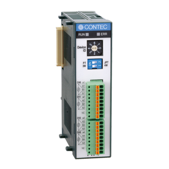
2. Module Nomenclature and Settings 2. Module Nomenclature and Settings Nomenclature of Module Components Figure 2.1. shows the names of module components. In the figure, the indicated switch settings represent factory settings. LED indicator Device Device ID Sensor setting SW Interface Connector PTI-4 Figure 2.1. -
Page 16: Led Indicator
2. Module Nomenclature and Settings LED Indicator Table 2.1. LED indicator Name Color LED indicator Green Comes on upon completion of startup after the power is turned on. Comes on upon disconnction detection or alarm output. Sensor setting SW The settings of the sensor setting switches can be read by software. Use the channel-1 and channel-2 switches to select the wiring method and the type of platinum resistance temperature detector to be used, respectively. -
Page 17: Connecting To An External Device
3. Connecting to an External Device 3. Connecting to an External Device Interface Connector How to Connect an Interface Connector When connecting the Module to an external device, use the attached connector plug. When wiring the Module, strip off approximately 7 - 8 mm of the covering for the cable, and insert the bare wire by pressing the orange button on the connector plug. -
Page 18: Connecting A Platinum Resistance Temperature Detector
3. Connecting to an External Device Connecting a Platinum Resistance Temperature Detector To connect a platinum resistance temperature detector, use the interface connector on the face of the module. Set the sensor setting switches according to the type of the platinum resistance temperature detector and its wiring method. -
Page 19: Using The I/O Address Map
4. Using the I/O Address Map 4. Using the I/O Address Map Starting I/O Address When connected to a CPU-SBxx(FIT)GY, the PTI-4(FIT)GY can directly receive I/O commands from the controller module. Depending on how the Device ID is set, the I/O addresses indicated below will be used exclusively by the PTI-4(FIT)GY. -
Page 20: List Of I/O Address Maps
4. Using the I/O Address Map List of I/O Address Maps Starting address Products Category (Input Only) Rivision Data (Input Only) Rivision Rivision Rivision Rivision (00h) Data 3 Data 2 Data 1 Data 0 Input Products ID Number (01h) Conversion setting Average Average Average... - Page 21 4. Using the I/O Address Map Channel selection Reserved Reserved Reserved Reserved Reserved Reserved Data1 Data0 (0Fh) CHx temperature data 1/3 (Input Only) DATA7 DATA6 DATA5 DATA4 DATA3 DATA2 DATA1 DATA0 (10h) CHx temperature data 2/3 (Input Only) DATA15 DATA14 DATA13 DATA12 DATA11...
- Page 22 4. Using the I/O Address Map CHx alarm output upper / upper limit 1/3 DATA7 DATA6 DATA5 DATA4 DATA3 DATA2 DATA1 DATA0 (20h) CHx alarm output upper / upper limit 2/3 DATA15 DATA14 DATA13 DATA12 DATA11 DATA10 DATA9 DATA8 (21h) CHx alarm output upper / upper limit 3/3 Sign bit DATA22...
-
Page 23: I/O Address Map Detailed Information
Figure 4.2. Product information Revision Data [D3 - D0]: This is product update information, subject to change without notice, that is managed by CONTEC. Product Category [D7 - D4]: This is a module function classification code. For the PTI-4(FIT)GY, the code is "2h". -
Page 24: Basic Function
4. Using the I/O Address Map Basic function Conversion setting Set basic operation states. Input Conversion setting Average Average Conversion Conversion Calibration Operation Reserved Reserved processing1 processing0 speed1 speed0 selection mode (02h) Figure 4.3. Conversion setting D0: Operation mode Set this bit to read the direct resistance value of the resistance temperature detector. Setting the bit to 1 selects the resistance mode. - Page 25 4. Using the I/O Address Map D4 - D5: Average processing selecting Set these bits to use the averaging function. You can choose from two types of averaging: averaging by time and averaging by count. The registers are used in combination with the +0Ah "averaging time/count setting" register. When the averaging function is used, the CHx temperature data registers from +13h to +15h store the temperature averaged by time or sampling count according to the "averaging time/count setting".
- Page 26 4. Using the I/O Address Map Average processing time / average processing count setting Average processing time / average processing count setting Data7 Data6 Data5 Data4 Data3 Data2 Data1 Data0 (0Ah) Figure 4.6. Average processing time / average processing count setting This setting stores the averaging count/time setting according to the setting of the +2h [conversion setting] register.
- Page 27 4. Using the I/O Address Map CHx temperature data (Input Only) CHx temperature data 1/3 (Input Only) DATA7 DATA6 DATA5 DATA4 DATA3 DATA2 DATA1 DATA0 (10h) CHx temperature data 2/3 (Input Only) DATA15 DATA14 DATA13 DATA12 DATA11 DATA10 DATA9 DATA8 (11h) CHx temperature data 3/3 (Input Only) Over...
-
Page 28: Alarm Output Function
4. Using the I/O Address Map Alarm output function If detecting the temperature different from the setting range, you can output to the alarm output register. The module can be programmed to take action only when the alarm output register changes without reading temperatures regularly. - Page 29 4. Using the I/O Address Map Current value of alarm output flag (Input Only) Current value of alarm output flag (Input Only) CH3 upper CH2 upper CH1 upper CH0 upper CH3 lower CH2 lower CH1 lower CH0 lower (0Ch) Figure 4.12. Current value of alarm output flag When the alarm output function for a given channel is enabled in the [alarm output enable] register, the corresponding alarm output flag is set to 1 the moment the input exceeds the upper / upper value or goes below the lower / lower value, which are specified at +20h and later and is set to 0 the moment the input...
- Page 30 4. Using the I/O Address Map CHx alarm output upper / upper limit, upper / lower limit, lower / upper limit and lower / lower limit CHx alarm output * / * limit 1/3 DATA7 DATA6 DATA5 DATA4 DATA3 DATA2 DATA1 DATA0 CHx alarm output * / * limit 2/3...
-
Page 31: Offset / Gain Settings Function
4. Using the I/O Address Map Offset / Gain settings function The offset and gain values can be set for each channel to correct errors. This function can be used for correcting temperature conversion according to the actual measurement environment. Setting the [calibration selection] bit in the [conversion setting] register to 1 enables the offset/gain setting function. - Page 32 4. Using the I/O Address Map 3. Calculate the gain value and write it to the [gain setting value] register. After writing the offset value, input the maximum temperature in the measured temperature range or its resistance equivalent to obtain the gain setting value from the following equation: Write the obtained value to the [gain setting value] register according to "CHx Offset and Gain Settings".
-
Page 33: Examples
4. Using the I/O Address Map Examples Software Mode Flowchart Following is a description of an example where the PTI-4(FIT)GY is installed at device ID: 0. Start Address : Output 0Ch to a base I/O address of +0Eh Conversion disable disables conversion of channels 2 and 3. - Page 34 4. Using the I/O Address Map outp( ADR+0x0E, convSet ); for( ch = 0; ch < 4; ch++ ){ outp( ADR+0x0F, ch ); inData =(unsigned long)inp( ADR+0x10 ); inData |=(unsigned long)inp( ADR+0x11 ) << 8; inData |=(unsigned long)inp( ADR+0x12 ) << 16; /* over check */ if( inData &...
-
Page 35: Using The Memory Address Map
5. Using the Memory Address Map 5. Using the Memory Address Map When connected to a CPU-CA10xx(FIT), the PTI-4(FIT)GY can be accessed by a host computer through a network. In addition, the Module can be allocated to the memory controlled by the Controller Module according to a given Device ID. -
Page 36: Module Settings Area
5. Using the Memory Address Map Module Settings Area A module settings area, which is a 128-byte (80h) area beginning with address 301000h and corresponding to a given Device ID, is where the settings for the given device are read and written. The starting address can be determined according to the following expression: Starting address = 301000h + 80h x (Device ID) Table 5.1. - Page 37 5. Using the Memory Address Map Table 5.1. Module setting area < 2 / 3 > Access Initial Initial Address (h) Area Item Size type value (h) settings Starting address+20 Conversion disable Conversion Starting address+21 Alarm output setting Starting address+22 Alarm output 000000 upper / upper limit...
- Page 38 5. Using the Memory Address Map Table 5.1. Module setting area < 3 / 3 > Access Initial Initial Address (h) Area Item Size type value (h) settings Starting address+68 Conversion disable Conversion Starting address+69 Alarm output setting Starting address+6A Alarm output 000000 upper / upper limit...
- Page 39 5. Using the Memory Address Map Module-specific information Module type (category) The PTI-4(FIT)GY belongs to the analog module (02h) category. Module type (serial No.) The PTI-4(FIT)GY is an analog module with a serial No. 4 (04h). Supported functions The PTI-4(FIT)GY supports the basic I/O function (03h). The basic input data takes temperature value.
- Page 40 5. Using the Memory Address Map Items Common to Modules Module startup register Setting the module startup (01h) register activate the module to start conversion of selected channels. 00h : Module stop (Conversion terminated) 01h : Module startup (Conversion in progress) Error status The error status bits, which are not reflected in the module settings area, always remain [00h].
- Page 41 5. Using the Memory Address Map Average processing setting Set this item to average temperature data by time or sampling count. Setting value Function 0 (00h)*1 No averaging 1 (01h) Average count 2 (02h) Average time *1 Factory setting Average processing value Set a value for the count or time set for averaging.
- Page 42 5. Using the Memory Address Map Chanel setting Conversion disable This item controls conversion of a given channel. Setting the data for a channel to "01h" disables the conversion of that channel, saving the update interval for the channel. 00h : Conversion (Factory setting) 01h : Conversion disable Alarm output setting This item selects whether to output an alarm depending on the temperature data value.
-
Page 43: Module Information Area
5. Using the Memory Address Map Module Information Area The module information area is a 128-byte (80h) area beginning with address 300000h and corresponding to a given Device ID. It is the area to read the setting. The starting address can be determined according to the following expression: Starting address = 300000h + 80h x (Device ID) Table 5.2. - Page 44 5. Using the Memory Address Map Table 5.2. Module information area < 2 / 2 > Access Initial Address (h) Area Item Size type value (h) Starting address+20 Conversion disable Starting address+21 Alarm output setting Starting address+22 Alarm output 000000 upper / upper limit - Starting address+24 Starting address+25...
- Page 45 5. Using the Memory Address Map When the module is started, the contents of the module setting area are stored in the module information area, with the exception of the [Module Startup Register] and the [Error Status]. Module startup register This register holds the module operating status.
-
Page 46: Basic I/O Data Area
5. Using the Memory Address Map Basic I/O Data Area The basic input data area, which is a 128-byte (80h) area beginning with address 304000h, corresponds to a given Device ID. The starting address can be determined according to the following expression: Starting address = 304000h + 80h x (Device ID) Table 5.3. - Page 47 5. Using the Memory Address Map Status flag Alarm / upper Alarm / lower Disconnction Alarm / upper Alarm / lower (Latch) (Latch) Figure 5.2. Status flag Alarm upper / lower (latch) The bit is set to "1" when input data exceeds the upper upper limit for alarm output or goes below the lower lower limit even once with the alarm output set to "01h".
- Page 48 5. Using the Memory Address Map Status flag Alarm upper Alarm lower (latch) (latch) Figure 5.3. Status flag Alarm upper / lower (latch clear) Setting the bit clears alarm latch data set in the basic input data area. The bit is set to 0 upon completion of latch clearing.
-
Page 49: Examples
5. Using the Memory Address Map Examples Flowchart Following is a description of an example where the PTI-4(FIT)GY is installed at device ID: 0 Start Open processing Open seccess? Is the module type Address : Reading the address 301000h identifies the category. analog? Analog module is "02h". - Page 50 5. Using the Memory Address Map Sample program /*=========================================================================== F&eIT I/F Sample Program DEVICE ID: Channel: 0 to 3ch ========================================================================== */ #include <windows.h> #include <stdio.h> #include <stdlib.h> #include <conio.h> #include "Fit.h" /* Address(common) */ #define FIT_IO (0x00300000) #define FIT_IO_DEVICE_INFOR (0x0000) #define FIT_IO_DEVICE_CONFIG (0x1000)
- Page 51 5. Using the Memory Address Map /* Offset Address dwVaOffset = FIT_IO_DEVICE_SIZE * FIT_SAMPLE_DEVICE_ID; /* Read 'Category' */ dwVaBase = FIT_IO + FIT_IO_DEVICE_CONFIG; wStatus = FIT_Read(hHandle, dwVaBase + dwVaOffset + FIT_PRODUCT_CATEGORY, 1, &byCategory); if (wStatus != 0) { printf("Error! FIT_Read = %04X(H)\n", wStatus); FIT_Close(hHandle);...
- Page 52 5. Using the Memory Address Map PTI-4(FIT)GY...
-
Page 53: System Reference
6. System Reference 6. System Reference Block Diagram Interface Connector CH0,CH1 Interface Connector CH2,CH3 Current Source Analog to Digital Conversion Photo Coupler Manual Setting Device ID Isolated DC/DC Controll Circuit Converter Sensor Setting Stack Connector Figure 6.1. Circuit block diagram PTI-4(FIT)GY... -
Page 54: Specifications
6. System Reference Specifications Table 6.1. Specifications Item Specifications Number of channel 4 channels Platinum resistance temperature Pt100(JIS C1604-1997, IEC 751 1983), JPt100(JIS C1604-1989) detectors acceptable Wiring method Three-wire or Four-wire Measurable temperature range Pt100 : -200 - 850°C JPt100 : -200 - 510°C Precision Operating temperature 0 - 50°C ±0.3°C *1... - Page 55 6. System Reference Table 6.2. Installation Environment Requirements Parameter Requirement description Operating temperature 0 - 50°C Storage temperature -10 - 60°C Operating humidity 10 - 90%RH (No condensation) Floating dust particles Not to be excessive Corrosive gases None Noise immunity Line noise *1 AC line/2kV, Signal line/1kV (IEC1000-4-4Level 3, EN61000-4-4Level 3)
-
Page 56: External Dimensions
6. System Reference External Dimensions (1.2) (1.2) Device PTI-4 25.2 64.7 [mm] Figure 6.2. External dimensions PTI-4(FIT)GY... -
Page 57: Appendix
6. System Reference Appendix Reference Resistances of Resistance Temperature Detectors Table 6.3. New JIS / IEC type (Pt100) Unit : Ω JIS C1604-1997, IEC 751 1983 -200 -100 Temp Temp [°C] [°C] 18.52 60.26 100.00 100.00 138.51 175.86 212.05 247.09 280.98 313.71 345.28 375.70 56.19 96.09 103.90 142.29 179.53 215.61 250.53 284.30 316.92 348.38 378.68 52.11 92.16... -
Page 58: Q&A
6. System Reference Q&A The ERR LED remains on immediately after the power is turned on. What's wrong? The ERR LED interlocks with the disconnction detection and alarm output functions. If any channel has no sensor connected or an incorrect Three-wire or Four-wire setting, the module detects disconnction and turns on the ERR LED. - Page 59 PTI-4(FIT)GY User’s Manual CONTEC CO., LTD. November 2006 Edition No part of this document may be copied or reproduced in any form by any means without prior written consent of CONTEC CO., LTD. [11152006] [12272004] Management No. A-46-818 [11152006_rev3] Parts No.
Need help?
Do you have a question about the PLUG-IN PTI-4GY and is the answer not in the manual?
Questions and answers