Advertisement
Quick Links
Package Contents
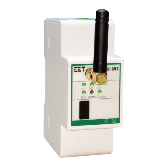
Meter Overview
Indicator
A
L1, L2, L3
Voltage Phase Active Indicator
B
Run
Device Running Status Indicator
C
-
Infrared Communication Port
D
-
E
Comm.
F
Alarm
Alarm/Energy Pulse Indicator
LED Indicator
Indicator
Color
L1/L2/L3
Green
Run
Green
Alarm
Red
Comm.
Green
Mounting the Meter
Before installation, make sure that the DIN rail is already in place
Move the installation clip at the back of the PMC-352 downward to the "unlock"
position
Align the top of the mounting channel at the back of the PMC-352 at an angle against
the top of the DIN rail as shown in figure right
Rotate the bottom of the PMC-352 towards the back while applying a slight pressure to
make sure that the device is completely and securely fixed on to the DIN rail
Push the installation clip upward to the "lock" position to secure the PMC-352 on to
the DIN Rail
PMC-352 Quick Start Guide
a. PMC-352 Meter with all installation clips and plug-in connectors installed
b. Factory Test Report
c. CD with PMC-352 User Manual
d. Quick Start Guide (this document)
Description
Antenna
Communication Indicator
Status
On
Off
All Off
Blink once per second
Off
Flashing
On
Flashing
Off
Version 1.0
July 24, 2020
Terminal
G
TC11, TC12, TC21, TC22, TC31, TC32, TC41, TC42
H
DIC, DI1, DI2, DI3
I
D+, D-
J
I11, I12, I21, I22, I31, I32
K
V1, V2, V3, VN
L
L/+, N/- (NC, NC for Self-Powered option)
Register 6040 is enabled and the corresponding Voltage Phase is active
Register 6040 is enabled and the corresponding Voltage Phase is inactive
Device is running normally
Power Off or Device is running abnormally
Energy Pulsing is enabled
Energy Pulsing is disabled and at least one Setpoint is Active
Receiving or transmitting data via RS-485 or LoRa
Description
Register 6040 is disabled
No Communication
Description
NTC Inputs
Digital Inputs
RS-485 Ports
Current Inputs
Voltage Inputs
Power Supply
Revision Date: July 24, 2020
Advertisement

Subscribe to Our Youtube Channel
Related Manuals for CET PMC-352


Summary of Contents for CET PMC-352
- Page 1 Move the installation clip at the back of the PMC-352 downward to the “unlock” position Align the top of the mounting channel at the back of the PMC-352 at an angle against the top of the DIN rail as shown in figure right ...
- Page 2 Wiring Diagrams 3P4W with 3CTs 3P3W with 3CTs 3P3W with 2CTs 3P4W with 3PTs, 3CTs 3P3W with 2PTs, 3CTs 3P3W with 2PTs, 2CTs 1P3W with 2CTs 1P2W Uln with 1CT 1P2W Ull with 1CT 3x1P with 3CTs Basic Setup Parameters Menu Parameters Description...
Need help?
Do you have a question about the PMC-352 and is the answer not in the manual?
Questions and answers