Sign In
Upload
Manuals
Brands
ADLINK Technology Manuals
Desktop
MVP-5002
ADLINK Technology MVP-5002 Manuals
Manuals and User Guides for ADLINK Technology MVP-5002. We have
1
ADLINK Technology MVP-5002 manual available for free PDF download: User Manual
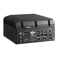
ADLINK Technology MVP-5002 User Manual (88 pages)
High Performance 6th Generation Intel Core i7/i5/i3 Fanless Computer
Brand:
ADLINK Technology
| Category:
Desktop
| Size: 4 MB
Table of Contents
Table of Contents
5
List of Tables
11
List of Figures
13
1 Introduction
15
Overview
15
Features
15
Specifications
16
Figure 1-1: MVP-5000 Functional Block Diagram
18
Schematics and Dimensions
19
Figure 1-2: Front View
19
Figure 1-3: Left Side View
20
Figure 1-4: Top View
21
Figure 1-5: Rear View
21
Figure 1-6: Underside View
22
Front Panel I/O Connectors
23
Figure 1-7: Front Panel
23
Displayport Connectors
24
LED Indicators
24
Power Button
24
Reset Button
24
Figure 1-8: Displayport Connector
24
Table 1-1: LED Indicators
24
Display Options
25
Table 1-2: Displayport Pin Assignments
25
Table 1-3: Applicable Cable Types
25
Digital I/O Connector
26
8-Channel Digital Input
26
8-Channel Digital Output
26
Table 1-4: Maximum Available Resolutions with 2-Display Configuration
26
Table 1-5: Digital Input Connector Pin Legend
27
Figure 1-9: Digital I/O Connector Pin Assignment
27
Table 1-6: Digital Output Connector Pin Legend
28
Figure 1-10: Digital Input Circuit
28
Figure 1-11: Digital Output Circuit
28
DVI-D Connector
29
Figure 1-12: DVI-D Connector Pin Assignment
29
Figure 1-13: VGA Connector Pin Assignment
29
Table 1-7: DVI-D Connector Pin Legend
29
VGA Connector
29
Gigabit Ethernet Ports
30
Table 1-8: VGA Connector Pin Legend
30
USB 2.0 Ports
30
Figure 1-14: Ethernet Port and LED Legend
31
Table 1-10: Speed LED Indicators
31
Table 1-9: Active/Link LED Indicators
31
DC Power Connector
32
Figure 1-15: DC Power Connector
32
Table 1-11: DC Power Supply Connector Signals
32
USB 3.0 Ports
32
COM Port Connectors
33
Rear-Mounted Cfast Host Connector
33
Table 1-12: D-Sub 9P Signal Function of COM Ports
33
Figure 1-16: COM Port
33
Figure 1-17: Cfast Host Connector (on Rear Panel)
34
Internal I/O Connectors
35
Figure 1-18: Mainboard I/O Connectors
35
Table 1-13: Mainboard Connector Legend
35
Figure 1-19: Cfast Board Connectors
36
GPS Module Power Header
36
Table 1-14: Cfast Board Connector Legend
36
GPS Module Power Headers
37
Mini Pcie Socket
37
SATA Connector
37
USB 2.0 Connector
37
Clear CMOS Jumper
38
Fan Connector
38
Figure 1-20: Clear CMOS Jumper Setting
38
Extended PWR/RESET Header
39
USIM Slot
39
2 Getting Started
41
Unpacking Checklist
41
Installing Hard Disk Drives
41
Installing Cfast Cards
45
Wall-Mounting the MVP-5000
47
Driver Installation
49
Adapter
50
A Appendix: Power Consumption
51
Power Consumption Reference
51
Table A-1: Power Consumption
51
B Appendix: BIOS Setup
53
Main
53
BIOS Information
54
Platform Information
54
FW Information
54
System Time/System Date
55
Advanced
55
CPU Configuration
56
Hyper-Threading
57
Active Processor Cores
57
Intel Virtualization Technology
57
Cpu Aes
57
Intel(R) Speedstep(Tm)
57
CPU C States
57
Intel TXT(LT) Support
57
TCC Activation Offset
57
Memory Configuration
58
System Agent (SA) Configuration
59
VT-D
59
Graphics Configuration
60
GTT Size
60
Aperture Size
60
DVMT Pre-Allocated
60
DVMT Total Gfx Mem
60
Onboard Device Configuration
61
Serial Port 1 to 4 Configuration
61
LAN #1 (Intel I211AT)
61
LAN #1(I211AT) Launch PXE Oprom
61
LAN #2 (Intel I211AT)
61
LAN #2(I211AT) Launch PXE Oprom
62
LAN #3 (Intel I211AT)
62
LAN #3(I211AT) Launch PXE Oprom
62
Serial Port Console Redirection
62
Advanced Power Management
63
State after G3
63
State after G3
64
RTC Wake System from S5
64
BIOS POST Watchdog
64
USB Configuration
64
Legacy USB Support
64
XHCI Hand-Off
65
USB Mass Storage Driver Support
65
Port 60/64 Emulation
65
USB Transfer Time-Out
65
Device Reset Time-Out
65
Device Power-Up Delay
65
SATA Configuration
66
SATA Port and Cfast Card
66
CSM Configuration
67
CSM Support
67
Gatea20 Active
67
Option ROM Messages
67
Boot Option Filter
67
Network
68
Storage
68
Video
68
Other PCI Devices
68
Network Stack Configuration
68
PC Health Status
69
Security
70
Administrator Password
70
User Password
70
RTC Lock
70
BIOS Lock
71
Boot
71
Setup Prompt Timeout
71
Bootup Num-Lock State
71
Quiet Boot
72
Fast Boot
72
Boot Option Priorities
72
Save & Exit
74
Discard Changes and Exit
74
Save Changes and Reset
74
Discard Changes
74
Restore Defaults
74
Save as User Defaults
75
Restore User Defaults
75
Launch EFI Shell from Filesystem Device
75
C Appendix: Watchdog Timer (WDT)
77
Function Library
77
WDT with Api/Windows
77
Awlwatchdoggetcount
77
Awlwatchdogsettrigger
77
D Appendix: Digital Input/Output
79
Function Library
79
DI/O with Api/Windows
79
Important Safety Instructions
83
Getting Service
87
Advertisement
Advertisement
Related Products
ADLINK Technology MVP-5100
ADLINK Technology MVP-5000 Series
ADLINK Technology MVP-5001
ADLINK Technology MVP-5003
ADLINK Technology MVP-510A
ADLINK Technology MVP-5101
ADLINK Technology MVP-5102
ADLINK Technology MVP-5103
ADLINK Technology MVP-5104
ADLINK Technology Value MVP-6220
ADLINK Technology Categories
Computer Hardware
Motherboard
PCI Card
Control Unit
Desktop
More ADLINK Technology Manuals
Login
Sign In
OR
Sign in with Facebook
Sign in with Google
Upload manual
Upload from disk
Upload from URL