Table of Contents
Advertisement
Quick Links
Advertisement
Table of Contents

Subscribe to Our Youtube Channel
Related Manuals for Advantech SOM-5885


Summary of Contents for Advantech SOM-5885
- Page 1 User Manual SOM-5885 CPU Computer on Module...
- Page 2 No part of this manual may be reproduced, copied, translated, or transmitted in any form or by any means without the prior written permission of Advantech Co., Ltd. The information provided in this manual is intended to be accurate and reliable.
- Page 3 This product has passed the CE test for environmental specifications when shielded cables are used for external wiring. We recommend the use of shielded cables. This type of cable is available from Advantech. Please contact your local supplier for ordering information.
- Page 4 Discard used batteries according to the manufacturer's instructions.” Note! Notes provide additional and/or optional information. Document Feedback To assist us with improving this manual, we welcome all comments and constructive criticism. Please send all feedback in writing to support@advantech.com. Selection Guide Including Part Numbers Max. Base Default...
- Page 5 Do not touch any components on the CPU card or other cards while the PC is powered on. Disconnect the power before making any configuration changes. A sudden rush of power after connecting a jumper or installing a card may damage sensitive electronic components. SOM-5885 User Manual...
- Page 6 In accordance with IEC 704-1:1982 specifications, the sound pressure level at the operator’s position should not exceed 70 dB (A). DISCLAIMER: This set of instructions is given according to IEC 704-1. Advantech disclaims all responsibility for the accuracy of any statements contained herein.
-
Page 7: Table Of Contents
1.3.10 Power Management..............9 1.3.11 Environment................10 1.3.12 MTBF ..................10 1.3.13 OS Support ................. 11 1.3.14 Advantech iManager ..............11 1.3.15 Power Consumption..............11 Table 1.9: Power Consumption Table (Watts)......11 1.3.16 Performance ................11 1.3.17 Pin Description................12... - Page 8 Figure 3.36System Agent (SA) Configuration ......57 Figure 3.37Memory Configuration ..........58 Figure 3.38Graphics Configuration..........59 Figure 3.39VMD Setup Menu ............. 60 3.5.2 PCI Express Configuration ............61 Figure 3.40PCI Express Configuration ........61 Figure 3.41PCIE clocks .............. 62 SOM-5885 User Manual viii...
- Page 9 Other OS..................76 Advantech iManager ................77 Appendix A Pin Assignment .........79 SOM-5885 Pin Assignment..............80 Table A.1: SOM-5885 Pin Assignments ........80 Appendix B Watchdog Timer ........87 Programming the Watchdog Timer ............88 Table B.1: Programming the Watchdog Timer......88...
- Page 10 SOM-5885 User Manual...
-
Page 11: Chapter 1 General Information
Chapter General Information This chapter details background information on the SOM-5885 CPU Computer on Module. Sections include: Introduction Functional Block Diagram Product Specifications... -
Page 12: Introduction
Introduction SOM-5885 is a COM Express Type 6 Basic Module with a 14th Gen Intel® Core™ processor. It delivers octa-core computing performance with a 45W TDP, while pro- viding IXe LPG graphics, and Advantech’s Edge AI Suite software toolkit. SOM-5885 supports up to 96GB DDR5 5600 RAM, offering a 1.7x increase in com- puting performance and 1.5x increase in 3D graphics performance compared to pre-... - Page 13 Serial Presence Detect – refers to serial EEPROM on DRAMs that has DRAM Module configuration information Trusted Platform Module – a chip to enhance the security features of a com- puter system UEFI Unified Extensible Firmware Interface Watch Dog Timer SOM-5885 User Manual...
-
Page 14: Functional Block Diagram
Functional Block Diagram SOM-5885 User Manual... -
Page 15: Product Specifications
Trusted Platform Module 0 / 1 (TPM_PP) Serial Serial Ports 1 - 2 0 / 2 Serial CAN interface on SER1 0 / 1 Serial SPI (Devices) 1 / 2 Serial SMBus 1 / 1 Serial 1 / 1 SOM-5885 User Manual... -
Page 16: Processor System
Core® Ultra 5-125U 1.3GHz/0.8GHz 4.3GHz 12-28W 1.3.4 Memory There are a total of 2 memory sockets on the SOM-5885. The topside has 2 by default. This solution supports max 96GB capacity (non-ECC memory modules with all SKUs.) with 260-pin SODIMM sockets (dual-channel). 1.3.5 Graphics/Audio Graphics Core: Intel®... -
Page 17: Expansion Interfaces
(x1, x2, x4) (16.0 GT/s), 1 x PCIe x1 Gen4 and 3 x PCIe x1 Gen3 (8.0 GT/s) specifi- cations. Several configurable combinations may need BIOS modification. Please contact Advantech sales or FAE for more details. Table 1.6: PCI Express... -
Page 18: I/O
USB 4.0 / USB 3.2 / USB 2.0 SOM-5885 supports 2 x USB 4.0, 4 x USB 3.2 Gen2 (10 Gbps) ports and 8 x USB 2.0 (480 Mbps) ports which are reverse compatible to USB 1.x. For USB 3.2, it sup- ports LPM (U0, U1, U2, and U3) for power efficiency. -
Page 19: Power Management
SPI_CS0# to Carrier Board, SPI_CS1# to Module SPI_CS0# to Module, SPI_CS1# to Carrier Board Note: If system COMS is cleared, Advantech strongly suggests going to the BIOS setup menu and loading the default settings on the first boot-up. The standard module has no jumper at SW1, so BIOS settings are kept without an RTC coin battery. -
Page 20: Environment
1.3.10.5 Advantech S5 ECO Mode (Deep Sleep Mode) Advantech iManager provides additional features allowing the system to enter a very low suspended power mode – S5 ECO mode. In this mode, the module will cut all power, including suspended and active power to the chipset, and keep an on-module controller active. -
Page 21: Os Support
1.3.13 OS Support The mission of Advantech Embedded Software Services is to "Enhance quality of life with Advantech platforms and Microsoft Windows Embedded technology." We enable Windows Embedded software products on Advantech platforms to more effectively support the embedded computing community. Customers are freed from the hassle of dealing with multiple vendors (hardware suppliers, system integrators, embedded OS distributors) for projects. -
Page 22: Pin Description
1.3.17 Pin Description Advantech provides useful checklists for schematic design and layout routing. The schematic checklist will specify details about each pin’s electrical properties and how to connect it in different scenarios. The layout checklist will specify the layout con- straints and recommendations for trace length, impedance, and other necessary information during design. -
Page 23: Chapter 2 Mechanical Information
Chapter Mechanical Information This chapter details mechanical information for the SOM-5885 CPU Computer on Module. Sections include: Board Information Mechanical Drawings Assembly Drawings... -
Page 24: Board Information
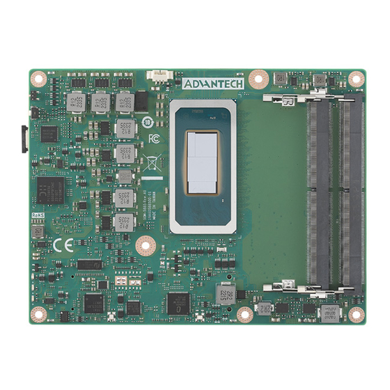
Board Information The figures below demonstrate the main chips on the SOM-5885 Computer-on-Mod- ule. Be aware of these positions when designing your customer’s carrier board to avoid mechanical damage and to improve thermal dissipation performance. 14th G Intel® Core™ Ultra Processor... -
Page 25: Mechanical Diagram
Mechanical Diagram For more details regarding 2D/3D models, please visit the Advantech COM support service website: http://com.advantech.com. Figure 2.3 Board Mechanical Diagram – Front Figure 2.4 Board Mechanical Diagram – Rear SOM-5885 User Manual... - Page 26 Figure 2.5 Board Mechanical Diagram – Side 1 Figure 2.6 Board Mechanical Diagram – Side 2 SOM-5885 User Manual...
-
Page 27: Assembly Diagram
These figures demonstrate the order of assembly needed when attaching the thermal module and COM module to the carrier board. Figure 2.7 Assembly Diagram There are 5 x reserved screw holes for the SOM-5885 used to assemble the heat spreader. SOM-5885 User Manual... -
Page 28: Assembly Diagram
Assembly Diagram Consider the CPU and chip height tolerance when designing your thermal solution. Figure 2.8 CPU Height and Tolerance SOM-5885 User Manual... -
Page 29: Chapter 3 Ami Bios
Chapter AMI BIOS This chapter details BIOS setup information for the SOM-5885 CPU Computer on Module. Sections include: Introduction Entering Setup Hot/Operation Keys Exit BIOS Setup Utility... -
Page 30: Introduction
This information is stored in flash ROM so it retains the Setup information when the power is turned off. Entering Setup Turn on the computer and then press <DEL> or <ESC> to enter the Setup menu. SOM-5885 User Manual... -
Page 31: Main Setup
System Date using the <Arrow> keys. Enter new values through the keyboard. Press the <Tab> key or the <Arrow> keys to move between fields. The date must be entered in MM/DD/YY format. The time must be entered in HH:MM:SS format. SOM-5885 User Manual... -
Page 32: Advanced Bios Features Setup
Configure Intel® Active Management Technology Parameters. Trusted Computing Trusted Computing Settings. ACPI Settings ACPI Sleep State. SMART Settings System SMART Settings. Embedded Controller Embedded Controller Parameters. Serial Port Console Redirection Console Redirection Settings. SOM-5885 User Manual... -
Page 33: Rc Acpi Settings
PCIE Access Method is Direct I/O or ACPI. Native PCIE Enable Bit-PCIe Native*control 0-~Hot Plug 1-SHPC Native Hot Plug control 2-2-~Power Management Events 3-3-PCIe Advanced Error Reporting control 4-4-PCIe Capability Structure control 5-Latency Tolerance Reporting control SOM-5885 User Manual... - Page 34 (Mutually exclusive with Smart connect). While this is enabled, it also disables 8524 timer for SLP_S0 support. PCI Delay Optimization Experimental ACPI additions for FW latency optimizations. MSI enabled When disabled, MSI support is disabled in FADT. PCIe delay between_OFF_ON PCIe delay between _OFF _ON. SOM-5885 User Manual...
-
Page 35: Cpu Configuration
3.4.2 CPU Configuration Figure 3.5 CPU Configuration Figure 3.6 CPU Configuration Efficient-core Information Displays the E-core Information. SOM-5885 User Manual... - Page 36 ‘Disabled’ as well. This option will be grayed out when ’VT-d’ option is config- ured as ‘Disabled’. Legacy Game Compatibility Mode When enabled, pressing the scroll lock key will toggle the Efficient-cores between being parked when Scroll Lock LED is on and un-parked when the LED is off. SOM-5885 User Manual...
- Page 37 Figure 3.7 Efficient-core Information Figure 3.8 Performance-core SOM-5885 User Manual...
-
Page 38: Power & Performance
3.4.3 Power & Performance Figure 3.9 Power & Performance CPU - Power Management Control CPU - Power Management Control Options. GT/Media - Power Management Control GT/Media - Power Management Control Options. SOM-5885 User Manual... - Page 39 EPP. Disable EPP grouping autonomous will not necessarily request same values for all cores with same EPP. HwP Lock Enable/Disable HWP Lock support in Misc Power Management MSR. Turbo Mode Enable/Disable processor Turbo Mode. SOM-5885 User Manual...
- Page 40 When set, it will map IO_read instuctions sent to IO registers PMG_IO_BASE_ADDRBASE+offset to MWAIT(offset). Package C State Limit Maximum Package C State Limit Setting. Cpu Default: Leaves it as Factory default value. Auto: Initializes to deepest available Package C State Limit. SOM-5885 User Manual...
- Page 41 Enable/Disable the Energy Efficient Turbo Feature. This feature will opportunis- tically lower the turbo frequency to increase efficiency. It is recommended only to disable it in overclocking situations where turbo frequency must remain con- stant. Otherwise, leave enabled. SOM-5885 User Manual...
- Page 42 Figure 3.12 Current Turbo Ratio Limit Settings Figure 3.13 Config TDP Configurations Enable Configurable TDP Applies cTDP (Assured Power) initialization settings based on non-cTDP (Assured Power) or cTDP (Assured Power). Default is 1: Applies to cTDP SOM-5885 User Manual...
- Page 43 Processor Base Power (TDP) value should be main- tained. ConfigTDP Turbo Activation Ratio Custom value for Turbo Activation Ratio. It needs to be configured with valid val- ues from LFM to Max Turbo. 0 means it is not using a custom value. SOM-5885 User Manual...
- Page 44 Maximum GT frequency limited by the user. Choose between 2400MHx (RPN) and 6900MHz (RP0). A value beyond the range will be clipped to the min/max supported by the SKU. Disable Turbo GT frequency Enabled: Disable Turbo GT frequency. Disabled: GT frequency is not limited. SOM-5885 User Manual...
-
Page 45: Pch-Fw Configuration
Enable/Disable FD0 Shipment State Override. The BIOS will override the soft strap setting when enabled. Firmware Update Configuration Configure Intel(R) Active Management Technology Parameters. Extend CSME Measurement to TPM-PCR Enable/Disable Extend CSME Measurement to TPM-PCR[0] and AMT Config to TPM-PCR[1]. SOM-5885 User Manual... -
Page 46: Acpi D3Cold Settings
USB RTD3 support disabled. For SawtoothPeak USB Port1 (Below) is Superspeed and Port2 (Top) is HighSpeed. Check the respective board configu- ration to see the USB port position. USB Port 1 USB RTD3 support. Super Speed: USB 3.0 devices will be exposed as RTD3 SOM-5885 User Manual... - Page 47 PCIe RTD3 setup conflicts with SATA RTD3. Platform specific. PCIe Remapped CR2 PCIe RTD3 setup conflicts with SATA RTD3. Platform specific. PCIe Remapped CR3 PCIe RTD3 setup conflicts with SATA RTD3. Platform specific. RTD3 Support for PCIE Rootports Enable/Disable PCIE RTD3 Support. SOM-5885 User Manual...
-
Page 48: Amt Configuration
ASF Configuration Configure Alert Standard Format parameters. Secure Erase Configuration Secure Erase configuration menu. One Click Recovery(OCR) Configuration Configuration setting for One Click Recovery. This allows access for AMT to boot a recovery IS application. SOM-5885 User Manual... - Page 49 Figure 3.18 ASF Configuration PET Process Enable/Disable PET Events Progress to receive PET Events. WatchDog Enable/Disable the WatchDog Timer. ASF Sensors Table Adds the ASF Sensor Table into the ASF! ACPI Table. SOM-5885 User Manual...
- Page 50 Figure 3.19 Secure Erase Configuration Secure Erase mode Change Secure Erase module behavior: Simulated: Performs SE flow without erasing SSD Real: Erase SSD. Force Secure Erase Force Secure Erase on next boot. SOM-5885 User Manual...
- Page 51 OCR PBA Boot Enable/Disable One Click Recovery PBA Boot. OCR Windows Recovery Boot Enable/Disable One Click Recovery Windows Recovery Boot. OCR Disable Secure Boot Allows CSME to request SecureBoot to be disabled for One Click Recovery. SOM-5885 User Manual...
-
Page 52: Trusted Computing
TPM 1.2 will restrict support to TPM 1.2 devices; TPM 2.0 will restrict support to TPM 2.0 devices; Auto will support both with default set to TPM 2.0 devices; if not found, TPM 1.2 devices will be enumerated. SOM-5885 User Manual... -
Page 53: Acpi Settings
3.4.8 ACPI Settings Figure 3.22 ACPI Settings Enable ACPI Auto Configuration Enable or Disable BIOS ACPI Auto Configuration. Enable Hibernation ACPI Sleep State. SOM-5885 User Manual... -
Page 54: Smart Settings
3.4.9 SMART Settings Figure 3.23 SMART Settings SMART Self Test Run SMART Self Test on all HDDs during POST. SOM-5885 User Manual... -
Page 55: Embedded Controller
Serial Port 2 Configuration Set Parameters of Serial Port 2 (COMB). Hardware Monitor Monitor hardware status. ACPI Report Method Configuration Select ACPI Reporting Method for EC Devices. CAN0 Control Enable/Disable CAN0 controller on RDC-IS200. SOM-5885 User Manual... -
Page 56: Serial Port Console Redirection
3.4.11 Serial Port Console Redirection 3.4.11.1 Serial Port 1 Configuration Figure 3.25 Serial Port 1 Configuration Serial Port Enable or Disable Serial Port (COM). Change Settings Select an optimal settings for a Super IO Device. SOM-5885 User Manual... - Page 57 3.4.11.2 Serial Port 2 Configuration Figure 3.26 Serial Port 2 Configuration Serial Port Enable or Disable Serial Port (COM). Change Settings Select optimal settings for a Super IO Device. SOM-5885 User Manual...
- Page 58 Figure 3.27 Serial Port Console Redirection COM1 Console Redirection Console Redirection Enable or Disable. COM2 Console Redirection Console Redirection Enable or Disable. Console Redirection EMS Console Redirection Enable or Disable. SOM-5885 User Manual...
- Page 59 Figure 3.28 Console Redirection Settings SOM-5885 User Manual...
-
Page 60: Pci Subsystem Settings
Otherwise -> Reported vendor _HID. (Driver installation is necessary.) ACPI Report Method for GPIO Select the ACPI reporting method for EC GPIO. PNP0C02 -> Reported as reserved motherboard resource. Otherwise -> Reported vendor _HID. (Driver installation is necessary.) SOM-5885 User Manual... -
Page 61: Usb Configuration
Maximum time the device will take before it properly reports itself to the Host Controller. 'Auto' uses the default value: for a Root port it is 100 ms, for a Hub port the delay is taken from the Hub descriptor. SOM-5885 User Manual... -
Page 62: Network Stack Configuration
Wait time in seconds to press ESC key to abort the PXE boot. Use either +/- or numeric keys to set the value. Media detect count Number of times presence of media will be checked. Use either +/- or numeric keys to set the value. SOM-5885 User Manual... -
Page 63: Nvme Configuration
3.4.15 NVMe Configuration Figure 3.32 NVMe Configuration SOM-5885 User Manual... -
Page 64: Dual Bios Configuration
Manually switch BIOS flash to boot up. Auto mode allows BIOS flash to be switched by SUSI/SW. BIOS Fail Awaiting Timing Determine specific timing to monitor if BIOS hasn’t yet booted up successfully; then BIOS will be switched to another one. SOM-5885 User Manual... -
Page 65: Intel® Ethernet Controller I226-Lmvp
3.4.17 Intel® Ethernet Controller I226-LMvP Figure 3.34 Intel® Ethernet Controller I226-LMvP SOM-5885 User Manual... -
Page 66: Chipset Setup
Chipset Setup Figure 3.35 Chipset Setup System Agent (SA) Configuration System Agent Parameters. PCIE Configuration PCIE Parameters. PCH-IO Configuration PCH Parameters. SOM-5885 User Manual... -
Page 67: System Agent (Sa) Configuration
Graphics Configuration VMD setup menu VMD Configuration. VT-d VT-d capability. Above 4GB MMIO BIOS assignment Enable/Disable above 4GB memory-mapped IO BIOS assignment. This is enabled automatically when aperture size is set to 2048MB. SOM-5885 User Manual... - Page 68 Size to set HOB Buffer. Max TOLUD Maximum value of TOLUD. Dynamic assignment will adjust TOLUD automati- cally based on the largest MMIO length of the installed graphics controller. Fast Boot Enable/Disable fast path through the MRC. SOM-5885 User Manual...
- Page 69 Select which of IGFX/PEG/PCI Graphics devices should be the Primary Display Or select HG for Hybrid Gfx. Internal Graphics Keep IGFX enabled based on the setup options. DVMT Pre-Allocated Select DVMT5.0 pre-allocated (fixed) Graphics Memory size used by the inter- nal graphics device. SOM-5885 User Manual...
- Page 70 RAID5 Enable/Disable RAID5 feature. RAID10 Enable/Disable RAID10 feature. Intel Rapid Recovery Technology RRT volumes can span internal and eSATA drivers Intel(R) Optane(TM) Memory Enable/Disable System Acceleration with the Intel(R) Optane(TM) Memory fea- ture. SOM-5885 User Manual...
-
Page 71: Pci Express Configuration
PCIE Root Port 0 PCIE Root Port 1 PCIE Root Port 2 PCIE Root Port 3 On board LAN PEG Root Port 8-11 PEG Root Port 12-15 PEG Root Port 0-7 SOM-5885 User Manual... - Page 72 Platform-POR = CLKREQ signal is assigned to CLKSRC according to board layout. Disabled = CLKREQ will not be used. Clock4 assignment Platform-POR = clock is assigned to PCIe port or LAN according to board lay- out. Enabled=keep clock enabled even if unused. Disabled=Disable clock. SOM-5885 User Manual...
- Page 73 Platform-POR = CLKREQ signal is assigned to CLKSRC according to board layout. Disabled = CLKREQ will not be used. Figure 3.42 PCIE Root Port PCI Express Root Port PXPD Control the PCI Express Root Port. SOM-5885 User Manual...
- Page 74 Spin up Device SATA Device Type Identify if the SATA port is connected to a Solid State Drive or Hard Disk Drive. Topology SATA Port 0 DevSlp DIT0 Configuration Enable/Disable DIT0 Configuration. SOM-5885 User Manual...
- Page 75 Selectively Enable/Disable the corresponding USB port from reporting a Device Connection to the controller. USB SW Device Mode Port #0 Enable Connector Event for device subscription. USB SW Device Mode Port #1 Enable Connector Event for device subscription. SOM-5885 User Manual...
- Page 76 Enable/Disable the PCH BIOS lock enable feature. it is required to be enabled to ensure SMM protection of flash. Force unlock on all GPIO pads If Enabled, BIOS will force all GPIO pads to be in an unlocked state. SOM-5885 User Manual...
- Page 77 HD Audio Subsystem Configuration Settings Figure 3.46 HD Audio Subsystem Configuration Settings HD Audio Control Detection of the HD-Audio device. Disabled=HDA will be unconditionally disabled. Enabled=HDA will be unconditionally enabled. Audio DSP Enable/Disable Audio DSP. SOM-5885 User Manual...
-
Page 78: Pch-Io Configuration
Enable 8254 Clock Gate Lock PCH Sideband Access Flash Protection Range Registers (FPRR) SPD Write Disable Enable/Disable setting SPD Write Disable. For security recommendations, the SPD write disable bit must be set. LGMR SOM-5885 User Manual... -
Page 79: Security Chipset
Security Chipset Figure 3.48 Security Chipset Administrator Password Set Setup Administrator Password. User Password Set User Password. Secure Boot Secure Boot Configuration. SOM-5885 User Manual... -
Page 80: Secure Boot
System is in User mode. The mode change requires a plat- form reset. Secure Boot Mode Secure Boot mode options: Standard or Custom. In Custom mode, Secure Boot Policy variables can be configured by a physi- cally present user without full authentication. SOM-5885 User Manual... -
Page 81: Boot Setup
Number of seconds to wait for setup activation key. 65535(0xFFFF) means indefinite waiting. Bootup NumLock State Select the keyboard NumLock state. Quiet Boot Enables or disables the Quiet Boot option. Boot Option #1 Sets the system boot order. SOM-5885 User Manual... -
Page 82: Save & Exit
Restore/Load Default values for all the setup options. Save as User Defaults Save the changes done so far as User Defaults. Restore User Defaults Restore the User Defaults to all the setup options. Boot Override SOM-5885 User Manual... -
Page 83: Mebx
MEBx Figure 3.52 MEBx SOM-5885 User Manual... - Page 84 SOM-5885 User Manual...
-
Page 85: S/W Introduction & Installation
Chapter S/W Introduction & Installation S/W Introduction Driver Installation Advantech iManager... -
Page 86: S/W Introduction
S/W Introduction The mission of Advantech Embedded Software Services is to “Enhance quality of life with Advantech platforms and Microsoft Windows embedded technology”. We enable Windows Embedded software products on Advantech platforms to more effectively support the embedded computing community. Customers are freed from the hassle of dealing with multiple vendors (Hardware suppliers, System integrators, Embedded OS distributors) for projects. -
Page 87: Advantech Imanager
It makes these embedded features easier to integrate, speed up develop- ing schedule, and provide the customer’s software continuity while upgrade hard- ware. More detail of how to use the APIs and utilities, please refer to Advantech iManager2.0 Software API User Manual. - Page 88 SOM-5885 User Manual...
-
Page 89: Appendix A Pin Assignment
Appendix Pin Assignment This appendix gives you the infor- mation about the hardware pin assignment of the SOM-5885 CPU System on Module. Sections include: SOM-5885 Type 6 Pin Assign- ment... -
Page 90: Som-5885 Pin Assignment
This section gives SOM-5885 pin assignment on the COM Express connector which is compliant with COMR.0 R3.1 Type 6 pin-out definitions. For more details about how to use these pins and to obtain a design reference, please contact Advantech for a design guide, checklist, reference schematic, and other hardware/software support. - Page 91 Table A.1: SOM-5885 Pin Assignments USB4+ USB5+ GND (FIXED) GND (FIXED) USB2- USB3- USB2+ USB3+ USB_2_3_OC# USB_0_1_OC# USB0- USB1- USB0+ USB1+ VCC_RTC ESPI_EN# RSMRST_OUT# GBE0_SDP SYS_RESET# LPC_SERIRQ CB_RESET# GND (FIXED) GND (FIXED) PCIE_TX5+ PCIE_RX5+ PCIE_TX5- PCIE_RX5- GPI0 GPO1 PCIE_TX4+ PCIE_RX4+...
- Page 92 Table A.1: SOM-5885 Pin Assignments eDP_HPD VCC_5V_SBY PCIE_CLK_REF+ BIOS_DIS1# PCIE_CLK_REF- GND (FIXED) GND (FIXED) SPI_POWER SPI_MISO GPO0 SPI_CLK SPI_MOSI TPM_PP SPI_CS# SER0_TX GP_SPI_MISO SER0_RX GP_SPI_CK A100 GND (FIXED) B100 GND (FIXED) A101 SER1_TX B101 FAN_PWMOUT A102 SER1_RX B102 FAN_TACHIN A103...
- Page 93 Table A.1: SOM-5885 Pin Assignments PCIE_RX7- PCIE_TX7- DDI1_HPD N/A(*Note) N/A(*Note) DDI1_PAIR0+ N/A (*Note) DDI1_PAIR0- N/A (*Note) N/A(*Note) DDI1_PAIR1+ N/A(*Note) DDI1_PAIR1- GND (FIXED) GND (FIXED) DDI2_CTRLCLK_AUX+ DDI1_PAIR2+ DDI2_CTRLDATA_AUX- DDI1_PAIR2- DDI2_DDC_AUX_SEL DDI1_DDC_AUX_SEL N/A(*Note) RSVD DDI3_CTRLCLK_AUX+ DDI1_PAIR3+ DDI3_CTRLDATA_AUX- DDI1_PAIR3- DDI3_DDC_AUX_SEL DDI3_PAIR0+ DDI2_PAIR0+ DDI3_PAIR0-...
- Page 94 Table A.1: SOM-5885 Pin Assignments GND (FIXED) GND (FIXED) PEG_RX6+ PEG_TX6+ PEG_RX6- PEG_TX6- PEG_RX7+ PEG_TX7+ PEG_RX7- PEG_TX7- PEG_RX8+ PEG_TX8+ PEG_RX8- PEG_TX8- GND (FIXED) GND (FIXED) PEG_RX9+ PEG_TX9+ PEG_RX9- PEG_TX9- PEG_RX10+ PEG_TX10+ PEG_RX10- PEG_TX10- PEG_RX11+ PEG_TX11+ PEG_RX11- PEG_TX11- GND (FIXED) GND (FIXED)
- Page 95 C25 could be an optional pin reserved for SML0_CLK. Please contact FAE for details. C26 could be an optional pin reserved for SML0_DAT. Please contact FAE for details. C27 could be an optional pin reserved for SML1_CLK. Please contact FAE for details. SOM-5885 User Manual...
- Page 96 D47 could be an optional pin reserved for USB4_2_SSTX1-. Please contact FAE for details. D49 could be an optional pin reserved for USB4_2_SSRX1+. Please contact FAE for details. D50 could be an optional pin reserved for USB4_2_SSRX1-. Please contact FAE for details. SOM-5885 User Manual...
-
Page 97: Appendix B Watchdog Timer
Appendix Watchdog Timer This appendix details information about the watchdog timer pro- gramming on the SOM-5885 CPU System on Module. Sections include: Watchdog Timer Programming... -
Page 98: Programming The Watchdog Timer
BIOS, and then sets it to EC. Only Win10 supports this. In other OS, it will still use an IRQ number from the BIOS settings as usual. For details, please refer to the iManager & Software API User Manual. SOM-5885 User Manual... -
Page 99: Appendix C Programming Gpio
Appendix Programming GPIO This Appendix illustrates the Gen- eral Purpose Input and Output pin settings. Sections include: GPIO Register... -
Page 100: Gpio Register
Table C.1: GPIO Register GPIO Byte Mapping H/W Pin Name BIT0 GPI0 BIT1 GPI1 BIT2 GPI2 BIT3 GPI3 BIT4 GPO0 BIT5 GPO1 BIT6 GPO2 BIT7 GPO4 For details, please refer to the iManager and Software API User Manual. SOM-5885 User Manual... -
Page 101: Appendix D System Assignments
Appendix System Assignments This appendix gives you informa- tion about the system resource allocation on the SOM-5885 CPU System on Module. Sections include: System I/O Ports DMA Channel Assignments Interrupt Assignments 1 MB Memory Map... -
Page 102: System I/O Ports
Programmable interrupt controller 0x00000030-0x00000031 Programmable interrupt controller 0x00000034-0x00000035 Programmable interrupt controller 0x00000038-0x00000039 Programmable interrupt controller 0x0000003C-0x0000003D Programmable interrupt controller 0x000000A0-0x000000A1 Programmable interrupt controller 0x000000A4-0x000000A5 Programmable interrupt controller 0x000000A8-0x000000A9 Programmable interrupt controller 0x000000AC-0x000000AD Programmable interrupt controller 0x000000B0-0x000000B1 Programmable interrupt controller SOM-5885 User Manual... -
Page 103: Interrupt Assignments
IRQ 4294967291 Intel® Management Engine Interface #1 IRQ 0 System timer IRQ 32 Intel® Serial IO I2C Host Controller - 7E78 IRQ 14 Intel® Serial IO GPIO Host Controller - INTC1083 IRQ 4294967293 PCI Express Root Port SOM-5885 User Manual... -
Page 104: 1St Mb Memory Map
Intel® Serial IO GPIO Host Controller - INTC1083 0xE0D40000-0xE0D4FFFF Intel® Serial IO GPIO Host Controller - INTC1083 0xE0D50000-0xE0D5FFFF Intel® Serial IO GPIO Host Controller - INTC1083 0xBFFBC000-0xBFFBFFFF Intel® Smart Sound Technology BUS 0xBFC00000-0xBFDFFFFF Intel® Smart Sound Technology BUS SOM-5885 User Manual... - Page 105 SOM-5885 User Manual...
- Page 106 No part of this publication may be reproduced in any form or by any means, such as electronically, by photocopying, recording, or otherwise, without prior written permission from the publisher. All brand and product names are trademarks or registered trademarks of their respective companies. © Advantech Co., Ltd. 2024...
Need help?
Do you have a question about the SOM-5885 and is the answer not in the manual?
Questions and answers