Table of Contents
Advertisement
Advertisement
Table of Contents

Related Manuals for Fnirsi FNB48


Summary of Contents for Fnirsi FNB48
- Page 1 FNB48 User Manual (V0.6)
-
Page 2: Table Of Contents
Catalog 0.0 Versions and Updates ..........................4 1.0 Overview ..............................4 2.0 Safety Precautions ..........................4 3.0 Performance description ........................5 3.0.1 Interface ..............................5 3.0.2 Human-computer interaction ......................5 3.0.3 Voltage and Current ..........................5 3.0.4 Fast charge trigger ..........................5 3.0.5 Wire identification class ........................ - Page 3 8.0 Quick charge protocol trigger and detection menu ..............18 8.0.1 Fast charge protocol automatic detection ................... 19 8.0.2 QC2.0 Trigger ............................19 8.0.3 QC3.0 Trigger ............................20 8.0.4 Huawei FCP trigger ..........................20 8.0.5 Huawei SCP trigger ..........................20 8.0.6 Samsung AFC trigger .........................
-
Page 4: Versions And Updates
0.0 Versions and Updates As instrument products have many functions and frequent software and hardware updates, the manual may be updated at any time, please be aware. Please get the latest update information on the official website. 1.0 Overview The FNB48USB tester is a high-reliability, high-safety USB voltage and current detection meter and a mobile communication terminal fast charging trigger. -
Page 5: Performance Description
3.0 Performance description 3.0.1 Interface 1 Input monitoring port: USB-A, 9-PIN male; 2 Input monitoring port: TYPE-C, 24-PIN female seat; 3 Input monitoring port: Micro-USB, 5-PIN female socket; 4 output monitoring ports: USB-A, 9-PIN female socket; 5 Output monitoring port: TYPE-C, 24-PIN female socket; 6 PC connection port: Micro-USB, 5-PIN female socket. -
Page 6: Wire Identification Class
4 PD2.0/3.0 Trigger; 5 VOOC/WARP Trigger; 6 SuperVOOC Trigger; 7 The above protocols all support automatic monitoring 8 MTK-PE automatic detection; 9 Support QC2.0->PD2.0 protocol conversion; 10 Support a maximum of 24 hours for a limited time trigger, and automatically close the trigger when the time comes 3.0.5 Wire identification class 1 The internal resistance measurement of the wire by the differential pressure method;... -
Page 7: Structure Appearance
4.0 Structure appearance 1 Input monitoring port: USB-A, 9-PIN male; 2 Input monitoring port: TYPE-C, 24-PIN female socket; 3 input monitoring port: Micro-USB, 5-PIN female socket; 4 output monitoring port: TYPE-C, 24-PIN female socket; 5 PD communication switch 6 output monitoring port: USB-A, 9-PIN female;... -
Page 8: Technical Index
5.0 Technical index Accuracy: ±(a%(‰) reading + number of words) Index Range Resolution Accuracy Monitor voltage 4~24V 0.00001V ±(0.2‰+2) Monitor current 0~6.5A ±(0.5‰+2) 0.00001A Monitor power 0~156W ±(0.5‰+2) 0.00001W Load equivalent internal 0~9999.9Ω 0.0001Ω ±(0.5‰+2) resistance D+/D- voltage 0~3.3V ±(1.0%+2) 0.001V ℃... -
Page 9: Main Page
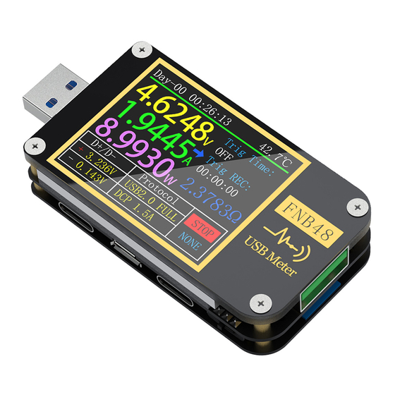
6.0 Main page Except for special instructions, the left and right buttons switch pages/menus, the middle button confirms, and the BACK button cancels/returns.Long press the BACK button to turn off the screen backlight, all pages are valid. 6.0.1 Concise page Description Only the three key parameters of voltage, current and power are displayed, →... -
Page 10: Record Page
6.0.2 Record page Descri ption The top row of data from left to right are boot record time and onboard temperature respectively; The uppercase data on the left is voltage, current, and power from top to bottom; The curve and progress bar on the right are the remaining storage capacity of the voltage and current curves;... -
Page 11: Fast Charge Recognition Page
6.0.3 Fast charge recognition page Description The top row of data from left to right are boot record time and onboard temperature respectively; The uppercase data on the left is voltage, current, and power from top to bottom; The trigger time limit on the right is the setting menu -> trigger ->... -
Page 12: Curve Display Page
6.0.4 Curve display page Description From left to right: Mode 1: Low-speed voltage and current curve. Mode 2: Low-speed D+D- curve. Mode 3: Record offline curve. Mode 4: High-speed voltage ripple (AC coupling). Instructions (1) Long press the left button: time base minus. (2) Click the middle button: start/pause drawing the curve. -
Page 13: Wire Resistance Measurement Page
6.0.5 Wire resistance measurement page Description FNB48 uses the differential pressure method to measure the internal resistance of the cable, which needs to be used with a constant current load. (1) Click the middle button: use the current voltage and current... -
Page 14: Record Function Expansion
7.0 Record function expansion 7.0.1 Energy statistics list Description In the record page (6.0.2), long press the left button to enter. Each line in the list represents a group of parameters, from left to right are group number, capacity, energy, the selected group is displayed in green, and the lower left corner is the selected group Statistics time, the lower right corner is the group number of the current statistics group. -
Page 15: Battery Capacity Calculation Tool
7.0.2 Battery capacity calculation tool Description In the record page (6.0.2), press and hold the right button to enter. Select the statistics group,Set battery voltage, energy conversion efficiency, The battery capacity can be calculated.Click the middle button to move the green dot on the left between Group, BattVol and ConvEff. -
Page 16: Quick Charge Protocol Trigger And Detection Menu
8.0 Quick charge protocol trigger and detection menu Description On the (6.0.3) fast charge recognition page, long press the left button and confirm to enter.. This meter supports QC2.0/QC3.0, HuaWeiFCP/SCP, SamsungAFC trigger, VOOC/DASH constant pressure mode, PD2.0/3.0 trigger, and QC2.0->PD2.0 protocol conversion Note Once you enter the quick charge trigger/detection... -
Page 17: Fast Charge Protocol Automatic Detection
8.0.1 Fast charge protocol automatic detection In this mode,The meter tries to trigger various protocols in turn,Display the test results on the screen,Red is not supported,Green is support,In the process of testing,Such as measuring PD chargers,It is normal to restart and continue testing.During the test, it is forbidden to connect to any equipment at the back end. -
Page 18: Qc3.0 Trigger
8.0.3 QC3.0 Trigger In QC3.0 trigger mode,Use the left and right keys to decrease/increase the trigger voltage,Click BACK to return.Press the left/right keys to quickly decrease/increase the voltage. 8.0.4 Huawei FCP trigger The operation method is the same as QC2.0 trigger. 8.0.5 Huawei SCP trigger The operation mode is the same as QC3.0 trigger 8.0.6 Samsung AFC trigger... -
Page 19: Pd Protocol Trigger
8.0.7 PD Protocol trigger Switch the PD communication switch to ON, Enter the PD protocol trigger mode. After exiting the PD trigger, switch the PD communication switch to OFF. Take the picture as an example. The picture shows a message sent by a charger.There are 6 gears in total, of which gears 1, 2, 3, 4, and 5 are fixed voltage gears.The sixth gear is the adjustable voltage gear (PPS). -
Page 20: Vooc/Warp Constant Voltage Trigger
8.0.9 VOOC/WARP Constant voltage trigger The operation method is the same as QC3.0 trigger. 8.0.9 SVOOC Trigger SuperVOOC requires a load greater than 500mA on the back end to deceive, And SuperVOOC only has a voltage of 10.5V,Therefore, you can only press BACK to return to the page, and there is no other operation. -
Page 21: Charging Tool
9.0 Charging tool On the (6.0.3) fast charge identification page, long- click the right button to enter the charging tool menu. The functions are: 1 PD monitor. 2 Read the E-Marker cable. 3 Read the DASH cable. 4 Analog DASH cable. 5 Apple 2.4A acceleration. - Page 22 Click the middle button,Can switch to the page of "View detailed communication process",As shown above.Left column,You can select the message to be viewed by left/key,Such as: Now select the message of 410x1882REQ<-. is the message number, In this instrument, the larger the message number, the newer the message.0x1882 is the message header.REQ is the message type,Represents this is a request (Request) message,The request message (Request) is used to apply to the charging head for the gear required for charging (for example, it is 6 gears...
-
Page 23: Read E-Marker Cable
9.0.2 Read E-Marker cable E-Marker cable refers to a cable with an E-Marker chip in the Type-C interface,If the interface does not contain E-Marker chip,The packets from the PD charging head cannot exceed 3A current,And only use the E-Marker cable to trigger the PD protocol,The current can exceed 3A. -
Page 24: Read Dash Cable
VOOC/WARP flash charge. If,The phone normally needs to use a USB-A->Type-C DASH cable,But there is no such thread in hand,Only FNB48 tester and a C-C cable,But want to trigger VOOC/WARP flash charge,At this time, the function of simulating DASH cable can be started,And use the C-C cable to connect to the phone, You can perform VOOC/WARP flash charging. -
Page 25: Setting Menu
10.0 Setting menu Description In the settings menu,Left click and right click to select menu options,Click the middle button to enter/confirm the current option,Click the BACK button to return/cancel/exit the current option/menu. 10.1 Settings menu->General Set up some general system configurations. 10.1.1 Display brightness Set the screen brightness, the adjustable range is 1-20. -
Page 26: Settings Menu -> Record
10.1.7 Current change wake up Set the wake-up current,When the current change exceeds the wake-up current,The meter changes from standby state to normal working state,When set to 0, this function is turned off. 10.1.8 Bluetooth switch After closing, Bluetooth data transmission is not possible 10.1.9 Gravity direction recognition When opened,Automatically switch page orientation,After closing,Unable to automatically switch the page reverse,But you can switch the page... -
Page 27: Settings Menu -> System
10.3.1 Trigger time Set trigger time. 10.3.2 Block PD CDC After opening,When PD is monitoring,CRC messages can be masked,Off by default. 10.3.2 Boot simulation DASH After it is turned on, turn on the analog DASH cable function at boot, which is turned off by default. 10.3.2 Boot Apple 2.4A After opening,Turn on the Apple 2.4A acceleration function when booting, Off by default.
Need help?
Do you have a question about the FNB48 and is the answer not in the manual?
Questions and answers