Advertisement
Advertisement
Table of Contents

Related Manuals for Fnirsi LCR-P1


Summary of Contents for Fnirsi LCR-P1
- Page 1 LCR-P1 晶体管检测仪 TRANSISTOR TESTER...
- Page 3 目 录...
- Page 4 CATALOG...
- Page 5 用户须知 ●本手册详细介绍了产品的使用方法、 注意事项以及相关事项, 在 使用产品之前, 请详细阅 读手册, 以便发挥产品的最佳性能。 ●不要在易燃、 易爆的环境中使用仪器。 ●仪器更换的废旧电池和报废的仪器不可与生活垃圾一同处理请 按国家或者当地的相关 法律规定处理。 ●当仪器出现任何质量问题或者对使用仪器有疑问时, 可联系 “菲 尼瑞斯-FNIRSI” 在线客服或厂家, 我们将在第一时间为您解决。 一、 产品简介 晶体管检测仪LCR-P1是一款高精度、 多功能的电子测试设备, 专为 电子工程师、 技术人员和电子爱好者设计。 该设备旨在检测和分析 晶体管、 二极管、 三极管、 场效应管 (FET) 等半导体元件的性能和特 性。 配备彩屏, 能够多元器件的多参数测量, 自动识别被测元件的类 型及引脚排列, 简化操作流程, 提高测试效率。...
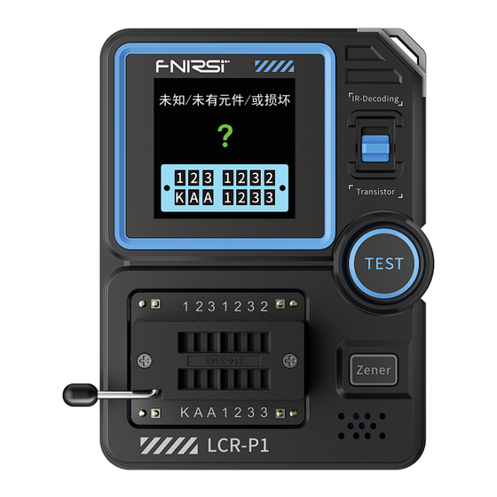
- Page 6 二、 面板介绍 充电/数据传输 充电指示灯 屏幕 模式切换拨杆 开机/测试键 高压键 红外接收器 锁紧座 (123晶体管测试区域, KAA稳压二极管测试区域)...
- Page 7 三、 参数介绍 【 3.1 】 主机参数 产品型号 LCR-P1 显示屏 1.44寸 电池容量 300mAH锂电池 充电规格 USBType-C, 5V/1A 产品尺寸 71×87×28mm 【 3.2 】 元器件测试参数 类目 说明 范围 放 大 倍 数 h f e, 基 极 ﹣ 发 射 极 压 Ube,Ic/le, 集电极﹣发射极反向截...
- Page 8 类目 范围 说明 ·栅极电容Cg,Vgs下的漏极电流ld, 保护二极管正向压降Uf JFET ·Vgs下的漏极电流ld, 保护二极管 场效应管 IGBT 正向压降Uf ·开启电压Vt, 栅极电容Cg, 漏源电 MIOSTET 阻Rds, 保护二极管正向压降Uf 单向可控硅 开启电压<5V 门极电压 门极触发 双向可控硅 电流<6mA 电容 25pF~100mF 电容值, 损耗系数Vloss, 内阻ESR 电阻 0.01Ω-50MΩ 电阻值 电感 10uH-1000uH 电感值, 直流电阻 电池 0.1-4.5V 电压值, 正负极性 显示用户码和数据码, 并显示对应 红外遥控...
- Page 9 四、 操作说明 【 4.1 】 开关机 开机:关机状态下按TEST键进入测试界 面 未知/未有元件/或损坏 关机: 在非测量页面长按TEST键关机 【 4.2 】 电容、 电阻、 电感、 二极管、 电池测试等两脚元器件测试 元器件引脚插入两个不同位号的测试孔 (1、 3或1、 2或2、 3) ,下压锁紧 杆, 按TEST键进行测试, 会测量结束会显示对应的测试参数几及引 脚顺序...
- Page 10 【 4.3 】 三极管、 MOS管等三脚元器件测试 三个引脚分别插入1、 2、 3位号测试孔, 下压锁紧杆, 按TEST键进行 测试会测量结束会显示对应的测试参数以及引脚顺序 【 4.4 】 稳压二极管测试 按Zener键, 进入稳压二极管测试模式, 稳压二极管正极插入A位号 测试孔, 负极插入K位号测试孔(接反测试有插反提示)下压锁紧杆, 按TEST键进行测试会显示对应的测量结果...
- Page 11 【 4.5 】 红外解码 上拨模式切换拨杆, 进入红外解码测 试模式, 对准红外接收器发送红外信 号, 机器会自动进行解码, 解码完成 后显示地址码和用户码以及波形 五、 固件升级 ●关机状态下依次长按Zener键 (高压键) 和TEST键 (开机键) 进入 固件升级界面 ●通过Type-C线连接电脑 ●选择固件和当前设备的COM号, 点击开始升级 ●升级成功自动重启...
- Page 12 固件更新中 update 设备升级界面 连接电脑界面 六、 注意事项 ●未给电容放电直接测量在插入锁紧瞬间机器会给电容放电产生 火花。 该功能只是起到防止忘记放电保护作用, 正确使用还是建 议先给电容手动放电在测试。 ●在非测量过程中, 123锁紧接口属于导通状态, 禁止电池直接插 入。 ●测量元器件参数不在测试范围测试结果可能会出现非正确元器 件类型。...
- Page 13 七、 生产信息 产品名称: 晶体管检测仪 品牌/型号: FNIRSI/LCR-P1 服务电话: 0755-28020752 服务邮箱: support@fnirsi.com 商务邮箱: business@fnirsi.com 生产商: 深圳市菲尼瑞斯科技有限公司 地址: 广东省深圳市龙华区大浪街道伟华达工业园C栋西边8楼 网址: www.fnirsi.cn 执行标准: SJ/T 10333-1993...
-
Page 14: Notice To Users
●If there are any quality issues with the instrument or if you have any questions about its use, please contact "FNIRSI" online customer service or the manufacturer. We will resolve your issue promptly. -
Page 15: Panel Introduction
2.Panel Introduction Charging Charging / Indicator Data Transmission Mode Selection Screen Switch Power On / Test Button High Voltage Button Infrared Receiver Locking Seat (123 transistor testing area, KAA voltage regulator diode testing area) -
Page 16: Parameter Introduction
3.Parameter Introduction 【 3.1 】 Host parameters Product Model LCR-P1 Display Screen 1.44 inches Battery Capacity 300mAh lithium battery Charging Specification USB Type-C, 5V/1A Product Size 71×87×28mm 【 3.2 】 Component Test Parameters Category Range Explanation DC current gain hfe, base-emitter... - Page 17 Category Range Explanation ·Gate capacitance Cg, drain current Id at Vgs, forward voltage drop of protective JFET diode Uf. ·Id at Vgs, forward voltage drop of Field-Effect IGBT protective diode Uf. Transistor ·Threshold voltage Vt, gate capacitance MIOSTET Cg, drain-source resistance Rds, forward voltage drop of protective diode Uf.
- Page 18 4.Operating Instructions 【 4.1 】 Power On / Power Off Power On: Press the TEST button while in the power-off state to enter the testing interface. Power Off: Long press the TEST button on any non-measurement screen to power off. 【...
- Page 19 【 4.3 】 Testing of Three-pin Components such as Transistors, MOSFETs, etc Insert the three pins into test holes numbered 1, 2, and 3 respectively. Press down and lock the clamping rod, then press the TEST button to initiate testing. Upon completion of the measurement, the corresponding test parameters and pin sequence will be displayed.
- Page 20 【 4.5 】 Infrared Decoding Switch the mode selection switch upward to enter Infrared decoding test mode. Aim the device at the Infrared receiver send Infrared signal. The device will automatically decode the signal. After decoding, it will display the address code, user...
-
Page 21: Firmware Update
5.Firmware Update ● Power off the device, then press and hold the Zener button (high voltage button) followed by the TEST button (power button) to enter the firmware upgrade interface. ●Connect to a computer via Type-C cable. ●Select the firmware and COM port of the current device, then click 'Start Upgrade'. - Page 22 6.Precautions ●When measuring capacitors without prior discharge, sparks may occur at the moment of insertion and locking, which can discharge the capacitor. This function serves as a safety measure to prevent forgetting to discharge capacitors before testing. However, it is still recommended to manually discharge capacitors before testing for proper usage.
- Page 23 By the way, we have created an interesting community, welcome to contact FNiRSl staff to join our community. Shenzhen FNIRSI Technology Co., LTD. Add.: West of Building C , Weida Industrial Park , Dalang Street , Longhua District , Shenzhen , Guangdong , China Tel:...
Need help?
Do you have a question about the LCR-P1 and is the answer not in the manual?
Questions and answers