Table of Contents
Advertisement
Advertisement
Table of Contents

Related Manuals for Fnirsi DSO-TC2


Summary of Contents for Fnirsi DSO-TC2
- Page 1 O s cil los cop e Transi sto r Tes ter DSO-TC2...
-
Page 3: Table Of Contents
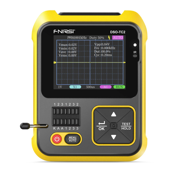
CATALOG 1、 Safety Instructions 2、 Product Introduction 3、 Technical Parameter 3.1 FNIRSI DSO-TC2 equipment parameters 3.2 Specifications of oscilloscope mode 3.3 Technical parameters of transistor detector 4、 Button & Interface 4.1 Button function 4.2 Transistor test socket 4.3 Signal interface 4.4 Charging interface... -
Page 4: 1、 Safety Instructions
When there is any quality problem with the instrument or when there is a question about using the instrument,You can contact "Finiris-FNIRSI" online customer service or the manufacturer,We will solve it for you as soon as possible �、... -
Page 5: 3、 Technical Parameter
�、 TECHNICAL PARAMETER 【3.1】 FNIRSI DSO-TC2 Equipment Parameters Display 2.4 inch TFT color screen, LED backlight Powered by 1500mAh rechargeable lithium battery Charging USB Type-C, +5V Size L79*W31*H103mm Bracket Hidden Support frame 【3.2】 Specifications Of Oscilloscope Mode The oscilloscope has a real-time sampling rate of 2.5MS/s and a 200kHz... -
Page 6: Technical Parameters Of Transistor Detector
Trigger type Rising edge, falling edge Trigger level Adjustable, with indication Waveform freeze Yes (HOLD function) Automatic Maximum, minimum, average, rms, peak-to-peak, measurement frequency, period, duty cycle PWM output FRQ: 0~80KHz, Duty cycle: 0~100%, Amplitude: 5.0V 【3.3】 Technical Parameters Of Transistor Detector This instrument can automatically identify and measure various transistors.Including NPN and PNP transistors, N-channel and P-channel field effect transistors, junction field effect transistors, diodes, double diodes,... -
Page 7: 4、 Button & Interface
Turn-on voltage SCRS <5V, gate trigger Gate voltage Triac current <6mA Capacitance 25pF~100mF Capacitance value, loss factor Vloss ⑤ Resistance 0.01Ω~50MΩ resistance Inductance 10uH~1000uH Inductance value, DC resistance ⑥ Battery 0.1~4.5V Voltage value, positive and negative polarity Input voltage 0~16V Voltage value DS18B20 Temperature... -
Page 8: Transistor Test Socket
Function Description Operate Button Digital Oscilloscope Transistor Tester Test mode selection Short Press Long Press Auto-adjustment rate below 20Hz Short Press cannot be calibrated correctly Enter or exit Enter the calibration confirmation the system interface - press the OK button to enter Long Press the calibration mode(long press AUTO again to cancel the calibration) -
Page 9: Signal Interface
There is a locking lever on the left end of the socket.The socket is relaxed when standing up.Insert or remove the component under test at this time.When turned down, the socket is locked and tested After inserting the element under test and locking.Press 【TEST】 button to test.The tester automatically identifies the pin name of the component and the test point where it is located, and displays it on the screen When testing 2-pin components, it can be inserted into any two holes with... -
Page 10: 5、 Oscilloscope Mode Features
【4.4】 Charging Interface The instrument is powered by a built-in lithium battery.There is a USB Type-C charging port on the bottom.Connect to 5V charger for charging The indicator light is solid red when charging, and the indicator light is solid green when fully charged In order to avoid static electricity damage to the instrument NOTE! -
Page 11: Oscilloscope Probe
Vertical sensitivity.Indicates the voltage represented by one grid in the vertical direction 1X/10X mode indicator icon.This must be consistent with the 1X/10X switch setting on the probe handle.If the probe is in 1X gear, then the oscilloscope should also be set to 1X gear.1X measures ±40V voltage, 10X measures ±400V voltage Horizontal time base.Indicates the length of time represented by one grid in the horizontal direction... - Page 12 �、 TRANSISTOR TESTER MODE FEATURES 【6.1】 Operation And TFT Display After entering this mode, the test will start automatically.Displays the internal Lithium battery voltage in the "Testing" state After the test results come out, you can click the 【TEST】 button to perform the next test at any time Operating Internal supply...
- Page 13 (6) The turn-on voltage of the thyristor should be less than 5V.In addition, the trigger current for maintaining conduction must be less than 6mA,other wise it cannot be measured correctly (7) The vLoss displayed when measuring the capacitance means loss and ...
-
Page 14: 7、 Extended Testing Capabilities
【6.5】 System Settings Press 【MENU】 button in TC2 component tester mode.It will enter the setting menu page, press the direction 【Up】 and 【Down】 buttons to select the tem.Press 【 OK】 to adjust parameters or switch states The items that can be set are as follows: (1)... -
Page 15: 8、 Firmware Upgrade
(3) PWM Output: adjustable frequency and duty cycle, output from the top MCX jack 【PWM】 (4) Zener Diode: Use the test seat K-A-A area for testing.See description in 【6.3】 (5) DS18B20: Follow the on-screen instructions to insert the temperature ... -
Page 16: 9、 Common Problem
(2) MM UPGRADE (Transistor Detector) a. Use the Type-C data cable with D+ and D- to connect the meter and the computer in the off state b. Press and hold the down arrow key, turn it on, wait for about 2s, and ... - Page 17 4: Why is the measured mains 220V waveform not a very standard sine wave, with distortion? A: The mains power grid is generally polluted and contains more high-order harmonic components.The superposition of these harmonics on the sine wave will show a distorted sine, which is a normal phenomenon. Generally,the mains waveform is distorted and has nothing to do with the oscilloscope itself 5: Why is there no signal input,The baseline (OV) on the...
-
Page 18: 11、 Production Information
10.When calibrating,The BNC probe needs to be unplugged, or the positive and negative poles of the probe are short-circuited ��、 PRODUCTION INFORMATION Product name: Oscilloscope Transistor Tester Brand / Model: FNIRSI / DSO-TC2 Manufacturer: Shenzhen FNIRSI Technology Co., Ltd. Website: www.fnirsi.cn Address: Building C, Weihuada Industrial Park, Dalang Street, Longhua District,... - Page 20 w w w . f n i r s i . c n...
Need help?
Do you have a question about the DSO-TC2 and is the answer not in the manual?
Questions and answers