Sign In
Upload
Manuals
Brands
turck Manuals
Control Unit
TBPN-L1-FDIO1-2IOL
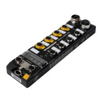
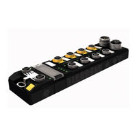
turck TBPN-L1-FDIO1-2IOL Block I/O Module Manuals
Manuals and User Guides for turck TBPN-L1-FDIO1-2IOL Block I/O Module. We have
3
turck TBPN-L1-FDIO1-2IOL Block I/O Module manuals available for free PDF download: User Manual, Safety Manual
turck TBPN-L1-FDIO1-2IOL User Manual (166 pages)
Safety Block I/O Module
Brand:
turck
| Category:
Control Unit
| Size: 3 MB
Table of Contents
Table of Contents
13
V01.00| 2017/04
13
V01.00| 2017/04
15
1 About this User Manual
17
General
17
Documentation Concept
17
Target Groups of this Operating Instruction
17
Further Information
18
Manufacturer and Service
19
2 Safety
21
Introduction
21
Intended Use
21
General Notes Regarding the Use of the Device
21
Residual Risks (en ISO/ISO 12100-1)
22
Foreseeable Misuse
22
Proper and Safe Operation
22
Notes Concerning Planning/Installation of this Product
22
Warranty and Liability
22
Directives and Standards
23
National and International Directives and Standards
23
Cited Standards
23
3 Product Description
25
General Product Description
25
Device Structure
26
Device Dimensions
27
Block Diagram
27
Connection Options at Device
28
Profinet
28
Power Supply
28
I/O Channels
29
Address Switches
30
Technical Data
31
Safety Characteristic Data
31
General Technical Data
31
Technical Data - Safety Inputs
33
Technical Data - Safety Outputs
34
Derating Curves
35
Safe I/O Channels
35
Safe Status
35
Fatal Error
35
Safety Inputs (FDI)
36
Safety Outputs (FDO)
38
Universal Standard I/Os
39
IO-Link Master Channels
39
3.10 Configuration Memory
39
Storing a Configuration
39
Loading a Configuration from the Memory Chip
40
Reset the Device to Factory Settings (Incl. Deleting the Memory Chip)
40
Deleting the Memory Chip
41
Module Behavior/Configuration Transfer
42
4 Mounting and Connecting
43
Mounting
43
Mounting Material
43
Mounting the Device
43
Grounding/Shielding Concept
44
Grounding the Device (FE)
45
Connection
46
Supply (PELV)
46
Connect the Supply Voltage 7/8
46
Connect the M12 Connectors
47
Assure Protection Class (IP67/IP69K)
48
5 Address Setting
49
F-Address Assignment
49
Address Setting in PROFINET
50
PROFINET Name
50
IP Address
50
6 Commissioning the Device
51
Initial Commissioning
51
Mounting/Electrical Installation
51
Configuring in Turck Safety Configurator
51
Operation of the Device at the PLC
52
7 Configuring with Turck Safety Configurator
53
Installing the Software
53
Integrate Turck Safety Configurator in Tia/Step7
53
Licensing the Software
54
Software Incensing for Virtual Machines (VM)
54
Starting the Software
54
Setting up a New Configuration
55
Adapting the Monitor Settings
56
Set up a Standard Configuration
58
Standard Configuration
59
Checking the Configuration
59
Loading the Configuration into the Safety Module
60
Change Password
60
7.10 Checking the Configuration
60
Loading the Diagnostics Configuration
62
7.11 Customize the Configuration
62
Customizing a Standard Application (Preliminary Considerations)
62
Set up an Own Configuration
64
Deleting Ossds
65
Add Emergency Shutdown in 64. OSSD
67
Light Grid (AOPD) in 63. OSSD
67
Switch on Non-Safety Channels Permanently (1. and 2. OSSD)
69
Switch off of FDX4/5 if Emergency Shutdown or Light Grid Activated
70
Switch off FDX6/7 at C3 (4. OSSD), if Output FDX4/5 Is Switched
72
Release of the Safety Function Via a Release Bit in the F-CPU
73
Adding the Device Via GSDML
74
Setting the F_Parameters
76
8 Operating
77
LED Displays
77
Error LED (ERR)
77
Bus-Led
78
Channel-Leds
78
Status and Control Word
80
Status Word
80
Control Word
80
Reset Device to Factory Settings
80
Device Behavior
80
Mapping
81
Process Input Data - Safe I/O Channels
82
Process Input Data - Universal Standard I/Os
85
Process Input Data - IO-Link Master Channels
86
Process Output Data
87
Overview - Entire Module
87
Process Output Data - Safe I/O Channels
89
Process Output Data - Universal Standard I/Os
91
9 Restarting after Device Exchange/Modification
93
Changing a TBPN-L1-FDIO1-2IOL
93
Prerequisites
93
Dismounting the Device to be Exchanged
93
Mounting the Exchange Device
93
Putting the Exchange Device into Operation
93
Disposing Devices
93
10 Maintenance, Repair, Decommissioning and Disposal
95
10.1 Maintenance
95
10.2 Repair
95
10.3 Decommissioning
95
10.4 Disposal
95
11 Glossary of Terms
97
Table of Contents
102
1 About this User Manual
104
Documentation Concept
104
Target Groups of this Operating Instruction
104
Further Information
104
Explanation of Symbols
105
Manufacturer and Service
105
2 Properties of the Universal Standard I/O Channels (DXP Channels)
106
General
106
Power Supply of the DXP Channels
107
Safe Shutdown of the DXP Channels
107
Technical Data, DXP Channels
107
Wiring Diagram
108
In- and Outputs, Pin Assignment C4 and C5
108
Process Data of the DXP Channels
109
Process Image TBPN-L1-FDIO1-2IOL
109
Parameters
111
Diagnostics/Status
111
LED Displays
111
Diagnostic Messages
111
Table of Contents
115
1 About this User Manual
117
Documentation Concept
117
Target Groups of this Operating Instruction
117
Further Information
117
Explanation of Symbols
118
Manufacturer and Service
118
2 IO-Link
119
IO-Link - the Fieldbus Independent Communication Interface
119
General Technical Information
119
Data Transmission
120
Transmission Media
120
Fieldbus/Ethernet Integration
121
3 Properties of the IO-Link Channels
123
General
123
Device Structure
123
Power Supply of the IO-Link Ports
124
Class A/B Supply
124
Safe Shutdown of IOL2 (at C7)
124
Technical Data
125
Wiring Diagrams
126
Process Data of the IO-Link Master Channels
127
Process Image TBPN-L1-FDIO1-2IOL
127
Parameters
131
Adaptation of the Process Data Mapping
136
Diagnostics/Status
137
LED Displays Channel Leds (C4 to C5)
137
Diagnostic Data
138
3.11 IO-Link and Turck Device Dtms
142
Topology-Scan
142
3.12 FSU - Fast Start-Up
142
Specific Configuration of the IO-Link Ports Via GSDML (SIDI)
143
4 IO-Link Data Storage
145
General
145
Parameter "Data Storage Mode" = Activated
146
Parameter "Data Storage Mode" = Read in
147
Parameter "Data Storage Mode" = Overwrite
148
Parameter "Data Storage Mode" = Deactivated, Clear
148
5 IO-Link - Functions for Acyclic Communication
149
General
149
Port Functions for Port 0 (IO-Link Master)
149
Subindex 64: Master Port Validation Configuration
149
Subindex 66: Set Default Parameterization
150
Subindex 67: Teach Mode
150
Subindex 68: Master Port Scan Configuration
151
6 The IO-Link Function Block IOL_CALL
155
General
155
IOL_CALL in Accordance with IO-Link Specification
155
Input Variables
156
Output Variables
156
STATUS - Communication Error Status
156
Iol_Status
156
7 Appendix
161
Start-Up: IO-Link-Device with IO-Link V1.0
161
Start-Up: IO-Link-Device with IO-Link V1.1
162
Start-Up Problems - Frequently Failure Causes
164
Advertisement
turck TBPN-L1-FDIO1-2IOL User Manual (125 pages)
Safety Block I/O Module
Brand:
turck
| Category:
I/O Systems
| Size: 7 MB
Table of Contents
Table of Contents
3
Tbpn-L
7
About These Instructions
10
Target Groups
10
Explanation of Symbols Used
10
Additional Documents
10
Feedback about These Instructions
11
Notes on the Product
11
Product Identification
11
Scope of Delivery
11
Turck Service
11
For Your Safety
12
Intended Use
12
Reasonably Foreseeable Misuse
12
General Safety Notes
13
Residual Risks (en ISO 12100:2010)
13
Warranty and Liability
13
Directives and Standards
14
National and International Directives and Standards
14
Cited Standards
14
Notes on Ex Protection
14
ATEX and Iecex Approval Requirements for Use in Ex Area
15
Product Description
16
Device Overview
16
Type Label
17
Properties and Features
17
Switches and Connectors
18
Functions and Operating Modes
19
Safety Function
19
Safety Inputs (FDI)
19
Safety Outputs (FDO)
20
Universal Standard I/Os
20
IO-Link Master Channels
20
Configuration Memory
20
Installing
21
Installing the Device in Zone 2 and Zone 22
21
Mounting Onto a Mounting Plate
22
Grounding the Device
22
Equivalent Wiring Diagram and Shielding Concept
22
Shielding of the Fieldbus and I/O Level
23
Grounding the Device - I/O Level and Fieldbus Level
23
Connecting
25
Connecting the Device in Zone 2 and Zone 22
25
Connecting the M12 Connectors
26
Connecting the Device to Ethernet
27
Connecting the Power Supply
28
Supply (SELV/PELV)
30
Connecting Safe Sensors and Actuators
31
Switching Examples
33
Inputs
33
Outputs
34
Commissioning
35
Initial Commissioning
35
Mounting and Electrical Installation
35
Configuring in Turck Safety Configurator
35
Commissioning the Device at the PLC
35
Safety Planning
35
Prerequisites
35
Reaction Time
36
Safety Characteristic Data
36
Addressing the Device
37
Setting the F Address at the Device
37
Addressing the Device at PROFINET
37
Configuring
39
Installing Turck Safety Configurator
39
Integrate Turck Safety Configurator in TIA Portal
39
Licensing Turck Safety Configurator
40
Creating a Configuration with the TSC Commissioning Wizard
41
Creating a New Workspace
41
Selecting a Master and Creating a Basic Configuration
41
Adapting the Configuration of the Safe Channels
44
Loading the Configuration with the TSC Commissioning Wizard
48
Application Example - Configuring a Safety Function in TSC
54
Checking and Loading the Configuration
59
Configuring Single Channel Safety Sensors
60
Configuring the Device at Profinet/Profisafe in TIA Portal
64
Adding the Device Via GSDML
64
Operating
67
LED Displays
67
Status- and Control Word
68
Process Input Data
69
Overview - Complete Module
69
Process Input Data - Safe I/O Channels
70
Process Output Data
74
Overview - Complete Module
74
Process Output Data - Safe I/O Channels
74
Using the Configuration Memory
76
Storing a Configuration
76
Loading a Configuration from the Memory Chip
76
Deleting the Memory Chip (Erase Memory)
76
Configuration Transfer and Module Behavior
77
Restarting after Device Exchange or Modification
79
Changing a Device
79
10.1.1 Prerequisites for Device Replacement
79
10.1.2 Procedure for Device Replacement
79
Maintenance
80
Decommissioning
80
Disposal
80
Technical Data
81
General Technical Data
81
Technical Data - Safety Inputs
82
Technical Data - Safety Outputs
83
Tbpn-L
84
Description of the Standard DXP Channels
85
15 Description of the Standard DXP Channels
86
Connecting
86
Connecting the Device in Zone 2 and Zone 22
86
Connecting Digital Sensors and Actuators
86
Configuring
87
Parameters
87
Operating
88
Process Input Data
88
18.1.1 Overview - Complete Module
88
18.1.2 Process Input Data - Standard DXP Channels
89
Process Output Data
90
18.2.1 Overview - Complete Module
90
Technical Data - DXP Channels
91
Tbpn-L
92
Description of the IO-Link Channels
93
20 Description of the IO-Link Channels
94
Connecting
94
Connecting the Device in Zone 2 and Zone 22
94
Connecting IO-Link Devices
94
Commissioning
96
Commissioning an IO-Link Device with IO-Link V1.0
96
Commissioning an IO-Link Device with IO-Link V1.1
96
Configuring
98
Parameters
98
23.1.1 Adapting Process Data Mapping
102
Operating
103
LED Displays - IO-Link Channels
103
Process Input Data
104
24.2.1 Overview - Complete Module
104
24.2.2 Process Input Data - IO Link Channels
105
Process Output Data
107
24.3.1 Overview - Complete Module
107
24.3.2 Process Ouput Data - IO Link Channels
107
Software Diagnostic Messages
108
24.4.1 PROFINET Diagnostics
110
FSU - Fast Start-Up (Prioritized Startup)
110
Specific Configuration of the IO-Link Ports Via GSDML (SIDI)
111
IO-Link Functions for Acyclic Communication
111
Port Functions for Port 0 (IO-Link Master)
112
Using the Data Storage Mode
117
24.8.1 Parameter "Data Storage Mode" = Activated
118
24.8.2 Parameter "Data Storage Mode" = Read in
119
24.8.3 Parameter "Data Storage Mode" = Overwrite
119
24.8.4 Parameter "Data Storage Mode" = Deactivated, Clear
120
Troubleshooting
120
Eliminating Parameterization Errors
120
Technical Data - IO-Link Channels
121
Appendix: Approvals and Markings
122
Turck Subsidiaries - Contact Information
123
turck TBPN-L1-FDIO1-2IOL Safety Manual (21 pages)
Safety Block I/O Module
Brand:
turck
| Category:
I/O Systems
| Size: 2 MB
Table of Contents
Table of Contents
3
1 About this Document
5
2 Scope
5
3 Safety Integrity Level/Performance Level/Category
5
4 Product Description
6
Intended Use
6
Foreseeable Misuse
6
Device Overview
6
Type Plate
7
Switches and Connectors
7
Block Diagram
7
5 Safety Function
8
Safe Status
8
Fatal Error
8
6 Safety Planning
8
Prerequisites
8
Reaction Time
8
Safety Characteristic Data
9
7 Operating Instructions
9
General
9
Before Operation
10
Mounting
10
Connection
11
Address Assignment
12
Configuring
12
Operation
13
Indication Elements
13
Output Error Behavior
14
Decommissioning
14
8 Appendix: Wiring Diagram
14
Ethernet
14
Power Supply
15
Safety Inputs
15
Safety In-/Outputs
15
Dxp
15
IO-Link
15
9 Appendix: Connection Examples
16
Inputs
16
Outputs
16
Appendix: Designations and Abbreviations
17
Appendix: Technical Data
18
Appendix: Declaration of Conformity
20
Advertisement
Advertisement
Related Products
turck TBEN-L5-4RFID-8DXP
turck TBIP-L4-4FDI-4FDX
turck TBEN-L5-EN1
turck TBEN-S Series
turck TBEN-S1
turck TBEN-S2
turck TBIP-L Series
turck TBEN-LH-8IOL
turck TBEN-LL-8IOL
turck TBEN-S1-4DIP-4DOP
turck Categories
Accessories
Security Sensors
I/O Systems
Measuring Instruments
Control Unit
More turck Manuals
Login
Sign In
OR
Sign in with Facebook
Sign in with Google
Upload manual
Upload from disk
Upload from URL