Advertisement
Quick Links
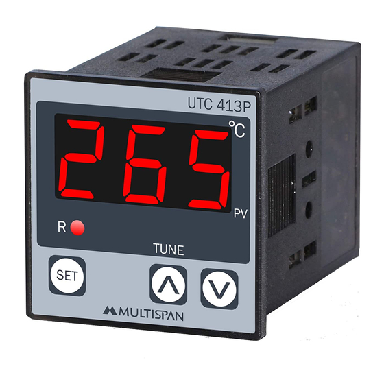
OPERATING MANUAL
PID TEMPERATURE CONTROLLER
UTC - 413P
1 2 3
Technical Specification
Display
3 Digit 7 seg 0.56",red LED Display
Size(HXWXD)
48 X 48 X 70 mm
Panel Cutout(HxW)
45 X 45 mm
Input
J, K, PT-100 (selectable)
Temperature
J: 0 to 600°C / K: 0 to 999°C /
Range
PT-100: -99 to 400ºC
Control Action
PID / ON-OFF (selectable)
Output
1 relay, 1 C/O contact, 230V AC, 5A ; 1 SSR,12V DC Approx, 30mA DC
Power Supply
100 to 270V AC, 50 / 60 Hz, Approx 4VA
Protection Level
IP-65(Front side) AS per IS/IEC 60529:2001
(As per request)
Operating
0°C To 55°C
Temperature
Relative
Up to 95% RH Non Condensing
Humidity
Note:
1) If Sensor Connection is reversed, Display will show "SRE" message.
2) If Sensor is not connected, Display will show Opn message.
3) Every time the instrument is turned ON, Following pattern will be displayed
POWER ON
8
8 8
All digit segment will be turned ON for 3 sec
- J -
Previous or default sensor input will be display for 2 sec
1 2 3
Process Value
Connection Diagram
L
1
N
2
3
NC
C
4
NO
5
UTC-413P
UTC 413P
~
~
6
100
100
270V AC
250V AC
50/60 Hz
50/60 HZ
TC
4VA
4VA
7
-
!
!
RTD
8
www.multispanindia.com
9
R1
10
Made in India
Page - 1
www.multispanindia.com
Safety Precautions
All safety related codifications, symbols and instructions that appear in this operating manual
or on the equipment must be strictly followed to ensure the safety of the operating personnel as
well as the instrument.
If all the equipment is not handled in a manner specified by the manufacturer, it might impair the
protection provided by the equipment .
=> Read complete instructions prior to installation and operation of the unit.
WARNING : Risk of electric shock.
Warning Guidelines
1) To prevent the risk of electric shock power supply to the equipment must be kept OFF while doing the wiring
arrangement. Do not touch the terminals while power is being supplied.
2) To reduce electro magnetic interference, use wire with adequate rating and twists of the same of equal size shall
be made with shortest connection.
2
3) Cable used for connection to power source, must have a cross section of 1mm or greater. These wires
should have insulations capacity made of at least 1.5kV.
4) When extending the thermocouple lead wires, always use thermocouple compensation wires for wiring for the RTD
type, use a wiring material with a small lead resistance (5Ω max per line)and no resistance differentials among
three wires should be present.
5) A better anti-noise effect can be expected by using standard power supply cable for the instrument.
Installation Guidelines
1) This equipment, being built-in-type, normally becomes a part of main control panel and such in case the
terminals do not remain accessible to the end user after installation and internal wiring.
2) Do not allow pieces of metal, wire clippings, or fine metallic fillings from installation to enter the product
or else it may lead to a safety hazard that may in turn endanger life or cause electrical shock to the operator.
3) Circuit breaker or mains switch must be installed between power source and supply terminal to
facilitate power 'ON' or 'OFF' function. However this mains switch or circuit breaker must be
installed at convenient place normally accessible to the operator.
4) Use and store the instrument within the specified ambient temperature and humidity ranges as
mentioned in this manual.
Mechanical Installation
Outline Dimension (mm)
UTC 413P
1 2 3
48
70
3
48
1) Prepare the panel cutout with proper dimensions as show above.
2) Fit the unit into the panel with the help of clamp given.
3) The equipment in its installed state must not come in close proximity to any heating source,
caustic vapors, oils steam, or other unwanted process by products.
4) Use the specified size of crimp terminal (M3.5 screws) to wire the terminal block. Tightening the
screws on the terminal block using the tightening torque of the range of 1.2 N.m.
5) Do not connect anything to unused terminals.
Maintenance
1) The equipment should be cleaned regularly to avoid blockage of ventilating parts.
2) Clean the equipment with a clean soft cloth. Do not use isopropyl alcohol or any other cleaning agent.
3) Fusible resistor must not be replaced by operator.
Product improvement and upgrade is a constant procedure. So for more updated operating information and support,
Please contact our helpline : +91-9978991476/9978991474/9978991482 or Email at service@multispanindia.com
UTC-413P
Panel Cutout
Dimension (mm)
45
45
Page - 2
www.multispanindia.com
Ver: 2102
Advertisement

Related Manuals for MULTISPAN UTC - 413P


Summary of Contents for MULTISPAN UTC - 413P
- Page 1 PID TEMPERATURE CONTROLLER All safety related codifications, symbols and instructions that appear in this operating manual UTC - 413P or on the equipment must be strictly followed to ensure the safety of the operating personnel as well as the instrument.
- Page 2 Key Operation 1 2 3 1 2 3 Press 1) Press Key to go parameter setting. for 3 sec F S T 2) Use key to change value of parameter. Set Point Setting 3) Press Key to save changes in setting. Y E S PID AUTO-TUNING 4) To start or stop Auto-Tuning press...
Need help?
Do you have a question about the UTC - 413P and is the answer not in the manual?
Questions and answers
Properly not sealed