Table of Contents
Advertisement
Quick Links
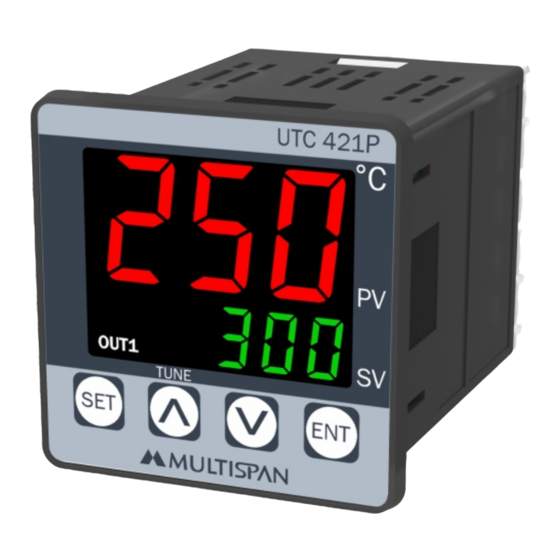
PV = Process Value
SV = Set Value
TECHNICAL SPECIFICATION
INPUT SPECIFICATION:
Input
Input Types
PT-100
PT.1
J,K,PT-100 = 1°C
Resolution
PT.1 = 0.1°C
±1% of FSD ± 1°C
Indication
Accuracy
(FSD:-Full Scale Deflection)
DISPLAY AND KEYS:
Upper: 3 digit, 7 segment, 0.63"
Display
Lower: 3 digit, 7 segment, 0.30"
Keys
SET, INC, DEC, ENT
DIMENSION:
Size
48 (H) x 48 (W) x 70 (D) mm
Panel Cutout
45 (H) x 45 (W) mm
CONTROL METHOD:
1) PID control with Auto-Tuning
2) (TP) Time Proportional
Heating
3) ON-OFF control
Cooling
ON-OFF control
OUTPUT SPECIFICATION:
Relay Output
Relay
1 Nos
Relay Type
1C/O (NO-C-NC)
Rating
10A, 230V AC / 28V DC
SSR Drive Output
12V DC, 30mA DC
Output Signal
(On-Off condition)
TEMPERATURE CONTROLLER
UTC-421P
Display Color:
Upper : RED/WHITE
Lower: Green
Range
J
0 to 600°C,
K
0 to 999°C,
-99 to 400°C,
-19.9 to 99.9°C,
POWER SUPPLY:
Supply
100 to 270V AC, 50-60Hz
Voltage
Power
Consuption
(VA Rating)
ENVIRONMENT CONDITION:
Operating Temp.
0°C to 55°C
UP to 95% RH
Relative Humidity
(non-condensing)
Protection Level
(As per request)
MECHANICAL INSTALLATION
Outline Dimension (mm)
UTC 421P
°
PV
48
OUT1
SV
TUNE
SET
ENT
48
3
TERMINAL CONNECTION
~
100
L
1
270V AC
50/60 HZ
4VA
!
N
2
3
NC
www.multispanindia.com
C
4
R1
NO
5
Sensor Input
6
7
8
3-Wire RTD
6
7
Thermocouple
4VA @ 230V AC MAX
IP-65 (Front side) As per IS/IEC
60529 : 2001
Panel Cutout
Dimension (mm)
45
70
6
T/C
7
-
RTD
8
-
9
SSR
O/P
10
Made in India
6
7
Install jumper
when using
8
2 Wire RTD
2-Wire RTD
45
Page 1
Advertisement
Table of Contents

Subscribe to Our Youtube Channel
Related Manuals for MULTISPAN UTC-421P


Summary of Contents for MULTISPAN UTC-421P
- Page 1 POWER SUPPLY: TEMPERATURE CONTROLLER UTC-421P Supply 100 to 270V AC, 50-60Hz Voltage Power Consuption 4VA @ 230V AC MAX (VA Rating) ENVIRONMENT CONDITION: Operating Temp. 0°C to 55°C UP to 95% RH Relative Humidity (non-condensing) Protection Level IP-65 (Front side) As per IS/IEC...
- Page 2 STATUS LED DESCRIPTION WARNING GUIDELINES WARNING : Risk of electric shock. 1. To prevent the risk of electric shock, power supply to the equipment must be kept OFF while doing the wiring arrangement. Do not touch the terminals while power is being supplied.
- Page 3 ERROR DISPLAY PARAMETER SETTING When an error has occurred the display indicates error codes as given below. Set Point Setting ERROR MEANING Process Value Sensor is not connected or Over range condition or Set Value sensor break Sensor connection is reversed Set Point Press key for 3 sec to...
- Page 4 PARAMETER SETTING ON - OFF control (Cooling) Control Parameter To ENTER CONTROL PARAMETER HYST Password SETTING, ENTER “37” Message IF TP SELECTED IF PID SELECTED RLY-OFF delay delay delay RLY-ON Time Time Time Parameters Parameters Time Proportional Proportional Auto Tuning:- Band Band The Auto-tuning function automatically computes...
Need help?
Do you have a question about the UTC-421P and is the answer not in the manual?
Questions and answers