Advertisement
Quick Links
OPERATING MANUAL
OPERATING MANUAL
PID TEMPERATURE CONTROLLER
TEMPERATURE CONTROLLER
UTC-121, 221 & 421
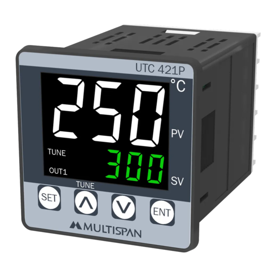
UTC-121P,221P & 421P
1 2 3 4
1 2 3 4
SET
Technical Specification
Technical Specification
Model
UPPER:- 4 Digit 7 seg 0.56",red LED Display
Display
LOWER:- 4 Digit 7 seg 0.4",green LED Display
Size(HXWXD)
96 X 96 X 50 mm
Panel Cutout
92 X 92 mm
Input
Temperature
Range
Control Action
Output
Power Supply
Protection Level
(As per request)
Operating
Temperature
Note:
1) If Sensor Connection is reversed, Display will show "
2) If Sensor is not connected, Display will show
3) Every time the instrument is turned ON, Following pattern will be displayed
POWER ON
8 8 8 8
. . . .
8 8 8 8
. . . .
j
Previous or default sensor input will be displayed for 2 sec
I N P t
0 1 2 3
0 1 2 3
Connection Diagram
Connection Diagram
20
19
18
17
~
100
250V AC
!
50/60 Hz
4VA
N
L
1
2
3
4
UTC-121,221,421
UTC 121
ºC
PV
SV
ENT
UTC 121
UTC 221
72 X 72 X 85 mm
J, K, PT-100 (selectable)
J: 0 to 600°C / K: 0 to 1200°C /
PT-100: -99 to 400ºC /PT.1: -99.0 to 400.0°C
TP / ON-OFF (selectable)
1 relay, 1 C/O contact, 230V AC, 5A ; 1 SSR,12V DC, 30mA DC
100 to 250V AC, 50 / 60 Hz, Approx 4VA
IP-65(Front side) AS per IS/IEC 60529:2001
0°C To 55°C
All digit segment will be turned ON for 3 sec
Process Value
Set Value
16
15
14
13
12
11
-
+
TC
O/P
RTD
S.S.R
RELAY
C
NC
NO
5
6
7
8
9
10
UTC 221
ºC
0 1 2 3
PV
R1
0 1 2 3
SV
SET
ENT
UPPER:- 4 Digit 7 seg 0.39",red LED Display
LOWER:- 4 Digit 7 seg 0.28",green LED Display
68 X 68 mm
Relative
Humidity
SRE
" message.
Open
message.
L
1
~
100
250V AC
TC
50/60 Hz
2
N
4VA
!
RTD
3
NO
4
C
RELAY1
NC
5
6
-
O/P
S.S.R
7
Page - 1
UTC 421
0 1 2 3
0 1 2 3
R
UTC 421
48 X 48 X 95 mm
44 X 44 mm
Up to 95% RH Non Condensing
POWER ON
8 8 88
I N P t
0 1 2 3
8
9
-
L
1
~
~
100
100
10
250V AC
250V AC
50/60 Hz
50/60 HZ
4VA
4VA
N
2
!
!
11
3
NC
12
C
4
13
R1
NO
14
5
www.multispanindia.com
8
8
8
8
j
0 1 2 3
6
TC
7
-
RTD
8
9
10
Advertisement

Related Manuals for MULTISPAN UTC-121P


Summary of Contents for MULTISPAN UTC-121P
- Page 1 OPERATING MANUAL OPERATING MANUAL PID TEMPERATURE CONTROLLER TEMPERATURE CONTROLLER UTC-121, 221 & 421 UTC-121P,221P & 421P UTC 121 ºC 1 2 3 4 UTC 221 ºC 0 1 2 3 1 2 3 4 UTC 421 0 1 2 3...
- Page 2 Key Operation 1) Press key to go parameter setting. 2) Press key to change value or to select option. 3) Press key to save changes in setting. 4) Press key for 3 sec to go to factory setting mode. Set Point Setting 0 0 0 0 PROCESS VALUE 01 0 0 SET VALUE...
- Page 3 1 2 3 4 1 2 3 4 Press for 3 sec F C S T Y E S yes : press key to apply factory set values as shown in table. nO : press key to escape from factory setting. Factory Setting FACTORY SETTING PARAMETER...
- Page 4 Safety Precautions All safety related codifications, symbols and instructions that appear in this operating manual or on the equipment must be strictly followed to ensure the safety of the operating personnel as well as the instrument. If all the equipment is not handled in a manner specified by the manufacturer, it might impair the protection provided by the equipment .
Need help?
Do you have a question about the UTC-121P and is the answer not in the manual?
Questions and answers