
Related Manuals for Advantech ASMB-830 Series


Summary of Contents for Advantech ASMB-830 Series
- Page 1 User Manual ASMB-830 Series Socket SP3 (LGA 4094) AMD EPYC™ 7002/7003 Server Board with 8 REG-DDR4, 5 PCIe 4.0 x16, 2 PCIe 4.0 x8, 2 M.2 NVMe, 9 SATA3, 5 USB 3.2 Gen1, Dual 10GbE, IPMI...
- Page 2 No part of this manual may be reproduced, copied, translated, or transmitted in any form or by any means without the prior written permission of Advantech Co., Ltd. The information provided in this manual is intended to be accurate and reliable.
- Page 3 Advantech has come to be known. Your satisfaction is our primary concern. Here is a guide to Advantech’s cus- tomer services.
- Page 4 Initial Inspection Before installing the motherboard, please make sure that the following materials have been shipped: 1 x ASMB-830 ATX motherboard 1 x ASMB-830 Startup Manual 1 x Serial ATA HDD data cable 1 x I/O port bracket ...
-
Page 5: Table Of Contents
Contents Chapter Overview..........1 Introduction ....................2 Features ....................2 1.2.1 General ..................2 Specifications .................... 3 Table 1.1: Specifications ............. 3 Board Layout, Jumpers and Connectors........... 5 Figure 1.1 Board Layout .............. 5 Figure 1.2 Rear I/O of the Two SKUs .......... 5 Table 1.2: Onboard LAN LED Color Definition ...... - Page 6 2.23 GPIO Connector (GPIO1) ............... 26 Chapter BIOS..........27 Introduction ..................... 28 Figure 3.1 Main Setup Screen........... 28 Entering BIOS Setup................29 3.2.1 Main Menu .................. 29 Figure 3.2 Main Setup Screen........... 29 3.2.2 System Date / System Time ............29 Advanced BIOS Features Setup.............
- Page 7 3.3.12 Network Stack Configuration ............60 Figure 3.40 Network Stack Configuration Screen....... 60 3.3.13 CSM Configuration..............61 Figure 3.41 CSM Configuration Screen........61 Figure 3.42 Boot Option Filter Screen ........62 Figure 3.43 Option ROM Execution - Network Screen ....62 Figure 3.44 Option ROM Execution –...
- Page 8 6.1.1 Introduction ................. 84 6.1.2 Windows Series Driver Setup ............. 84 Appendix A Programming the Watchdog Timer . 85 Watchdog Timer Overview..............86 Programming the Watchdog Timer ............86 Appendix B I/O Pin Assignments ......89 USB 3.2 Gen1 Header (USB3_34) ............90 Table B.1: USB Header (USB3_34) ..........
- Page 9 Table B.26:GPIO Connector (GPIO1)......... 99 ASMB-830 User Manual...
- Page 10 ASMB-830 User Manual...
-
Page 11: Chapter 1 Overview
Chapter Overview... -
Page 12: Introduction
Introduction The ASMB-830 server board is the most advanced AMD EPYC 7002/7003 Proces- sor family board for server-grade IPC applications that require high-performance computing power and multi-expansion slots. This server board supports DDR4 ECC- REG 3200 MHz memory up to 2048 GB. ASMB-830 is equipped with PCIe 4.0 and provides five PCIe x16 slots and two PCIe x8 slots. -
Page 13: Specifications
Specifications Table 1.1: Specifications Processor Single socket LGA4096 SP3 Supports the AMD EPYC 7002/7003 processor family, from 8 to 64 cores (16 to 128 threads) Supports TDP for up to 225 W System Memory DDR4 memory bus ... - Page 14 Table 1.1: Specifications Power Connector 1 x 24-pin SSI EPS 12V power connector (Input 12V, 5V, 3.3V, System Power 5Vsb) 2 x 8-pin SSI EPS 12V power connector for CPU & memory power CPU Power (12V) PCIe slot power 1 x 8-pin 12V power connector for PCIe slot 12V input Expansion Slots 5 x PCIe x16 slots ...
-
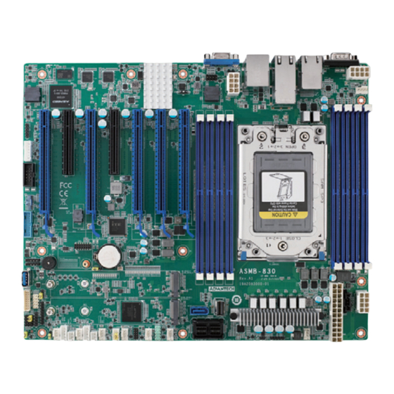
Page 15: Board Layout, Jumpers And Connectors
Board Layout, Jumpers and Connectors Connectors on the ASMB-830 are linked to external devices such as hard disk drives. In addition, ASMB-830 has a number of jumpers that are used to configure the system for specific applications. The tables below list the functions of each jumper and connector. Later sections in this chapter give instructions for setting jumpers. - Page 16 LAN 4 is a shared LAN with BMC. LAN 5 is a dedicated BMC LAN. Table 1.2: Onboard LAN LED Color Definition 10/100/1000 & 10G Mbps LAN Link/Activity LED Scheme LAN1 & LAN2 (1G) LAN3 & LAN4 (10G) Left LED Right LED Link...
- Page 17 Table 1.4: Connectors Label Function ATX12V1 SSI EPS 12V auxiliary power connector for CPU0 and memory ATX12V2 SSI EPS 12V auxiliary power connector ATXPWR1 SSI EPS 24-pin main power connector (for system) For optional battery kit BIOS_SKT1 BIOS SPI ROM BMC_SPI1 BMC SPI ROM COM2...
-
Page 18: Block Diagram
Table 1.5: Onboard LED Description LED Definition Off: On (Green): +5V_LED1 Power on LED Power off System is on On (Green): +5V_S- Off: Standby LED System is on, in sleep mode, B_LED1 No input AC Power or in soft-off mode BMC heartbeat LED BMC_H- Blinking (Green):... -
Page 19: Installation Of Memory Modules
Installation of Memory Modules Memory performance is affected by different DIMM configurations. To reach optimal memory interleaving, be sure to install identical DIMM types with the same size, speed, and number of ranks on those memory slots corresponding to the correct pro- cessor. -
Page 20: Processor Installation
Processor Installation The ASMB-830 is designed for AMD EPYC 7002/7003 Series processors. Unscrew the three screws (shown above in red circles) on the top of the socket retention mechanism (SRM), then rotate the Retention Frame and Rail Frame (with external cap). Remove the external cap by pulling upwards. - Page 21 Rotate and push the rail frame and retention frame until they are in the horizon- tal position. Tighten the three screws (shown above in red circles) by using a T-20 screw- driver. Install the processor heatsink module into the socket retention mechanism (SRM) by using a T-20 screwdriver (follow the heatsink label direction 1-2-3-4).
- Page 22 ASMB-830 User Manual...
-
Page 23: Chapter 2 Connections
Chapter Connections... -
Page 24: Introduction
Introduction You can access most of the connectors from the top of the board as it is being installed in the chassis. If you have a number of cards installed, you may need to par- tially remove a card to make all the connections. USB Ports (USB3_12, USB3_34, USB3_5) The USB ports comply with USB 2.0 and USB 3.2 Gen1. -
Page 25: Vga Connector (Vga1)
VGA Connector (VGA1) The ASMB-830 includes a VGA interface that can drive conventional CRT and LCD displays. VGA1 VGA1 Serial Ports (COM1, COM2) The ASMB-830 offers one serial port on the rear plate and one 2.50 mm on board with 2 x 5-pin pitch. COM1 COM2 COM1... -
Page 26: Ps2 Keyboard And Mouse Connectors (Kbms1)
PS2 Keyboard and Mouse Connectors (KBMS1) The 6-pin KBMS1 connector is for additional keyboard and mouse devices. KBMS1 KBMS1 CPU Fan Connector (CPUFAN0) If a fan is used, this connector supports cooling fans that draw up to 1.5A (18W). CPUFAN0 CPUFAN0 ASMB-830 User Manual... -
Page 27: System Fan Connector (Sysfan0~6)
System Fan Connector (SYSFAN0~6) SYSFAN4 SYSFAN0~6 SYSFAN3 SYSFAN0 SYSFAN5 SYSFAN2 SYSFAN1 SYSFAN6 Front Panel Connector (JFP1+JFP2, JFP3) There are several external switches and LEDs to monitor and control the ASMB-830. JFP1+JFP2 JFP3 JFP1+JFP2 JFP3 ASMB-830 User Manual... -
Page 28: Power Led (Jfp3)
There are several external switches and LEDs to monitor and control the ASMB-830. JFP1+JFP2 JFP3 JFP1+JFP2 JFP3 2.9.1 Power LED (JFP3) JFP3 pin 1 and pin 3 are for the power LED. Refer to Appendix B for detailed infor- mation on the pin assignments. If an ATX power supply is used, the system’s power LED status will be as indicated. -
Page 29: Reset Connector (Jfp1+Jfp2 Pins 9 & 12)
2.9.4 Reset Connector (JFP1+JFP2 Pins 9 & 12) Many computer cases offer the convenience of a reset button. 2.10 Front Panel Connector (JFP1) There are several external switches and LEDs to monitor and control the ASMB-830. JFP1 ASMB-830 User Manual... -
Page 30: Atx Soft Power Switch (Pins 1, 3)
2.10.1 ATX Soft Power Switch (Pins 1, 3) If your computer case is equipped with an ATX power supply, you should connect the power on/off button on your computer case to pins 1 and 3 on JFP1. This connection enables you to turn your computer on and off. 2.10.2 Reset Connector (Pins 2, 4) JFP1 pins 2 &... -
Page 31: Front Panel Lan Indicator Connector (Lanled1)
2.12 Front Panel LAN Indicator Connector (LANLED1) LANLED1 LANLED1 2.13 SATA Connector (SATA_CON1,SATA8) ASMB-830 features eight serial ATA III interfaces (up to 600 MB/s) and eases cabling to hard drives with long and thin cables. SATA8 SATA4~7 SATA0~3 SATA_CON1 SATA8 SATA_CON1 ASMB-830 User Manual... -
Page 32: Connector (M2_22110_1, M2_22110_2)
2.14 M.2 Connector (M2_22110_1, M2_22110_2) The M.2 22110 connector can support both SATA and PCIe SSD devices. M2_22110_1 M2_22110_2 M2_22110_2 M2_22110_1 2.15 PCIe Expansion Slots The ASMB-830 provides seven expansion slots that can support four double-deck cards. The riser card for 1U or 2U chassis can be used in slot 6 only. PCIEX16_SLOT1 PCIEX8_SLOT2 PCIEX16_SLOT3... -
Page 33: Auxiliary Power Connector (Atxpwr1/ Atx12V1/Atx12V2)
2.16 Auxiliary Power Connector (ATXPWR1/ ATX12V1/ATX12V2) ATX12V2 ATX12V1 ATXPWR1 Note! Please use a power supply of SSI type; minimum output should be at least 700W with 5Vsb @ 2.5A. ATXPWR1 & ATX12V1 & ATX12V2 should be all connected to the power supply, otherwise ASMB-830 will not boot up normally. -
Page 34: Lpc Connector (Lpc1)
2.18 LPC Connector (LPC1) ASMB-830 has one LPC connector that can be used to install Advantech's TPM Module (P/N: PCA-TPM-00A1E, PCA-TPM-00B1E) for security management. LPC1 LPC1 2.19 Clear CMOS Connector (JCMOS1) Setting the jumper from pins 1-2 to pins 2-3, then back to pins 1-2 resets the CMOS data. -
Page 35: Pmbus Connector (Pmbus1)
2.20 PMBUS Connector (PMBUS1) PMBUS1 PMBUS1 2.21 Front Panel SMBUS Connector (SMBUS1) SMBUS1 SMBUS1 ASMB-830 User Manual... -
Page 36: Bmc Ic Socket (Bmc_Spi1)
2.22 BMC IC Socket (BMC_SPI1) The IPMI feature can be enabled with BMC_SPI1. The BMC IC socket has already been pre-installed on ASMB-830I and ASMB-830T2. BMC_SPI1 BMC_SPI1 2.23 GPIO Connector (GPIO1) GPIO1 GPIO1 ASMB-830 User Manual... -
Page 37: Chapter 3 Ami Bios
Chapter AMI BIOS... -
Page 38: Introduction
Introduction With the AMI BIOS Setup program, you can modify BIOS settings and control the special features of your computer. The setup program uses a number of menus for making changes and turning special features on or off. This chapter describes the basic navigation of the ASMB-830 setup screens. -
Page 39: Entering Bios Setup
Entering BIOS Setup 3.2.1 Main Menu Press <Del> during bootup to enter the AMI BIOS CMOS setup utility; the Main menu will appear on the screen. Use the arrow keys to select among the items and press <Enter> to accept or enter the submenu. Figure 3.2 Main Setup Screen The Main BIOS setup screen has two main frames. -
Page 40: Advanced Bios Features Setup
Advanced BIOS Features Setup Select the Advanced tab from the ASMB-830 setup screen to enter the Advanced BIOS setup screen. You can select any of the items in the left frame of the screen, such as CPU configuration, to go to the submenu for that item. You can display an Advanced BIOS Setup option by highlighting it using the <Arrow>... -
Page 41: Trusted Computing
3.3.1 Trusted Computing Figure 3.4 Trusted Computing Screen Security Device Support Enables or Disables BIOS support for security devices. Note! Purchase the Advantech LPC TPM module to enable the TPM function. P/N: PCA-TPM-00A1E_B1E. ASMB-830 User Manual... -
Page 42: Psp Firmware Versions
3.3.2 PSP Firmware Versions Figure 3.5 PSP Firmware Versions Screen 3.3.3 AMD CBS Figure 3.6 AMD CBS Screen ASMB-830 User Manual... - Page 43 3.3.3.1 CPU Common Options Figure 3.7 CPU Common Options Screen Core Performance Boost Enable or Disable Core Performance Boost (CPB) options. Global C-state Control Controls I/O-based C-state generation and DF C-states. Local APIC Mode Select local APIC mode: Compatibility, xAPIC or x2APIC.
- Page 44 Performance Figure 3.8 CPU Common Options - Performance Screen OC Mode – Can be used to modify the number of cores/CCD. – Custom Core P-states – CCD/Core/Thread Enablement – SMT Control Can be used to disable symmetric multithreading. To re-enable SMT, a POWER CYCLE is needed after selecting the 'Enable' option.
- Page 45 3.3.3.2 DF Common Options Figure 3.9 DF Common Options Screen Memory Addressing Figure 3.10 DF Common Options - Memory Addressing Screen NUMA nodes per socket – Specifies the number of desired NUMA nodes per socket. ASMB-830 User Manual...
- Page 46 3.3.3.3 NBIO Common Options Figure 3.11 NBIO Common Options Screen IOMMU Enable or Disable IOMMU function. Enable AER Cap Enables Advanced Error Reporting Capability. SMU Common Options ASMB-830 User Manual...
- Page 47 Figure 3.12 SMU Common Options Screen cTDP Control – Auto = Use the fused TDP; Manual = User can set customized TDP. – Package Power Limit Control Auto = Use the fused PPT; Manual = User can set customized PPT. –...
- Page 48 3.3.3.4 FCH Common Options Figure 3.13 FCH Common Options Screen ASMB-830 User Manual...
- Page 49 SATA Configuration Options Figure 3.14 SATA Configuration Options Screen – SATA Enable Disable or enable the OnChip SATA controller. SATA Controller options Figure 3.15 SATA Controller Options Screen ASMB-830 User Manual...
- Page 50 SATA Controller Enable Figure 3.16 SATA Controller Enable Screen Sata0-7 Enable Enable or Disable Sata0~7. Each IOD has 4 SATA Controllers. Sata8 Enable Enable or Disable Sata8. Each IOD has 4 SATA Controllers. ASMB-830 User Manual...
- Page 51 SATA Controller eSATA Figure 3.17 SATA Controller eSATA Screen SATA Port HotPlug Enable or Disable SATA Port0~Port8 HotPlug function. Figure 3.18 SATA Port HotPlug Screen ASMB-830 User Manual...
- Page 52 USB Configuration Options Figure 3.19 USB Configuration Options Screen – XHCI Controller0 enable Enable or disable USB3 controller0. XHCI Controller1 enable – Enable or disable USB3 controller1. – USB ecc SMI Enable Enable or disable USB ECC SMI function. ASMB-830 User Manual...
-
Page 53: It8528 Super Io Configuration
AC Power Loss Options Figure 3.20 AC Power Loss Options Screen AC Loss Control – Select Ac Loss Control Method. 3.3.4 IT8528 Super IO Configuration Figure 3.21 IT8528 Super IO Configuration Screen ASMB-830 User Manual... - Page 54 Serial Port 1 Configuration Figure 3.22 Serial Port 1 Configuration Screen Serial Port – Enable or Disable Serial Port 1. – Change Settings To select an optimal setting for Serial Port 1. ASMB-830 User Manual...
- Page 55 Serial Port 2 Configuration Figure 3.23 Serial Port 2 Configuration Screen Serial Port – Enable or Disable Serial Port 2. – Change Settings To select an optimal setting for Serial Port 2. ASMB-830 User Manual...
-
Page 56: It8528 Hw Monitor
3.3.5 IT8528 HW Monitor Figure 3.24 IT8528 HW Monitor Screen Watchdog Timer Enable or Disable the watchdog timer function. CPU ACPI Shutdown Temperature Enable or Disable the ACPI shutdown temperature threshold. When the system reaches the shutdown temperature, it will be automatically shut down by the ACPI OS to protect the system from overheating damage. - Page 57 Figure 3.25 Fan Configuration Screen ASMB-830 User Manual...
-
Page 58: S5 Rtc Wake Settings
3.3.6 S5 RTC Wake Settings Figure 3.26 S5 RTC Wake Settings Screen Wake system from S5 Enable or disable system wake on alarm event. Select FixedTime, and the sys- tem will wake on the hr:min:sec specified. Select DynamicTime, and the system will wake at the current time + the added minute(s). -
Page 59: Serial Port Console Redirection
3.3.7 Serial Port Console Redirection Figure 3.27 Serial Port Console Redirection Screen COM1 Console Redirection Settings Figure 3.28 COM1 Console Redirection Settings Screen ASMB-830 User Manual... - Page 60 – Terminal Type Select a terminal type to be used for console redirection. Options available: VT100/VT100+/ANSI /VT-UTF8. – Bits Per Second Select the baud rate for console redirection. Options available: 9600/19200/57600/115200 – Data Bits – Parity A parity bit can be sent with the data bits to detect transmission errors. Even: parity bit is 0 if the number of 1's in the data bits is even.
- Page 61 Figure 3.29 Legacy Console Redirection Settings Screen Legacy Console Redirection Settings Select a COM port to display redirection of Legacy OS and Legacy OPROM Messages. ASMB-830 User Manual...
- Page 62 Console Redirection Settings Figure 3.30 Console Redirection Settings Screen Out-of-Band Mgmt Port – To select the com port the user would like to set for console redirection. – Terminal Type EMS Set as "VT100", "VT100+", "VT-UTF8", or "ANSI". "VT-UTF8" is the default setting.
-
Page 63: Cpu Configuration
3.3.8 CPU Configuration Figure 3.31 CPU Configuration Screen SVM Mode Enable/Disable CPU Virtualization. Node 0 Information View memory information related to Node 0 AMD EPYC CPU. Figure 3.32 Node 0 Information Screen ASMB-830 User Manual... -
Page 64: Sio Common Setting
3.3.9 SIO Common Setting Figure 3.33 SIO Common Setting Screen Lock Legacy Resources Enables or disables Lock Legacy Resources. ASMB-830 User Manual... -
Page 65: Pci Subsystem Settings
3.3.10 PCI Subsystem Settings Figure 3.34 PCI Subsystem Settings Screen Above 4G Decoding Enable or Disable 64-bit capable devices to be decoded in the above 4G address space (Only if the system supports 64-bit PCI decoding). Note! Some graphics or GPU cards need to have 4G decoding enabled. SR-IOV Support ... -
Page 66: Usb Configuration
3.3.11 USB Configuration Figure 3.35 USB Configuration Screen Legacy USB Support This is to support a USB device under a legacy OS such as DOS. When "Auto" is selected, the system will automatically detect if a USB device is plugged into the computer and enable USB legacy mode when a USB device is plugged in, or disable USB legacy mode when no USB device is attached. - Page 67 Figure 3.36 USB Transfer Time-Out Screen USB Transfer Time-out The time-out value for Control, Bulk, and Interrupt transfers. Selects the USB transfer time-out value. [1, 5, 10, 20 sec] ASMB-830 User Manual...
- Page 68 Figure 3.37 Device Reset Time-Out Screen Device Reset Time-out USB mass storage device Start Unit command time-out. It selects the USB device reset time-out value [10, 20, 30, 40 sec]. ASMB-830 User Manual...
- Page 69 Figure 3.38 Device Power-Up Delay Screen Device Power-Up Delay This item appears only when Device power-up delay is set to [manual]. Figure 3.39 Mass Storage Devices Screen Mass Storage Devices Default is "Auto" to enumerate mass storage devices according to media format. ASMB-830 User Manual...
-
Page 70: Network Stack Configuration
3.3.12 Network Stack Configuration Figure 3.40 Network Stack Configuration Screen Network Stack Enable or Disable UEFI network stack function. IPv4 PXE support IPv4 HTTP support IPv6 PXE support IPv6 HTTP support PXE boot wait time Media detect count ASMB-830 User Manual... -
Page 71: Csm Configuration
3.3.13 CSM Configuration Enable or disable CSM (Compatibility Support Module) configuration support. When disabled, the system can only support UEFI mode. Figure 3.41 CSM Configuration Screen GateA20 Active This is useful when RT code is executed above 1MB. When it's set as ‘Upon Request’, GA20 can be disabled using BIOS services. - Page 72 Figure 3.42 Boot Option Filter Screen Boot Option Filter Change UEFI/legacy ROM priority for the boot option. Figure 3.43 Option ROM Execution - Network Screen Network Controls the execution of UEFI and legacy PXE OpROM. ASMB-830 User Manual...
- Page 73 Figure 3.44 Option ROM Execution – Storage Screen Storage Control the execution of UEFI and legacy storage OpROM. Video Control the execution of UEFI and legacy Video OpROM. Other PCI devices Determines execution of OpROM policy for devices other than Network, Stor- age, or Video.
-
Page 74: Nvme Configuration
3.3.14 NVMe Configuration NVMe Device Options Settings Figure 3.45 NVMe Configuration Screen 3.3.15 SATA Configuration SATA Device Information Figure 3.46 SATA Configuration Screen ASMB-830 User Manual... -
Page 75: Tls Auth Configuration
3.3.16 TLS Auth Configuration Figure 3.47 TLS Auth Configuration Screen Server CA Configuration Configure Server CA. Enroll or Delete Cert. Figure 3.48 Server CA Configuration Screen ASMB-830 User Manual... -
Page 76: Chipset
Chipset Figure 3.49 Chipset Screen 3.4.1 PCIe Compliance Mode PCIe Link Compliance Mode 3.4.2 PCIe SLOT6 Config Select PCIe SLOT6 Configuration, X16, X8X8, X8X4X4, X4X4X4X4. 3.4.3 Case Open Warning Enable or Disable the Case Open Warning function. ASMB-830 User Manual... -
Page 77: Networking
3.4.4 Networking Figure 3.50 Networking Screen Onboard PCIE LAN(I210) Enable or Disable Intel® I210 Controller support. LAN1(I210) PXE OpROM Enable or Disable the Boot option for the Intel® I210 controller. Onboard PCIE LAN2(I210) Enable or Disable Intel® I210 Controller support. LAN2(I210) PXE OpROM ... -
Page 78: North Bridge
3.4.5 North Bridge Figure 3.51 North Bridge Screen Figure 3.52 Socket 0 Information Screen Socket 0 Information View Information related to Node 0 AMD EPYC CPU. ASMB-830 User Manual... -
Page 79: Security
Security Figure 3.53 Security Screen Note! With AC power & Battery. Short CMOS1 Jumper: Date/Time & Password: Keep Setting: reset to default With AC power and CMOS battery removed. Short CMOS1 Jumper: Date/Time: reset to default Password: keep Setting: reset to default ASMB-830 User Manual... - Page 80 Secure Boot Figure 3.54 Secure Boot Screen Key Management Figure 3.55 Key Management Screen ASMB-830 User Manual...
-
Page 81: Boot
Boot Figure 3.56 Boot Screen Setup Prompt Timeout Number of seconds to wait for setup activation key. Bootup NumLock State Select the keyboard NumLock state as "On" or "Off". Quiet Boot Enable or Disable the quiet boot option. Boot Option Priorities ... -
Page 82: Save & Exit
Save & Exit Figure 3.57 Save & Exit Screen Save Changes and Exit Exit system setup after saving the changes. Discard Changes and Exit Exit system setup without saving any changes. Save Changes and Reset Reset the system after saving changes. Discard Changes and Reset ... -
Page 83: Server Management
Server Management Figure 3.58 Server Management Screen BMC Support Enable or Disable interfaces to communicate with BMC. Wait for BMC If enabled, the motherboard will wait 30 ~ 60 seconds until the BMC module boots up completely. After that, the normal BIOS post screen will be displayed. If disabled, the motherboard will not wait for the BMC module's response. -
Page 84: Bmc Self Test Log
3.8.1 BMC Self Test Log Figure 3.59 BMC Self-Test Log Screen Erase Log Erase log options. When Log is Full Select the action to be taken when the log is full. ASMB-830 User Manual... -
Page 85: Bmc Network Configuration
3.8.2 BMC Network Configuration Figure 3.60 BMC Network Configuration Screen Configuration Address Source Select to configure LAN channel parameters statically or dynamically (by BMC). The Unspecified option will not modify any BMC network parameters during the BIOS phase. ASMB-830 User Manual... -
Page 86: Bmc User Settings
3.8.3 BMC User Settings Figure 3.61 BMC User Settings Screen Figure 3.62 BMC Add User Details Screen ASMB-830 User Manual... -
Page 87: Bmc Sensor Event Configuration
3.8.4 BMC Sensor Event Configuration Enable/Disable System/CPU FAN Sensor Event Figure 3.63 BMC Sensor Event Configuration Screen ASMB-830 User Manual... - Page 88 ASMB-830 User Manual...
-
Page 89: Chapter 4 Chipset Software Installation Utility
Chapter Chipset Software Installation Utility... -
Page 90: Before Beginning
To facilitate the installation of the enhanced display drivers and utility software, read the instructions in this chapter carefully. The drivers for the ASMB-830 are available online for download from the Advantech support website. Before beginning, it is important to note that most display drivers need to have the relevant software application already installed on the system prior to installing the enhanced display drivers. -
Page 91: Chapter 5 Graphics Setup
Chapter Graphics Setup... -
Page 92: Introduction
Introduction Install the ASPEED VGA driver to enable this function, which includes the following features: 32-bit 2D graphics engine on board for normal use. 64 MB RAM for this chip; the highest resolution is 1920x1200. Windows Series Driver Setup When the folder is displayed, navigate to the “Graphic”... -
Page 93: Chapter 6 Lan Configuration
Chapter LAN Configuration... -
Page 94: Lan Configuration
LAN Configuration 6.1.1 Introduction The ASMB-830 has two Gigabit Ethernet LAN connections via dedicated PCI Express x1 lanes: GbE LAN1 - Intel® I210 and GbE LAN2 - Intel® I210; two 10G Base-T LAN connectors LAN3 and LAN4 - Intel® X550. They eliminate the bottle- neck of network data flow and incorporate Gigabit Ethernet at 10 Gbps. -
Page 95: Appendix A Programming The Watchdog Timer
Appendix Programming the Watchdog Timer... -
Page 96: Watchdog Timer Overview
The ASMB-830’s watchdog timer can be used to monitor system software operation and take corrective action if the software fails to function within the programmed period. This section describes the operation of the watchdog timer and how to pro- gram it. Watchdog Timer Overview The watchdog timer is built into the EC controller IT8528E. - Page 97 Wait IBF clear 0x29A, BIT1, = 0 Write 0x29 to 0x29A Stop watchdog Wait IBF clear 0x29A, BIT1, = 0 Go to Step 07 ASMB-830 User Manual...
- Page 98 ASMB-830 User Manual...
-
Page 99: Appendix B I/O Pin Assignments
Appendix I/O Pin Assignments... -
Page 100: Usb 3.2 Gen1 Header (Usb3_34)
USB 3.2 Gen1 Header (USB3_34) Table B.1: USB Header (USB3_34) Signal Signal +5 V STDA_SSRX- STDA_SSRX+ STDA_SSRX-TX- STDA_SSRX+TX+ NC (reserved for OC pin) STDA_SSRX+TX+ STDA_SSRX-TX- STDA_SSRX+ STDA_SSRX- +5 V LAN Ports (LAN1_2, LAN3_4) Table B.2: LAN RJ-45 Port (LAN1_2, LAN3_4) Signal Signal MID0+... -
Page 101: Vga Connector (Vga1)
VGA Connector (VGA1) Table B.3: VGA Connector (VGA1) Signal Signal GREEN BLUE H-SYNC V-SYNC RS-232 Interface (COM1, COM2) 2 4 6 8 1 3 5 7 9 Table B.4: RS-232 Connector (COM1, COM2) Signal ASMB-830 User Manual... -
Page 102: External Keyboard Connector (Kbms1)
External Keyboard Connector (KBMS1) Table B.5: External Keyboard Connector (KBMS1) Signal KB CLK KB DATA MS DATA MS CLK System & CPU Fan Power Connector (SYSFAN0~6, CPUFAN0) Table B.6: CPU FAN Connector (CPUFAN0) CPUFAN0 +12V CPU_FAN0_TACH CPU0_PWM Table B.7: SYS FAN Connector (SYSFAN0~6) SYSFAN0 SYSFAN1 SYSFAN2 SYSFAN3 SYSFAN4 SYSFAN5 SYSFAN6 +12V +12V... -
Page 103: Power Led (Jfp3)
Power LED (JFP3) Table B.8: Power LED Connector (JFP3) Function LED power (3.3 V) Ground External Speaker Connector (JFP1+JFP2) 1 4 7 10 Table B.9: External Speaker Connector (JFP1+JFP2) Function SPK+ SPK- Reset Connector (JFP1+JFP2) 9 12 Table B.10: Reset Connector (JFP1+JFP2) Signal RESET ASMB-830 User Manual... -
Page 104: Hdd Led Connector (Jfp1+Jfp2)
B.10 HDD LED Connector (JFP1+JFP2) Table B.11: HDD LED Connector (JFP1+JFP2) Signal HDD_LED+ HDD_LED- B.11 ATX Soft Power Switch (JFP1+JFP2) Table B.12: ATX Soft Power Switch (JFP1+JFP2) Signal PWR-BTN B.12 ATX Soft Power Switch (JFP1) Table B.13: ATX Soft Power Switch (JFP1) Signal PWR BTN PWR GND... -
Page 105: Reset Connector (Jfp1)
B.13 Reset Connector (JFP1) Table B.14: Reset Connector (JFP1) Signal RST BTN RST GND B.14 Front Panel LAN LED Connector (JFP1) Table B.15: Front Panel LAN LED Connector (JFP1) Signal LAN2_LED+ LAN1_LED+ LAN2_LED- LAN1_LED- ASMB-830 User Manual... -
Page 106: Hdd Led Connector (Jfp1)
B.15 HDD LED Connector (JFP1) Table B.16: SNMP SMBus Connector (JFP2) Signal HDD_LED+ HDD_LED- B.16 Power LED (JFP1) Table B.17: Power LED (JFP1) Signal PWR LED+ PWR LED- ASMB-830 User Manual... -
Page 107: Smbus Connector (Smbus1)
B.17 SMBus Connector (SMBUS1) Table B.18: Front Panel SMBus Connector (SMBUS1) Signal RESUME_SMB_CLK RESUME_SMB_DATA B.18 USB & LAN Ports (LAN5_USB3_12) Table B.19: USB Port (LAN5_USB3_12) Signal VBUS StdA_SSRX- StdA_SSRX+ GND_DRAIN StdA_SSTX- StdA_SSTX- Table B.20: LAN RJ-45 Port (LAN5_USB3_12) Signal Signal MID0+ MID2+ MID0-... -
Page 108: Lpc Connector (Lpc1)
B.19 LPC Connector (LPC1) Table B.21: LPC Connector (LPC1) Signal Signal R_LPCCLK_LPCCN LPC_AD1 LPCRST_LPC_N LPC_AD0 LPC_LFRAME# +3.3V LPC_AD3 LPC_AD2 LPC_SMB_CLK LPC_SERIRQ LPC_SMB_DATA +5V_AUX B.20 Case Open Connector (JCASE1) Table B.22: Case Open Connector (JCASE1) Signal CASEOP B.21 Front Panel LAN LED Connector (LANLED1) Table B.23: LAN LED Connector (LANLED1) Signal Signal... -
Page 109: Clear Cmos Connector (Jcmos1)
B.22 Clear CMOS Connector (JCMOS1) Table B.24: Clear CMOS Connector (JCMOS1) Signal JCMOS1 RTC_RST_PCH B.23 PMBUS Connector (PMBUS1) Table B.25: PMBUS Connector (PMBUS1) Signal PMBUS_SMB_CLK PMBUS_SMB_DATA PMBUS_SW_ALERT# +V3.3_AUX B.24 GPIO Connector (GPIO1) Table B.26: GPIO Connector (GPIO1) Signal Signal EC_GPIO0 EC_GPIO4 EC_GPIO1 EC_GPIO5... - Page 110 No part of this publication may be reproduced in any form or by any means, such as electronically, by photocopying, recording, or otherwise, without prior written permission from the publisher. All brand and product names are trademarks or registered trademarks of their respective companies. © Advantech Co., Ltd. 2023...
Need help?
Do you have a question about the ASMB-830 Series and is the answer not in the manual?
Questions and answers