Table of Contents
Advertisement
Quick Links
Advertisement
Table of Contents

Related Manuals for Advantech USB-4750


Summary of Contents for Advantech USB-4750
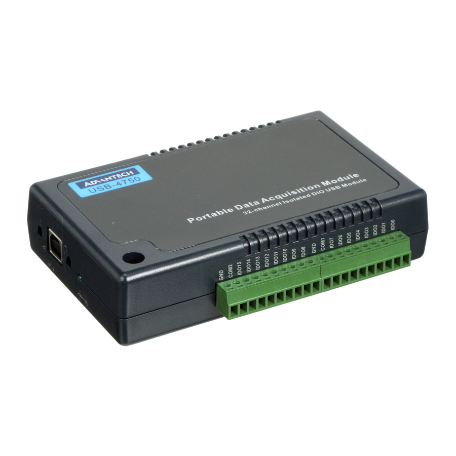
- Page 1 User Manual USB-4750 32-Channel Isolated Digital I/O USB Module...
- Page 2 No part of this manual may be reproduced, copied, translated, or transmitted in any form or by any means without the prior written permission of Advantech Co., Ltd. The information provided in this manual is intended to be accurate and reliable.
- Page 3 This product has passed the CE test for environmental specifications when shielded cables are used for external wiring. We recommend the use of shielded cables. This type of cable is available from Advantech. Please contact your local supplier for ordering information.
- Page 4 USB-4750 User Manual...
-
Page 5: Table Of Contents
Driver Installation ..................5 Figure 2.1 XNavi Installer ............5 2.2.1 Software Development Using DAQNavi SDK ....... 5 Hardware Installation ................6 Hardware Uninstallation ................7 Figure 2.2 Uninstalling USB-4750 ..........7 Chapter Signal Connections ......9 Overview ....................10 I/O Connectors ..................10 3.2.1... - Page 6 USB-4750 User Manual...
- Page 7 Chapter Introduction Sections include: Introduction Features Specifications...
-
Page 8: Chapter 1 Introduction
DAQ devices. All these software packages are available on Advantech website: http://www.advantech.com/. The Advantech Navigator is a utility that allows you to set up, configure and test your device, and later stores your settings in a proprietary database. -
Page 9: Chapter 2 Installation
Chapter Installation Sections include: Unpacking Driver Installation Hardware Installation Hardware Uninstallation... -
Page 10: Unpacking
Unpacking After receiving your USB-4750 package, please inspect its contents first. The pack- age should contain the following items: USB-4750 Module Shielded USB 2.0 Cable (1.72 m) User Manual The USB-4750 Module harbors certain electronic components vulnerable to electro- static discharge (ESD). -
Page 11: Driver Installation
Driver Installation The driver package could be found on Advantech Support Portal (https://www.advan- tech.com/support). Search for USB-4750 on the support portal, then the corre- sponded driver/SDK package could be found. You’ll get the XNavi installer after the download session finishes. -
Page 12: Hardware Installation
Make sure you have installed the software driver before you install the module (please refer to Section 2.2 Driver Installation). After the driver installation is completed, you can now go on to install the USB-4750 module in any USB port that supports the USB 1.1/2.0 standard, on your computer. It is suggested that you refer to the computer’s user manual if you have any doubts. -
Page 13: Hardware Uninstallation
Hardware Uninstallation Though the Advantech USB modules are hot swappable, we still recommend you to follow the hardware un-installation procedure to avoid any unpredictable damage to your device or your system. Close the applications of the USB module. Open the Windows Device Manager and right click on the Advantech USB4750 Device”. - Page 14 USB-4750 User Manual...
-
Page 15: Chapter 3 Signal Connections
Chapter Signal Connections Sections include: Overview Isolated Digital I/O Connections Field Wiring Considerations... -
Page 16: Overview
A good signal connection can avoid unnecessary and costly damage to your PC and other hard- ware devices. I/O Connectors USB-4750 is equipped with plug-in screw-terminal connectors that facilitate connec- tion to the module without terminal boards or cables. 3.2.1 Pin Assignments Figure 3.1 I/O Connector Pin Assignment... -
Page 17: I/O Connector Signal Description
LED indicator status information. Table 3.2: LED Indicator Status Description LED Status Description Device ready for work Device not ready to work Slow Blinking (5 times) Device Initialization Fast Blinking (Depends on data transfer speed) Device working USB-4750 User Manual... -
Page 18: Isolated Digital I/O Connections
Please take care that the current through each GND pin not exceed 200 mA. Figure 3.3 shows how to connect an external output load to the card's isolated out- puts. USB-4750 User Manual... -
Page 19: Field Wiring Considerations
Figure 3.3 Isolated Digital Output Connections Field Wiring Considerations When you use USB-4750 to acquire data from outside, noises in the environ- ment might significantly affect the accuracy of your measurements if due cau- tions are not taken. The following measures will be helpful to reduce possible interference running signal wires between signal sources and the USB-4750. - Page 20 USB-4750 User Manual...
-
Page 21: Appendix A Specifications
Appendix Specifications... -
Page 22: Isolated Digital Input
132 X 80 X 32 mm (5.2” X 3.2” X 1.3”) Power Consumption 5 V @ 350 mA max. Operation 0~60 (32~140) (refer to IEC 68-2-1, 2) Temperature Storage -20~70 (-4~158) Relative Humidity 5%~95% RH non-condensing (refer to IEC 68-2-1, 2) USB-4750 User Manual... - Page 23 USB-4750 User Manual...
- Page 24 No part of this publication may be reproduced in any form or by any means, such as electronically, by photocopying, recording, or otherwise, without prior written permission from the publisher. All brand and product names are trademarks or registered trademarks of their respective companies. © Advantech Co., Ltd. 2022...
Need help?
Do you have a question about the USB-4750 and is the answer not in the manual?
Questions and answers