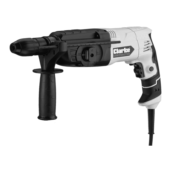
Summary of Contents for Clarke CONTRACTOR CON720RHD
- Page 1 ROTARY HAMMER DRILL MODEL NO: CON720RHD PART NO: 6480215 OPERATION & MAINTENANCE INSTRUCTIONS ORIGINAL INSTRUCTIONS GC 0721- iss 3...
- Page 2 This guarantee does not affect your statutory rights. INVENTORY Unpack your drill and make sure that the following items are present. Should there be any damage caused during transit contact your Clarke dealer immediately. Rotary Hammer Side Handle Assembly (fitted)
-
Page 3: Safety Precautions
SAFETY PRECAUTIONS WARNING: READ ALL INSTRUCTIONS. FAILURE TO FOLLOW ALL INSTRUCTIONS LISTED BELOW MAY RESULT IN ELECTRIC SHOCK, FIRE AND/ OR SERIOUS INJURY. THE TERM “POWER TOOL” IN ALL WARNINGS LISTED BELOW REFERS TO YOUR HAMMER DRILL. WORK AREA 1. Keep the work area clean and well lit. Cluttered and dark areas invite accidents. - Page 4 3. Use safety equipment. Always wear eye protection. Safety equipment such as dust mask, non-skid safety shoes or hearing protection used for appropriate conditions will reduce personal injuries. 4. Avoid accidental starting. Ensure the switch is in the off position before plugging in.
-
Page 5: Hammer Drill Safety Instructions
2. Use the appropriate drill bit for the material being drilled. Different bits are available from your Clarke dealer. 3. Keep the mains cable well away from the drill and ensure an adequate electrical supply is close at hand so that the operation is not restricted by the length of the cable. -
Page 6: Environmental Recycling Policy
15. Use clamps or a vice to hold the work when practical. It is safer than using your hand and it frees both hands to operate the drill. 16. MAKE SURE there are no nails or foreign objects in the part of the workpiece to be drilled. -
Page 7: Electrical Connections
ELECTRICAL CONNECTIONS WARNING: READ THESE ELECTRICAL SAFETY INSTRUCTIONS THOROUGHLY BEFORE CONNECTING THE PRODUCT TO THE MAINS SUPPLY. Before switching the product on, make sure that the voltage of your electricity supply is the same as that indicated on the rating plate. Connecting it to any other power source may cause damage. -
Page 8: Adjusting The Side Handle
SETUP WARNING: TO REDUCE THE RISK OF PERSONAL INJURY, TURN THE UNIT OFF AND DISCONNECT IT FROM THE MAINS SUPPLY BEFORE INSTALLING AND REMOVING ACCESSORIES. ADJUSTING THE SIDE HANDLE 1. Loosen the handle by rotating the shaft of the handle clockwise (when viewed from above) 2. -
Page 9: Inserting And Removing Sds Bits
INSERTING AND REMOVING SDS BITS This machine uses SDS bits and chisels. 1. Wipe clean the bit shank. 2. Pull back the locking sleeve and insert the SDS bit. 3. Release the locking sleeve. 4. Pull on the bit to check if it is properly locked. -
Page 10: Operation
OPERATION PROPER HAND POSITION Always hold the drill securely and use the auxiliary handle as shown. SELECTING THE OPERATING MODE CAUTION: THIS OPERATION SHOULD ONLY BE PERFORMED WHEN THE DRILL IS AT A COMPLETE STOP. 1. Push and hold the red button on the mode selector. -
Page 11: Switching On And Off
SWITCHING ON & OFF 1. Insert the mains plug into a mains power socket. 2. Squeeze the trigger to start the drill. 3. During use, press the trigger lock- on button and the drill will run continuously without you needing to press the trigger. -
Page 12: Drilling Tips
DRILLING TIPS • Always use sharp, good quality drill bits. The performance of your drill is dependant on the quality of the bits used. • After drilling material to the full depth, do not simply pull out the drill but maintain chuck rotation to ease withdrawal. -
Page 13: Before Use
• All bearings etc, in this tool are lubricated with a sufficient amount of high grade lubricant for the tools lifetime under normal operating conditions, therefore no further lubrication is necessary. • Refer to your CLARKE dealer if internal maintenance is required. INDICATORS The Green indicator is a 'Power present' indicator. -
Page 14: Specifications
Dimensions (L x W x H) 400 x 250 x 90 mm Weight 3.5 Kg REPLACEMENT PARTS The following parts are replaceable by the end user, refer to the Clarke servicing department for any other repairs or damage. ESCRIPTION UMBER Dust Shield Cap... -
Page 15: Declarations Of Conformity
DECLARATIONS OF CONFORMITY Parts & Service: 020 8988 7400 / E-mail: Parts@clarkeinternational.com or Service@clarkeinternational.com...


Need help?
Do you have a question about the CONTRACTOR CON720RHD and is the answer not in the manual?
Questions and answers