
Related Manuals for Clarke Metalworker CMD10


Summary of Contents for Clarke Metalworker CMD10
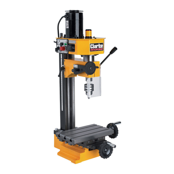
- Page 1 MICRO MILLING/DRILLING MACHINE MICRO MILLING/DRILLING MACHINE MODEL No. CMD10 MODEL No. Part No. 7610850 Part No. 6460200 OPERATING & MAINTENANCE INSTRUCTIONS 0403...
- Page 2 NOTES -18-...
-
Page 3: Guarantee
Service@clarkeinternational.com Please note that the details and specifications contained herein are correct at the time of going to print. However CLARKE International reserve the right to change specifications at any time without prior notice. Always consult the machines data plate... -
Page 4: Table Of Contents
Table Effective Size: ............240mm x 145mm Table Cross Travel: ................90mm Table Longitudal Travel: ..............180mm IMPORTANT: he use of parts other than CLARKE replacement parts may result in safety hazards, decreased tool performance and may invalidate your warranty. -16-... -
Page 5: Safety Precautions
Safety Precautions Item Part No Description SG10051 Handle SG10052 Pin 3 x 12 WARNING: SG10053 Joint Shaft As with all machinery, there are certain hazards involved with their operation SG10054 Screw M5 x 18 and use. Exercising respect and caution will considerably lessen the risk of SG10055 Joint Screw personal injury. - Page 6 SG10027 Compression Ring SG10028 Round Nut Stop Gasket Replacement cutters are available from your CLARKE dealer. SG10029 Round Nut M24 x 1.5 Ensure the cutter is fully tightened before use. SG10030 Spindle Gear Switch the machine OFF immediately the task is completed.
-
Page 7: Electrical Connections
If a cable extension is needed, it is essential to comply with the following data. Voltage Extension length Cable section A wide range of accessories is available from your nearest CLARKE dealer, for further 230v Up to 20m 2.5mm information, contact your nearest dealer, or telephone CLARKE International Sales... -
Page 8: Wiring Diagram
Electrical Circuit Diagram 230v 50Hz Maintenance (Figures in brackets refer to parts diag page 11) The amount of maintenance depends on the amount of use the machine gets, however it is important to carry out routine maintenance to prevent premature wear and shortening the life of the machine. -
Page 9: Unpacking
Operating Instructions Unpacking Unpack machine and accessories, lay out neatly on work surface or similar. these instructions are not definitive, they are to be used for guide purposes NOTE: only and are not intended to teach you all there is to know about milling and drilling. Open case top, remove loose items from top of packing. -
Page 10: Installation & Assembly
(see Fig. 3), whilst holding spindle with tommy bar, loosen Installation and Assembly (Figures in brackets refer to parts diag page 13) the spindle draw bar using 8mm spanner (see Fig. 4). Wall Remove tommy bar, and store safely. Unscrew the draw bar approx three full turns, whilst supporting the drill chuck IMPORTANT: Careful...
Need help?
Do you have a question about the Metalworker CMD10 and is the answer not in the manual?
Questions and answers
What is the overall hight of the machine
The overall height of the Clarke Metalworker CMD10 machine is 36 inches.
This answer is automatically generated