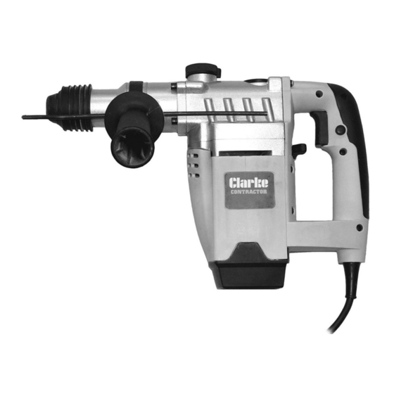
Summary of Contents for Clarke CONTRACTOR CRD1250
- Page 1 ROTARY HAMMER DRILL MODEL NO: CRD1250 PART NO: 6482015 OPERATION & MAINTENANCE INSTRUCTIONS GC0913...
-
Page 2: Safety Precautions
INTRODUCTION Thank you for purchasing this CLARKE Hammer Drill. The CRD1250 is designed for general drilling/masonry drilling/chiselling/drill & hammer use in light industrial applications. Before attempting to use this product, please read this manual thoroughly and follow the instructions carefully. In doing so you will ensure the safety of yourself and that of others around you, and you can look forward to your purchase giving you long and satisfactory service. -
Page 3: Electrical Safety
ELECTRICAL SAFETY 1. Avoid body contact with earthed or grounded surfaces such as pipes, radiators, ranges or refrigerators. There is an increased risk of electric shock if your body is earthed or grounded. 2. Do not expose power tools to rain or wet conditions. Water entering a power tool will increase the risk of electric shock. -
Page 4: Safety Symbols
5. Maintain power tools. Check for misalignment or binding of moving parts, breakage of parts and any other condition that may affect the power tools operation. If damaged, have the power tool repaired before use. Many accidents are caused by poorly maintained power tools. 6. -
Page 5: Electrical Connections
ELECTRICAL CONNECTIONS WARNING! Read these electrical safety instructions thoroughly before connecting the product to the mains supply. This product battery charger is provided with a standard 13 amp, 230 volt (50Hz), BS 1363 plug, for connection to a standard, domestic electrical supply. Should the plug need changing at any time, ensure that a plug of identical specification is used. - Page 6 OVERVIEW NO DESCRIPTION NO DESCRIPTION Dust Guard Hammer Control Fastening Sleeve Drill Control Switch Trigger Lock Pin Handle Attachment 10 Off-Lock Knob Rear Cover 11 Greasing Point Cover Depth Stop Parts & Service: 020 8988 7400 / E-mail: Parts@clarkeinternational.com or Service@clarkeinternational.com...
-
Page 7: Carton Contents
CARTON CONTENTS The following items should be supplied in the carton. If any parts are missing or damaged, please see your Clarke dealer. Moulding plastic carrying case Black moulded bit case Rotary Hammer Drill 8mm SDS plus masonry drill bit... -
Page 8: Fitting And Changing Tools
2. Check the mains voltage before plugging in and switching on. FITTING AND CHANGING TOOLS 1. Clean tools, and apply a thin film of grease before fitting. 2. Pull back the fastening sleeve and hold, push and rotate the dust free tool Into the tool holder as far as it will go, release the fastening sleeve, the tool will then be locked in automatically. -
Page 9: Drilling Tips
4. Set the required mode, (see Drill Mode Selection below). • When drilling vertically overhead, fit the rubber dust collector shown onto the drill. 5. Position the tool against the surface to be drilled, depress the OFF lock knob (10) and then squeeze the trigger switch (3). -
Page 10: Maintenance And Servicing
2. After drilling material to the full depth, do not simply pull out the drill but maintain chuck rotation to ease withdrawal. 3. Reduce the pressure on the drill bit when it is about to break through. This will prevent the drill from jamming. 4. -
Page 11: Specifications
6. At the end of work, to prevent dust deposits you should use a compressed air (max.3 bar) to clean out the ventilation holes. 7. Remove and inspect the carbon brushes regularly, it is very important to refit the motor brushes exactly as they are removed, DO NOT turn them around or swap their positions (dirty or worn carbon brushes result in excessive sparking and speed faults). -
Page 12: Parts Diagram
PARTS DIAGRAM Parts & Service: 020 8988 7400 / E-mail: Parts@clarkeinternational.com or Service@clarkeinternational.com... -
Page 13: Parts List
PARTS LIST DESCRIPTION DESCRIPTION O-Ring O-Ring (A) Cylinder O-Ring (B) Second Striker Spring Spring Large Bevel Gear Gear Case Circlip Bearing 6001 Rotor O-Ring Wind Guide Piston Pin Spring Washer 10 Piston Hex Screw 11 Connecting Rod Brush Holder 12 O-ring Insert Sheet 13 Circlip O-Ring... - Page 14 DESCRIPTION DESCRIPTION 61 Second Gear Bearing Cover 62 Wheel Core Circlip 63 Circlip First Gear 64 Bearing 6002-Z Needle Bearing 65 Small Bevel Gear Screw 66 Spring Right Handle 67 Fixed Plate Cable Sleeve 68 Screw Cable & Plug 69 Spring Washer Cable Anchor 70 Plain Washer Self-tapping Screw...
-
Page 15: Declaration Of Conformity
DECLARATION OF CONFORMITY Parts & Service: 020 8988 7400 / E-mail: Parts@clarkeinternational.com or Service@clarkeinternational.com... - Page 16 Parts & Service: 020 8988 7400 / E-mail: Parts@clarkeinternational.com or Service@clarkeinternational.com...


Need help?
Do you have a question about the CONTRACTOR CRD1250 and is the answer not in the manual?
Questions and answers