
Related Manuals for Kyoto Kagaku M74


Summary of Contents for Kyoto Kagaku M74
- Page 1 INTRAMUSCULAR INJECTION SIMULATOR 2-WAYS MODEL User's Instruction Movie Site KYOTO KAGAKU CO., LTD. English Site https://youtu.be/6XEbQBKK2UE...
- Page 2 DOs and DONʼTs DONʼTs ●Operate the system under the designated ●Do not disassemble or open electric or circumstances precision components Power input: AC100V~230V plus or minus 10%, 50Hz/60Hz Do not open up or disassemble the housing for electric parts Temperature range: between 0 degrees C and 40 degrees C or precision components.
- Page 3 P lease note, do not allow the electrical mechanism to be in touch with water. When irregularity found during use, please contact the original dealer, or KK Kyoto Kagaku (details of contact are listed at the end of this Instruction ) .
-
Page 4: Specification
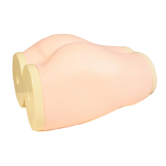
M odel:Shape o f adult woman (in real size) M aterial:Soft special resin, hard resin ( 3-layer con s truction) Weight:A b out 3.2kg (the mode l ) Power: 9V B atte r y M ain M odel · · · · · · · · · · · · · · · · · · · · · · · · · · · · · · · · · · · · · · · · · · · · · · · · · · · · · · · · · · · · · · · · · · · · · · · · · · · · · · · · · · · · · · · · · · · · · · · · · · · · · · · · · · · · · · · · · · · · · · · · · · · · · · · · · · · · · · · 1 D i s p l ay b o x o f acc u racy ·····... -
Page 5: Use Method
Power can be supplied by 9V battery. When changing dry battery-open the cover at the rear of Accuracy Display Box, and install dry battery into the internal socket. Insert the wire plug of Accuracy Display Box into Connector A of Model Main Body (Hold the rubber part of the plug, press gently to the connector and turn, it will fit into the groove and slip in). - Page 7 2. Remove all the internal connector. -+ Remove this portion along with pressing. 3. Do not pull the skin forcefully, but remove slowly from the bottom. Removing only the skin -+ @ Covering with skin Replacing sensor of injection location ( dismantle) * 4 section 3 section, Hochstetter's site sensor Remove the fastener pull off the tube then the connector in sequence.
- Page 8 Covering with skin * 4 section 3 section, Hochstetter's site sensor Clark point sensor Replacing the injection location sensor (Installation) Insert connector (1) and connector (2) into the hold under but- terfly bone, and the location sensor shall be join with the fas tener at the bottom seat.
- Page 9 After use, please keep in the purpose box and in cool and dry location. Change of parts and components Precautions in uses Information or irregularity of the product, please check with your dealer or the following units. D KYOTO KAGAKU CO •• LTD e-mail: rw-kyoto@kyotokagaku.co.jp URL: http://www.kyotokagaku.com Worldwide Inquiries &...
Need help?
Do you have a question about the M74 and is the answer not in the manual?
Questions and answers