
Subscribe to Our Youtube Channel
Related Manuals for Lanner NCA-4220


Summary of Contents for Lanner NCA-4220
- Page 1 NCA-4220 User Manual Network Appliance Platform Hardware Platforms for Network Computing NCA-4220 User Manual Version: 1.2 Date of Release:2024-04-09...
- Page 2 - assumed to be qualified in the servicing of computer equipment, such as professional system integrators, or service personnel and technicians. The latest version of this document can be found on Lanner’s official website, available either through the product page or through the Lanner Download Center page with a login account and password.
- Page 3 NCA-4220 User Manual Contact Information Taiwan Corporate Headquarters China Lanner Electronics Inc. Beijing L&S Lancom Platform Tech. Co., Ltd. 7F, No.173, Sec.2, Datong Rd. Guodong LOFT 9 Layer No. 9 Huinan Road, Xizhi District, New Taipei City 22184, Huilongguan Town, Changping District, Beijing...
- Page 4 NCA-4220 User Manual Copyright and Trademarks This document is copyrighted © 2024. All rights are reserved. The original manufacturer reserves the right to make improvements to the products described in this manual at any time without notice. No part of this manual may be reproduced, copied, translated or transmitted in any form or by any means without the prior written permission of the original manufacturer.
- Page 5 NCA-4220 User Manual Safety Guidelines Follow these guidelines to ensure general safety: Keep the chassis area clear and dust-free during and after installation. Do not wear loose clothing or jewelry that could get caught in the chassis. Fasten your tie or scarf and roll up your sleeves.
- Page 6 The installation of this product must be performed by trained specialists; otherwise, a non-specialist might create the risk of the system’s falling to the ground or other damages. Lanner Electronics Inc. shall not be held liable for any losses resulting from insufficient strength for supporting the system or use of inappropriate installation components.
- Page 7 NCA-4220 User Manual Electrical Safety Instructions Before turning on the device, ground the grounding cable of the equipment. Proper grounding (grounding) is very important to protect the equipment against the harmful effects of external noise and to reduce the risk of electrocution in the event of a lightning strike.
-
Page 8: Table Of Contents
NCA-4220 User Manual Table of Contents Chapter 1: Product Overview ............10 Package Content ......................... 10 Ordering Information ......................... 11 Optional Accessories ........................11 System Specifications ......................... 12 Front Panel ..........................13 Rear Panel ........................... 13 Motherboard Information ......................14 Chapter 2: Hardware Setup ............. - Page 9 NCA-4220 User Manual Save and Exit Menu ........................79 Appendix A: LED Indicator Explanations ........81 Appendix B: Terms and Conditions ..........82 Warranty Policy .......................... 82...
-
Page 10: Chapter 1: Product Overview
CHAPTER 1: PRODUCT OVERVIEW The NCA-4220 series unit is a mid range 1U rackmount network security system utilizing the cutting edge capabilities of the Intel Coffee Lake refresh CPU. The system supports up to 8 x GbE RJ45 with Gen3 bypass and 1x front NIC modules. -
Page 11: Ordering Information
HDD/SSD (15mm height) NIC Module Note: It is strongly recommended to use Lanner Slim type NIC modules on this system; please consult Lanner for product compatibility if you consider adopting modules manufactured by other vendors. RJ45 cable L=180cm, Cat.5e UTP Cable Grey USB3.0 cable... -
Page 12: System Specifications
NCA-4220 User Manual System Specifications Form Factor 1U 19“ Rackmount Intel® Xeon® E or Core™ i7/i5/i3 or Pentium® or Processor Options Celeron® (Codename Coffeelake) Platform CPU Socket 1x LGA1151 socket Chipset Intel® C246/Q370/H310 BIOS AMI SPI Flash BIOS Technology DDR4 up to 2666GHz; ECC /U DIMM; 8/16GB (by SKU) System Memory Max. -
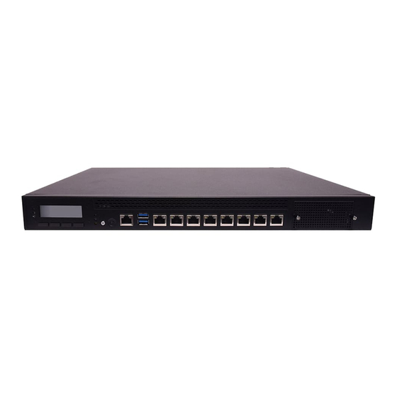
Page 13: Front Panel
NCA-4220 User Manual Front Panel NIC Slot Description System LED Indicators Power System Status Control Panel 1x LCM + 4x control keys Reset Button Default SW Reset Console Port 1x RJ45 Console Port USB Ports 2x USB 3.0 Port PXE Ports... -
Page 14: Motherboard Information
NCA-4220 User Manual Motherboard Information Block Diagram The block diagram indicates how data flows among components on the motherboard. Please refer to the following figure for your motherboard’s layout design. - Page 15 NCA-4220 User Manual Motherboard Layout The motherboard layout shows the connectors and jumpers on the board. Refer to the following picture as a reference for the pin assignments and the internal connectors. USB1 PCIE SLOT1 PCIE1 MPCIE1 ATX1 JLPC1 M2_1...
- Page 16 NCA-4220 User Manual Internal Jumpers The pin headers on the motherboard are often associated with essential functions. With the shunt (Jumper) pushed down on the designated pins (the pin numbers are printed on the circuit board, surrounding the pin header), particular features can be enabled or disabled. While changing the jumpers, make sure your system is turned off.
- Page 17 NCA-4220 User Manual Internal Connectors USB 3.0/2.0 Interfaces USB1:USB Connector 2x10 Pins 2.0mm USB2:USB3.0 Double-Stacked Type-A Connectors PIN NO. DESCRIPTION PIN NO. DESCRIPTION V5USB USB3_RX3_N USB3_RX3_P USB3_TX4+1 USB3_TX3_N USB3_TX4-1 USB3_TX3_P USB3_RX4+1 USB3_RX4-1 V5USB Serial Console Interface COM1: Serial Console Pin Definitions...
- Page 18 NCA-4220 User Manual SATA Interface SATA1/SATA2: 7-pin SATA signal connector for SATA storage devices PAD1 Pin number Pin signal PAD1 Ground Ground PAD2 PAD2 Ground FAN Connectors FAN1~FAN3 cooling fan pin definition Description P12V FANIN FANOUT Digital I/O GP1: DIO Connector...
- Page 19 NCA-4220 User Manual ATX Power ATX2: 4-pin ATX power supply connector Pin signal Ground VCC12 (12V) Ground VCC12 (12V) ATX1: 24-pin ATX power supply connector Description Description +3.3V +3.3V +3.3V -12V Ground Ground PSON- Ground Ground Ground Ground Ground Power Good...
-
Page 20: Chapter 2: Hardware Setup
Installing the CPU 1. Power off NCA-4220 completely. 2. Remove the two screws at the rear, as circled in the figures below. 3. Slide and pull the top compartment as the arrow of direction below. Lift the top compartment. - Page 21 NCA-4220 User Manual 5. When you extract the processor from its package, carefully hold it by its edges and avoid touching its golden contacts side. Make sure the golden triangular mark is aligned with the white one marked on the motherboard and then insert it into the socket, as indicated in the picture.
-
Page 22: Installing The System Memory
NCA-4220 User Manual Installing the System Memory The motherboard supports 2 memory slots for DDR4 UDIMM with speeds of up to 2666MHz. The CPU requires at least 2 memory modules to boot and run from. Supported System Memory Summary Total Slots... -
Page 23: Installing The Tpm Module
NCA-4220 User Manual Installing the TPM Module This system supports the TPM module card (IAC-TPM01C) through the TPM slot. 1. Locate the TPM slot. 2. Insert the TPM module into the 12-pin slot. Make sure it is properly seated. -
Page 24: Installing The M.2 Storage Card
NCA-4220 User Manual Installing the M.2 Storage Card This system supports the M.2 storage module (2242 B+M Key) through the M2_1 slot. 1. Locate the M2_1 slot. M2_1 2. Insert the M.2 module into the slot at 15° angle, align the notch on the module with the corresponding socket key in the slot, and then secure it with a screw. -
Page 25: Installing The Nic Modules
NCA-4220 User Manual Installing the NIC Modules This system can accommodate one NIC slim type modules at the front and another one at rear FH/HL PCIe expansion slot. Based on your application requirements, employ a combination of Riser Cards to fulfill your needs: 1. - Page 26 NCA-4220 User Manual Model Ports Connector Speed Chipset PCIE Interface NCS2-IGM806A 1Gb RJ-45 Intel i350AM-4 2* PCIEx4 NCS2-IGM808A 1Gb RJ-45 PEX8618, Intel I210AT 1* PCIEx8 NCS2-ISM802A 1Gb SFP Intel i350AM-4 2* PCIEx4 NCS2-ISM803A 1Gb SFP Intel i350AM-4,PEX8616 1* PCIEx8 NCS2-IMM802A...
-
Page 27: Installing The Hard Disks
NCA-4220 User Manual Installing the Hard Disks The system can accommodate two 2.5” SSD/HDD (15mm height) at its front disk bay. With the optional SSD swappable cage, you can add another two SSD disks for system storage. After you install the hard drives, make sure the SATA data cables and SATA power cables are connected to the designated connectors on the motherboard, as indicated in the picture below. - Page 28 NCA-4220 User Manual 3. Take the tray out and prepare to install a SATA 2.5” disk drive. 4. Place the disk drive as shown in the image below. Apply 2 screws for each side of the disk drive. 5. Place the tray with HDD/SSD installed back to its original spot inside the system. Remember to aim the two latching holes.
-
Page 29: Installing The Vga Module
Installing the VGA Module The NCA-4220 can support VGA port by ordering the optional VGA kit, which includes a VGA module card IAC-MVGA03A and a VGA cable. Before installing the card to the mini PCI-E slot on the motherboard, please connect the cable on the VGA card as below: 1. -
Page 30: Mounting The System
NCA-4220 User Manual Mounting the System There are various methods to mount this system based on your application and the environment. This system came with two types of mounting kits for a typical rack or enclosure mounting installation or installing this... -
Page 31: Chapter 3: Software Setup
NCA-4220 User Manual CHAPTER 3: SOFTWARE SETUP BIOS Setup The system has AMI BIOS built-in, with a SETUP utility that allows users to configure required settings or to activate certain system features. Pressing the <Tab> or <DEL> key immediately allows you to enter the Setup Utility. -
Page 32: Main Page
NCA-4220 User Manual Main Page Setup main page contains BIOS information and project version information. Feature Description BIOS Vendor: American Megatrends Core Version: AMI Kernel version, CRB code base, X64 Compliancy: UEFI version, PI version BIOS Information Project Version: BIOS release version... -
Page 33: Advanced Page
NCA-4220 User Manual Advanced Page Select the Advanced menu item from the BIOS setup screen to enter the “Advanced” setup screen. Users can select any of the items in the left frame of the screen. - Page 34 NCA-4220 User Manual CPU Configuration...
- Page 35 NCA-4220 User Manual Feature Options Description Disabled Enable/Disable moving of DRAM contents to PRM memory C6DRAM Enabled when CPU is in C6 state Software Guard Disabled Enable/Disable Software Guard Extensions (SGX) Extensions (SGX) Enabled CPU Flex Ratio Disabled Enable/Disable CPU Flex Ratio Programming...
- Page 36 NCA-4220 User Manual Power & Performance Feature Options Description Max Battery Boot performance Max Non-Turbo Select the performance state that the BIOS will set mode Performance starting from reset vector. Turbo Performance" Intel(R) Disabled Allows more than two frequency ranges to be...
- Page 37 NCA-4220 User Manual PCH-FW Configuration Feature Options Description Disabled When Disabled ME will be put into ME Temporarily ME State Enabled Disabled Mode.
- Page 38 NCA-4220 User Manual PCH-FW Configuration Feature Options Description Me FW Image Disabled Enable/Disable Me FW Image Re-Flash function. Re-Flash Enabled...
- Page 39 NCA-4220 User Manual Trusted Computing Feature Options Description Enables or disables BIOS support for security device. By Security Device Enabled disabling this function, OS will not show Security Device. TCG Support Disabled EFI protocol and INT1A interface will not be available.
- Page 40 NCA-4220 User Manual Trusted Computing (TPM1.2) Feature Options Description Enables or disables BIOS support for security device. By Security Device Enabled disabling this function, OS will not show Security Device. TCG Support Disabled EFI protocol and INT1A interface will not be available.
- Page 41 NCA-4220 User Manual Trusted Computing (TPM2.0)
- Page 42 NCA-4220 User Manual Feature Options Description Enables or disables BIOS support for security device. By Security Device Enabled disabling this function, OS will not show Security Device. TCG EFI Support Disabled protocol and INT1A interface will not be available. Enabled SHA-1 PCR Bank Enables or disables SHA-1 PCR Bank.
- Page 43 NCA-4220 User Manual Super IO Configuration...
- Page 44 NCA-4220 User Manual Serial port 1 Configuration Feature Options Description Enabled Serial Port Enables or disables Serial Port 1. Disabled Device Settings IO=3F8h; IRQ = 4...
- Page 45 NCA-4220 User Manual Serial port 2 Configuration Feature Options Description Enabled Serial Port Enables or disables Serial Port 2. Disabled Device Settings IO=2F8h; IRQ = 3...
- Page 46 NCA-4220 User Manual H/W Monitor Feature Options Description Smart Fan Control None Smart Fan Parameters...
- Page 47 NCA-4220 User Manual Smart Fan Control Feature Options Description Manual Mode Smart Fan Mode Smart Fan Mode select Smart Fan Mode Target Input Target Temperature (Range:0 - 127) Temperature T1 Target Input Target Temperature (Range:0 - 127) Temperature T2 Target...
- Page 48 NCA-4220 User Manual Status LED Configuration Feature Options Description Status LED Green Configures Status LED color...
- Page 49 NCA-4220 User Manual Digital I/O Configuration Feature Options Description Output Low Digital I/O Output 1 Configure Digital I/O Pin1 Output High Output Low Digital I/O Output 3 Configure Digital I/O Pin3 Output High Output Low Digital I/O Output 5 Configure Digital I/O Pin5...
- Page 50 NCA-4220 User Manual Case Open Configuration Feature Options Description Enabled Case Open Enables or disables Case Open function Disabled...
- Page 51 NCA-4220 User Manual Watch Dog Timer Configuration Feature Options Description Enabled Watch Dog Timer Enables or disables Watch Dog Timer function Disabled...
- Page 52 NCA-4220 User Manual Serial Port Console Redirection Feature Options Description COM0 Enabled Console Enables or disables Console Redirection Disabled Redirection...
- Page 53 NCA-4220 User Manual Console Redirection Settings Feature Options Description VT100: ASCII char set VT100 VT100+:Extends VT100 to support color, function keys, etc. VT100+ Terminal Type VT-UTF8:Uses UTF8 encoding to map Unicode chars onto 1 or VT-UTF8 more bytes ANSI ANSI: Extended ASCII char set...
- Page 54 NCA-4220 User Manual VT-UTF8 Combo Key Disabled Enables VT-UTF8 Combination Key Support for ANSI/VT100 Support Enabled terminals Disabled With this mode enabled, only text will be sent. This is to capture Recorder Mode Enabled Terminal data. Disabled Resolution 100x31 Enables or disables extended terminal resolution...
- Page 55 NCA-4220 User Manual Console Redirection Settings Feature Options Description Redirection COM COM0 Select a COM port to display redirection of Legacy OS and Port Legacy OPROM Messages. 80x24 On Legacy OS, the Number of Rows and Columns supported Resolution 80x25 redirection.
- Page 56 NCA-4220 User Manual Intel TXT Information...
- Page 57 NCA-4220 User Manual PCI Subsystem Settings Feature Options Description BME DMA Disabled Re-enable Bus Master Attribute disabled during PCI Mitigation Enabled enumeration for PCI Bridges after SMM Locked Globally Enables or Disables Hot-Plug support for the entire Disabled System. If System has Hot-Plug capable Slots and this option...
- Page 58 NCA-4220 User Manual USB Configuration Feature Options Description Enables Legacy USB support. Enabled Auto option disables legacy support if no USB devices Legacy USB Support Disabled are connected; Auto Disabled option will keep USB devices available only for EFI applications.
- Page 59 NCA-4220 User Manual This is a workaround for OSes without XHCI hand-off Enabled XHCI Hand-off support. The XHCI ownership change should be claimed Disabled by XHCI driver. USB Mass Storage Enabled Enables or disables USB Mass Storage Driver Support. Driver Support...
- Page 60 NCA-4220 User Manual Network Stack Configuration Feature Options Description Disabled Network Stack Enables or disables UEFI Network Stack Enabled...
- Page 61 NCA-4220 User Manual CSM Configuration Feature Options Description Disabled CSM Support Enables or disables CSM Support Enabled Do Not Launch Network UEFI Controls the execution of UEFI and Legacy PXE OpROM Legacy Do Not Launch Controls the execution of UEFI and Legacy Storage...
- Page 62 NCA-4220 User Manual NVMe Configuration...
- Page 63 NCA-4220 User Manual Control Legacy PXE Boot Feature Options Description Disabled Control Legacy MGMT Lan1 Control Legacy PXE Boot from which Lan PXE Boot from MGMT Lan2...
-
Page 64: Chipset
NCA-4220 User Manual Chipset Select the Chipset menu item from the BIOS setup screen to enter the Platform Setup screen. Users can select any of the items in the left frame of the screen. - Page 65 NCA-4220 User Manual System Agent (SA) Configuration Feature Options Description Disabled VT-d VT-d capability Enabled Enable/Disable above 4GB MemoryMappedIO BIOS Above 4GB MMIO Disabled assignment This is enabled automatically when Aperture BIOS assignment Enabled Size is set to 2048MB. Disabled...
- Page 66 NCA-4220 User Manual Memory Configuration Feature Options Description Maximum Memory Auto Maximum Memory Frequency Selections in Mhz. Valid Frequency 1067~3200 values should match the refclk, i.e. divide by 133 or 100 Maximum Value of TOLUD. Dynamic assignment would Dynamic Max TOLUD adjust TOLUD automatically based on largest MMIO length 1 GB~3.5GB...
- Page 67 NCA-4220 User Manual PEG Port Configuration...
- Page 68 NCA-4220 User Manual Feature Options Description Disabled Enable Root Port Enabled Enable or Disable the Root Port Auto Auto Gen1 Max Link Speed Configure PEG 0:1:0 Max Speed Gen2 Gen3 Sets the upper limit on power supplied by slot. Power limit...
- Page 69 NCA-4220 User Manual PEG Port Feature Configuration Feature Options Description Detect Non-Compliance Disabled Detect Non-Compliance PCI Express Device in PEG Device Enabled...
- Page 70 NCA-4220 User Manual PCH-IO Configuration Feature Options Description Quiet Serial IRQ Mode Configure Serial IRQ Mode. Continuous Power On Specify what state to go to when power is re-applied Restore AC Power Loss Power Off after a power failure (G3 state).
- Page 71 NCA-4220 User Manual PCI Express Configuration...
- Page 72 NCA-4220 User Manual Feature Options Description PCI Express Root Disabled Control the PCI Express Root Port. Port 9 Enabled Disabled Set the ASPM Level: Force L0s - Force all links to L0s State AUTO ASPM 8 - BIOS auto configure DISABLE - Disables ASPM...
- Page 73 NCA-4220 User Manual SATA And RST Configuration Feature Options Description Enabled SATA Controller(s) Enable/Disable SATA Device. Disabled SATA Mode AHCI Determines how SATA controller(s) operate. Selection Intel RST Aggressive LPM Enabled Enable PCH to aggressively enter link power state. Support...
- Page 74 NCA-4220 User Manual Security Configuration Feature Options Description Disabled Enable will lock bytes 38h-3Fh in the lower/upper RTC Memory Lock Enabled 128-byte bank of RTC RAM Enable/Disable the PCH BIOS Lock Enable feature. Disabled BIOS Lock Required to be enabled to ensure SMM Enabled protection of flash.
-
Page 75: Security
NCA-4220 User Manual Security Select the Security menu item from the BIOS setup screen to enter the Security Setup screen. Users can select any of the items in the left frame of the screen. Feature Description If ONLY the Administrator's password is set, it only limits access to Administrator Password Setup and is only asked for when entering Setup. - Page 76 NCA-4220 User Manual Secure Boot Feature Options Description Secure Boot Disabled Secure Boot is activated when Platform Key(PK) is enrolled, Enable Enabled System mode is User/Deployed, and CSM function is disabled. Customizable Secure Boot mode: In Custom mode, Secure Secure Boot...
- Page 77 NCA-4220 User Manual Key Management Feature Options Description Factory Key Disabled Provision factory default keys on next re-boot only when Provision Enabled System in Setup Mode. Restore Factory Force System to User Mode. Configure NVRAM to contain None keys OEM-defined factory default Secure Boot keys.
-
Page 78: Boot Menu
NCA-4220 User Manual Boot Menu Select the Boot menu item from the BIOS setup screen to enter the Boot Setup screen. Users can select any of the items in the left frame of the screen. Feature Options Description The number of seconds to wait for setup activation key. -
Page 79: Save And Exit Menu
NCA-4220 User Manual Save and Exit Menu Select the Save and Exit menu item from the BIOS setup screen to enter the Save and Exit Setup screen. Users can select any of the items in the left frame of the screen. - Page 80 NCA-4220 User Manual Restore Defaults Restore default values for all setup options. Select “Yes” to load Optimized defaults. Note The items under Boot Override were not same with image. It should depend on devices connect on system.
-
Page 81: Appendix A: Led Indicator Explanations
NCA-4220 User Manual APPENDIX A: LED INDICATOR EXPLANATIONS The status explanations of LED indicators on the Front Panel are as follows: System Power System Status System Power Solid Green The system is powered on The system is powered off System Status This LED indicator is programmable. -
Page 82: Appendix B: Terms And Conditions
NCA-4220 User Manual APPENDIX B: TERMS AND CONDITIONS Warranty Policy 1. All products are under warranty against defects in materials and workmanship for a period of one year from the date of purchase. 2. The buyer will bear the return freight charges for goods returned for repair within the warranty period, whereas the manufacturer will bear the after service freight charges for goods returned to the user. - Page 83 NCA-4220 User Manual RMA Service Request Form When requesting RMA service, please fill out the following form. Without this form enclosed, your RMA cannot be processed.
Need help?
Do you have a question about the NCA-4220 and is the answer not in the manual?
Questions and answers