
Subscribe to Our Youtube Channel
Related Manuals for Avalue Technology EBM-CDV


Summary of Contents for Avalue Technology EBM-CDV
- Page 1 EBM-CDV 5.25” Intel Cedarview Atom Mini Module Quick Installation Guide Ed – 18 May 2012 Part No. E2017582000R...
-
Page 2: Fcc Statement
For detailed information, please always refer to the electronic user's manual. Copyright Notice Copyright 2012 Avalue Technology Inc., ALL RIGHTS RESERVED. No part of this document may be reproduced, copied, translated, or transmitted in any form or by any means, electronic or mechanical, for any purpose, without the prior written permission of the original manufacturer. -
Page 3: Technical Support
Avalue Technology Inc. an Avalue Company Room 805, Building 9,No.99 Tianzhou Rd., 7 Marconi, Irvine, CA92618 Caohejing Development Area, Tel: +1-949-470-1888 Xuhui District, Shanghai Fax: +1-949-470-0971 Tel: +86-21-5169-3609 Information: BCMSales@bcmcom.com Fax:+86-21-5445-3266 Web: www.bcmcom.com Information: sales.china@avalue.com.cn Service: service@avalue.com.tw EBM-CDV Quick Installation Guide 3... -
Page 4: Getting Started
1.2 Packing List Before you begin installing your single board, please make sure that the following materials have been shipped: 1 x EBM-CDV 5.25” Intel Cedarview Atom Mini Module 1 x DVD-ROM or CD-ROM contains the followings: ... - Page 5 Quick Installation Guide 2. Hardware Configuration EBM-CDV Quick Installation Guide 5...
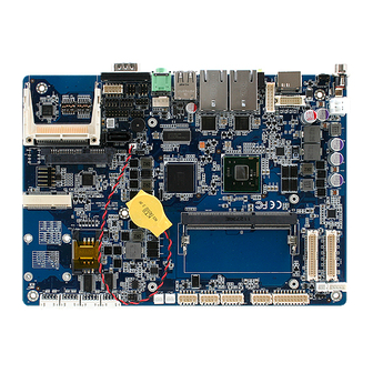
- Page 6 EBM-CDV Quick Installation Guide 2.1 Product Overview 6 EBM-CDV Quick Installation Guide...
-
Page 7: Jumper And Connector List
3 x 1 header, pitch 2.00mm JVR1 LCD backlight brightness adjustment Serial port 1/ 2 – RS232/ 422/ 485 DIP switch 6pin mode select Multi-function select DIP switch 6pin 3 x 2 header, pitch 2.00mm JHS1 Handset Speaker Out selector EBM-CDV Quick Installation Guide 7... - Page 8 Reset button JSPI1 SPI connector 4 x 2 header, pitch 2.00mm EC_Program 4 x 2 header, pitch 2.00mm EC_SPI1 SPWR1 SATA Power connector 1 2 x 1 wafer, pitch 2.00mm SATA1 Serial ATA connector 1 8 EBM-CDV Quick Installation Guide...
- Page 9 Quick Installation Guide SATA2 Serial ATA connector 2 SIM1 SIM card slot HDMI1 HDMI connector Handphone_out connector HP_OUT1 JVGA1 VGA connector 8 x 2 wafer, pitch 2.00mm EBM-CDV Quick Installation Guide 9...
-
Page 10: Setting Jumpers & Connectors
EBM-CDV Quick Installation Guide 2.3 Setting Jumpers & Connectors 2.3.1 Clear CMOS (JBAT1) Protect* Clear CMOS * Default 2.3.2 Serial port 1/ 2 RS-232/ 422/ 485 mode select (JP1/ JP2) RS-232* RS-422/ 485 * Default 10 EBM-CDV Quick Installation Guide... - Page 11 SATA Power select (JP3) * Default Signal SATA_PWR1 SATA1 P7 Serial port 1/ 2 – RS232/ 422/ 485 mode select (SW1) 2.3.4 In Serial Port 1 mode RS-232 RS-422 RS-485 In Serial Port 2 mode RS-232 RS-422 RS-485 EBM-CDV Quick Installation Guide 11...
- Page 12 AT SEL ATX SEL CF Master CF Slave Touch off Touch on Touch: 4W Touch: 5W GPIO38:L GPIO38:H GPIO39:L GPIO39:H 2.3.6 Serial port 1/ 2 pin9 signal select (JRI1/ JRI2) Ring* +12V JRI2 JRI1 * Default 12 EBM-CDV Quick Installation Guide...
- Page 13 Variation Resistor (Recommended: 4.7KΩ, >1/16W) Note: For inverters with adjustable Backlight function, it is possible to control the LCD brightness through the VR signal controlled by JBKL1. Please see the JBKL1 section for detailed circuitry information. EBM-CDV Quick Installation Guide 13...
- Page 14 EBM-CDV Quick Installation Guide 2.3.8 Handset Speaker Out selector (JHS1) * Default Signal Signal HS_MIC+ HS_MIC- HS_OUT+ HOOK 2.3.9 USB Power select (USB_PWR_SEL1) * Default Signal +V5A USB_EN +V5S 14 EBM-CDV Quick Installation Guide...
- Page 15 Quick Installation Guide 2.3.10 Power connector (PWR2) Signal Signal 2.3.11 DVI connector (DVI1) Signal PIN PIN Signal DVI_TXP2 DVI_CLK_P DVI_TXN2 DVI_CLK_N HDMI_SCLK DVI_TXP1 HDMI_SDATA DVI_TXN1 HDMI_HPD DVI_TXP0 DVI_TXN0 +V5_CRT_HDMI EBM-CDV Quick Installation Guide 15...
- Page 16 VR signal controlled by JVR1. Please see the JVR1 section for detailed circuitry information. 2.3.12.1 Signal Description – LCD Inverter Connector (JBKL1/ JBKL2) Signal Signal Description BRIGHT Vadj = 0.75V ~ 4.25V (Recommended: 4.7KΩ, >1/16W) BKL_ON LCD backlight ON/OFF control signal 16 EBM-CDV Quick Installation Guide...
- Page 17 Quick Installation Guide 2.3.13 LCD Inverter connector (JBKL2) Signal +12V 2.3.14 CPU fan connector (CPU_FAN1) Signal +V3P3S EC_TACH0 +12V EBM-CDV Quick Installation Guide 17...
- Page 18 Signal NRIB# NRTSB# NCTSB# NDSRB# COM2-3 COM2-4 COM2-1 COM2-2 2.3.16 Serial port 3/ 4/ 5/ 6 connector (COM3/ COM4/ COM5/ COM6) JCOM3 JCOM4 JCOM5 JCOM3 JCOM6 Signal PIN PIN Signal DCD# DTR# DSR# CTS# RTS# 18 EBM-CDV Quick Installation Guide...
- Page 19 Quick Installation Guide 2.3.17 LED indicator connector (JLED1) Signal PIN PIN Signal PWRBTN# +V3P3A LED2_ACT +V3P3A LED1_ACT +V3P3S HDD_LED# +V3P3S EBM-CDV Quick Installation Guide 19...
- Page 20 EBM-CDV Quick Installation Guide 2.3.18 General purpose I/O connector (DIO1) Signal PIN PIN Signal SMB_DATA SMB_CLK 20 EBM-CDV Quick Installation Guide...
- Page 21 Quick Installation Guide 2.3.19 LVDS connector (JLVDS1) Signal PIN PIN Signal +V5S +V3P3S +V5S +V3P3S DDC_DATA DDC_CLK A_DATA0 A_DATA1 A_DATA0# 11 A_DATA1# A_DATA2 A_DATA3 A_DATA2# 17 A_DATA3# LVDS1A_CLK LVDS1A_CLK# 36 +V12S +V12S EBM-CDV Quick Installation Guide 21...
- Page 22 If we boot from CRT & LCD, the resolution is fixed by CRT's resolution. If we boot from LCD only and plug the CRT in the OS, LCD works well but the CRT will have wrong resolution. CRT's resolution > LCD's resolution. Everything is fine. 22 EBM-CDV Quick Installation Guide...
- Page 23 Quick Installation Guide 2.3.21 Touch panel connector (JTOUCH) Signal PROBE NOTE: Under 4W situation UL=X+, UR=Y+, LR=Y-, LL=X- 2.3.22 USB connector 5&6 (USB56) Signal Signal USB_PP5 USB_PP4 USB_NP5 USB_NP4 +VCC_USB45 +VCC_USB45 EBM-CDV Quick Installation Guide 23...
- Page 24 EBM-CDV Quick Installation Guide 2.3.23 USB connector 7&8 (USB78) Signal Signal USB_PP7 USB_PP6 USB_NP7 USB_NP6 +VCC_USB6 +VCC_USB6 2.3.24 Battery connector (BT1) Signal VBAT 24 EBM-CDV Quick Installation Guide...
- Page 25 Quick Installation Guide 2.3.25 Audio connector (AUD1) Signal PIN PIN Signal MIC1_JD LINE1_JD FRONT_JD MIC_LIN MIC_RIN LINE1_LIN LINE1-RIN LINEOUT_L LINEOUT_R 2.3.26 AMPLIFIER_R1 (AMP_R1) Signal AMP_ROUT+ AMP_ROUT- EBM-CDV Quick Installation Guide 25...
- Page 26 EBM-CDV Quick Installation Guide 2.3.27 AMPLIFIER_L1 (AMP_L1) Signal AMP_LOUT+ AMP_LOUT- 2.3.28 VGA connector (JVGA1) Signal PIN PIN Signal CRT_R +V5_CRT_HDMI CRT_G CRT_B SDT_DDC VGA_HS VGA_VS SCK_DDC 26 EBM-CDV Quick Installation Guide...
- Page 27 Quick Installation Guide 2.3.29 LPC connector (JLPC1) Signal PIN PIN Signal LPC_AD0 +V3P3S LPC_AD1 PLTRST# LPC_AD2 LPC_LFRAME# LPC_AD3 CLK_PCI_JLPC SERIRQ +V5S +V5A LPC_LDRQ0# 2.3.30 SPI connector (JSPI1) Signal PIN PIN Signal +V3P3A_SPI SPI_R_CS# SPI_CLK SPI_SO SPI_SI SPI_HOLD# EBM-CDV Quick Installation Guide 27...
- Page 28 EBM-CDV Quick Installation Guide 2.3.31 EC_Program (EC_SPI1) Signal PIN PIN Signal +VSPI_EC EC_FSCE# EC_FSCK EC_FMISO EC_FMOSI EC_HOLD# 2.3.32 SATA Power connector 1 (SPWR1) Signal SATA_PWR1 28 EBM-CDV Quick Installation Guide...
Need help?
Do you have a question about the EBM-CDV and is the answer not in the manual?
Questions and answers