
Related Manuals for Clarke CAT120


Summary of Contents for Clarke CAT120
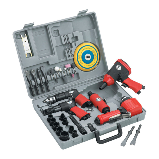
- Page 1 43 PIECE AIR TOOL KIT MODEL NO: CAT120 PART NO: 3110876 OPERATION & MAINTENANCE INSTRUCTIONS ORIGINAL INSTRUCTIONS GC 0520 - ISS 3...
-
Page 2: Introduction
INTRODUCTION Thank you for purchasing this CLARKE product. Before attempting to use this product, please read this manual thoroughly and follow the instructions carefully. In doing so you will ensure the safety of yourself and that of others around you, and you can look forward to your purchase giving you long and satisfactory service. -
Page 3: Table Of Contents
TABLE OF CONTENTS INTRODUCTION ................. 2 GUARANTEE ................2 ENVIRONMENTAL PROTECTION ..........2 TABLE OF CONTENTS ..............3 GENERAL SAFETY RULES ............4 LIST OF CONTENTS ..............6 Accessories ...................... 6 AIR SUPPLY ................. 7 Recommended Air Supply Connection ............7 THE IMPACT WRENCH ............... -
Page 4: General Safety Rules
GENERAL SAFETY RULES CAUTION: FAILURE TO FOLLOW THESE PRECAUTIONS COULD RESULT IN PERSONAL INJURY, AND/OR DAMAGE TO PROPERTY. CAUTION: THESE RULES APPLY TO ALL TOOLS IN THIS KIT. WORK ENVIRONMENT 1. Keep the work area clean and tidy. 2. Dress appropriately - Do not wear loose clothing or jewellery. Tie long hair out of the way. - Page 5 • The tool will be left unattended. • Moving to another work area. • Passing the tool to another person. 12. Never use the tool if it is defective or operating abnormally. 13. The tool should be serviced at regular intervals by qualified service personnel.
-
Page 6: List Of Contents
LIST OF CONTENTS 1 x 3/8” Reversible Drill 1 x Die Grinder c/w 1/8” & 1/4” Collets 1 x Chipping Hammer 1 x Dual Action Sander 1 x ½” Drive Impact Wrench ACCESSORIES 1 x Air Inlet Adaptor 1 x Oil Bottle 1 x Hex Key, 4 mm FOR THE DRILL: 2 x 6.35mm Slotted Screw Driver Bits: 4 &... -
Page 7: Air Supply
AIR SUPPLY WARNING: COMPRESSED AIR CAN BE DANGEROUS. ENSURE THAT YOU ARE FAMILIAR WITH ALL PRECAUTIONS RELATING TO THE USE OF COMPRESSORS AND COMPRESSED AIR SUPPLY. • Use only clean, dry, regulated compressed air as a power source for the tool. •... -
Page 8: The Impact Wrench
THE IMPACT WRENCH DESCRIPTION NO DESCRIPTION 1/2” Square Drive Anvil 1/4” BSP (Female Air Inlet) Forward / Reverse Button Handle Trigger Oil Port Speed Control Parts & Service: 020 8988 7400 / E-mail: Parts@clarkeinternational.com or Service@clarkeinternational.com... -
Page 9: Before Use
NOTE: Ensure the compressor is turned off. 1. Remove the travel plug from the 1/ 4” BSP (Female Air Inlet) as shown. 2. Pour 2-3 drops of CLARKE airline oil into the air inlet. This should be done regardless of whether or not a lubricated air supply is to be used. -
Page 10: Using The Forward/Reverse Button
USING THE FORWARD/REVERSE BUTTON WARNING: WAIT UNTIL THE ANVIL HAS STOPPED ROTATING BEFORE OPERATING THE FORWARD/REVERSE BUTTON. The Forward/Reverse button should be used as follows. 1. For normal tightening, the impact wrench should be operated in the forward (F) direction. 2. -
Page 11: Adjusting The Power
ADJUSTING THE POWER To adjust the power, set the air regulator to one of the 4 settings available. 1 (Low) - 4 (High). OPERATING THE IMPACT WRENCH WARNING: MAKE SURE THAT THE CHUCK KEY HAS BEEN REMOVED BEFORE USING THE DRILL. 1. -
Page 12: The Dual Action Sander
THE DUAL ACTION SANDER DESCRIPTION NO DESCRIPTION Trigger Locking Nut Speed Control Backing Pad Balancer 1/4” BSP (Female Air Inlet) Parts & Service: 020 8988 7400 / E-mail: Parts@clarkeinternational.com or Service@clarkeinternational.com... -
Page 13: Before Use
1. Remove the travel plug from the bottom of the tool. 2. Pour 2-3 drops of CLARKE airline oil into the air inlet. This should be done regardless of whether or not a lubricated air supply is to be used. -
Page 14: Adjusting The Speed
ADJUSTING THE SPEED Adjust the operating speed if required, by twisting the speed control. • Clockwise to increase the sanding speed. • Anticlockwise to decrease the sanding speed. USING THE SANDER 1. Place the sander on the workpiece and press down on the trigger to start the sander. -
Page 15: The Chipping Hammer
THE CHIPPING HAMMER DESCRIPTION NO DESCRIPTION Retainer spring Speed controller/air regulator Main body Outboard lug Trigger Inboard lug 1/4” BSP (Female Air Inlet) Chisel set Parts & Service: 020 8988 7400 / E-mail: Parts@clarkeinternational.com or Service@clarkeinternational.com... -
Page 16: Before Use
NOTE: Ensure the compressor is turned off. 1. Remove the travel plug from the bottom of the tool as shown. 2. Pour 2-3 drops of CLARKE airline oil into the air inlet. This should be done regardless of whether or not a lubricated air supply is to be used. -
Page 17: Adjusting The Force
It is strongly recommended that you obtain one or two spare springs, for use in the event of failure occurring during use. These are available from the Clarke Spares department. Parts & Service: 020 8988 7400 / E-mail: Parts@clarkeinternational.com or Service@clarkeinternational.com... -
Page 18: The Die Grinder
THE DIE GRINDER DESCRIPTION NO DESCRIPTION Collet nut Trigger Spindle 1/4” BSP (Female Air Inlet) Trigger Lock Parts & Service: 020 8988 7400 / E-mail: Parts@clarkeinternational.com or Service@clarkeinternational.com... -
Page 19: Before Use
NOTE: Ensure the compressor is turned off. 1. Remove the travel plug from the bottom of the tool as shown. 2. Pour 2-3 drops of CLARKE airline oil into the air inlet. This should be done regardless of whether or not a lubricated air supply is to be used. -
Page 20: Fitting The Grinding Point Or Stone
2. Remove collet nut and withdraw collet. 3. Install new collet and re-fit collet nut, (finger-tight only). FITTING THE GRINDING POINT OR STONE 1. Loosen collet nut using the spanners supplied. 2. Insert appropriate die grinding point or stone. IMPORTANT: You MUST have at least half of the length of the spindle inside the collet before use. -
Page 21: The Reversible Drill
THE REVERSIBLE DRILL DESCRIPTION DESCRIPTION Chuck Handle Trigger 1/4” BSP (Female Air Inlet) Direction control switch Parts & Service: 020 8988 7400 / E-mail: Parts@clarkeinternational.com or Service@clarkeinternational.com... -
Page 22: Before Use
4. Your air drill is now ready for use. You can fit a whip hose with a quick fit coupling if required (available from your Clarke dealer.) INSERTING/REMOVING THE DRILL BIT 1. Open the chuck jaws by inserting... -
Page 23: Direction Control Switch
DIRECTION CONTROL SWITCH WARNING: WAIT UNTIL THE CHUCK HAS STOPPED ROTATING BEFORE OPERATING THE DIRECTION CONTROL SWITCH. The direction control switch should be used as follows. 1. For normal drilling into wood, metal and masonry, the drill should be operated in the forward (F) direction. -
Page 24: After Use
• If the tool is to be stored, or is idle for longer than 24 hours, run a few drops of Clarke air line oil into the air inlet, and run the tool for 5 seconds in order to lubricate the internal parts. -
Page 25: Maintenance
DAILY • Drain water from air tank, air line and compressor. • Pour a few drops of CLARKE Air Line Oil, into the air inlet. This should be carried out regardless of whether or not the inline mini oiler is used. -
Page 26: Specifications - General
SPECIFICATIONS - GENERAL Impact Dual Action Chipping Reversible Die Grinder Wrench Sander Hammer Drill 8 cfm 2-16 cfm 3 - 16 cfm 14 cfm 6 cfm (226 l/min) (56 - 452 l/min) (84 - 452 l/min) (396 l/min) (170 l/min) Consumption Operating 90 psi... -
Page 27: Specifications - Model Specific
1770 rpm Please note that the details and specifications contained herein, are correct at the time of going to print. However CLARKE International reserve the right to change specifications at any time without prior notice. Always consult the machine’s data plate... -
Page 28: Vibration Emissions
VIBRATION EMISSIONS Employers are advised to refer to the HSE publication “Guide for Employers”. All hand held power tools vibrate to some extent, and this vibration is transmitted to the operator via the handle, or hand used to steady the tool. Vibration from about 2 to 1500 hertz is potentially damaging and is most hazardous in the range from about 5 to 20 hertz. - Page 29 could possibly increase significantly. Users must always take this into account and make their own risk assessment, using the graph above as a reference. Some tools with a high vibration value, such as impact wrenches, are generally used for a few seconds at a time, therefore the cumulative time may only be in the order of a few minutes per day.
-
Page 30: Declaration Of Conformity
DECLARATION OF CONFORMITY Parts & Service: 020 8988 7400 / E-mail: Parts@clarkeinternational.com or Service@clarkeinternational.com... -
Page 31: Notes
NOTES Parts & Service: 020 8988 7400 / E-mail: Parts@clarkeinternational.com or Service@clarkeinternational.com...
Need help?
Do you have a question about the CAT120 and is the answer not in the manual?
Questions and answers