
Related Manuals for Beckhoff CX1010 Series


Summary of Contents for Beckhoff CX1010 Series
- Page 1 Hardware documentation for CX1010 Embedded PC CX1010-0xxx CX1010-Nxxx version: 1.4 date: 2008.10.26...
-
Page 3: Table Of Contents
Table of contents Table of contents 1. Foreword Notes on the documentation Safety instructions Documentation issue status 2. Product overview Product overview System overview Basic modules Technical data Configurations Connections Battery compartment Compact Flash slot Compact Flash card Memory overview PC 104 Bus System interfaces Technical data... - Page 4 Table of contents 4. Assembly and connecting Mechanical assembly Dimensions Mechanical assembly of basic module Mechanical assembly of fieldbus connectors Inbetriebnahme Start-up procedure BIOS Setup Standard CMOS Features IDE Primary Master IDE Primary Slave Advanced BIOS Features Advanced Chipset Features Integrated Peripherals Power Management Setup IRQ Wakeup Events...
-
Page 5: Foreword
© This documentation is copyrighted. Any reproduction or third party use of this publication, whether in whole or in part, without the written permission of Beckhoff Automation GmbH, is forbidden. Embedded-PC... -
Page 6: Safety Instructions
All the components are supplied in particular hardware and software configurations appropriate for the application. Modifications to hardware or software configurations other than those described in the documentation are not permitted, and nullify the liability of Beckhoff Automation GmbH. Personnel Qualification This description is only intended for the use of trained specialists in control and automation engineering who are familiar with the applicable national standards. - Page 7 Foreword National regulations depending on the machine type Depending on the type of machine and plant in which the product is used, national regulations governing the controllers of such machines will apply, and must be observed by the operator. These regulations cover, amongst other things, the intervals between inspections of the controller.
-
Page 8: Documentation Issue Status
Foreword Documentation Issue Status Version Changes annotations to network ports changed BIOS changes added system interfaces CX1200-xxxx removed system interfaces CX1010-N070 and CX1010-N080 renamed version at start of series production 0.0.1 preliminarily version Embedded-PC... -
Page 9: Product Overview
Product overview 2. Product overview Appropriate Use The CX1010 device series is a modular control system designed for top-hat rail installation. The system is scalable, so that the required modules can be assembled and installed in the control cabinet or terminal box as required. Only switch the PC off after closing the software Before the Embedded PC is switched off, the software currently running on it should be stopped properly in order to avoid data loss on the hard disk. -
Page 10: System Overview
The system With the CX series of Embedded PCs Beckhoff has combined PC technology and modular I/O level to form a top-hat rail unit in the control cabinet. The CX1020 extends the CX product family by a version with higher CPU performance. - Page 11 PLC, Motion Control, interpolation and visualisation As a top-hat rail IPC and in conjunction with the TwinCAT software from Beckhoff, the CX1010 offers the same functionality as large Industrial PCs. In terms of PLC, up to four virtual IEC 61131 CPUs can be programmed with up to four tasks each, with a minimum cycle time of 50 µs.
- Page 12 Visualization The Beckhoff OPC server is available for interfacing with SCADA packets, if the two operating system variants “Windows CE.NET” or “Windows XP Embedded” are used. In other words, the CX1010 also offers straightforward visualization and simultaneous control in real-time on a single system.
-
Page 13: Basic Modules
Product overview Basic modules Dimensions: The basic configuration of the CX1010 includes a 64 MB Compact Flash card. One Ethernet RJ 45 interface is also part of the basic configuration. All other CX family components can be connected via the PC104 interface that is available on both sides. -
Page 14: Configurations
Product overview Configurations The Basic CPU-Module can be ordered with different hardware and software variations. As operating systems there are "Windows CE.NET" and "Windows XP Embedded" available. The TwinCAT automation software transforms a CX1020 system into powerful PLC and Motion Control system that can be operated with or without visualisation. The order identifier of the basic CPU module is derived as follows: Following CX1020 configurations are available: TwinCAT... -
Page 15: Connections
Product overview Connections The basic CPU module is available with different hardware and software options. It is supplied from the power supply unit, so that only the connections are described here. Basic CPU module with 2 Ethernet RJ 45 interfaces: RJ 45 interface (socket): Assignment of the RJ45 interface: Signal... - Page 16 Product overview Operating system perspective: The operating system only sees the connections for the network interface. The internal connection via the PC104 bus extension is shown as the second interface. If no expansion module is connected, the line is reported as not connected.
-
Page 17: Battery Compartment
Only. Use of Another Battery May Present A Risk Of Fire Or Explosion. WARNING, Battery may explode if mistreated. Do Not Recharge, Disassemble or Dispose of in fire. Note The battery must be changed every 5 years. Spare batteries can be ordered from Beckhoff Service. Embedded-PC... -
Page 18: Compact Flash Slot
Product overview Compact Flash slot A Compact Flash slot is provided at the front of module. This enables an additional Compact Flash memory medium (format I or II) to be operated. The change - in case of the Basic CPU module CF slot - is only allowed while the system is powered down - otherwise the system could crash. -
Page 19: Compact Flash Card
Warning It is recommended only use CF cards supplied by Beckhoff Automation GmbH. The CF cards are made for industrial use. They possess a higher number of read / write cycles and an enhance temperature range (up to + 85°C). -
Page 20: Memory Overview
Product overview Adapter RAM Hardware address overview available memory addresses CX1020: D0000-DFFFF (hex) Base Address End Address Access (hex) (hex) Size(Bytes)(hex) Type Description D0000 D0FFF 1000 CX1100-0002/3 Dual Ported RAM D1000 D100F CX1100 Auxiliary Control Block( LCD Display, misc. registers) D1010 D101F CX1100-0900 UPS Control Block... - Page 21 Product overview Note Two connection modules (master or slave) can be used simultaneously. If more than two connections are needed call Beckhoff Automation GmbH for further information. Embedded-PC...
-
Page 22: Pc 104 Bus
Product overview PC/104 Bus The PC 104 bus is a standardized bus with 104 ISA signals for compact embedded systems. For the functionality of the CX1020 modules eight further signals have been added ( here marked with color). Pin assignment of 16 Bit PC 104 Bus: Number Row A Row B... - Page 23 Product overview 1. B10 and C19 are key locations. 2. Signal timing and function are as specified in ISA specification. 3. Signal source/sink current differ from ISA values. 4. in the specification the pins are counted from 0 to 19 Assignment on the 8 additional pins Pin number (yellow fields) Row C...
-
Page 24: System Interfaces
Product overview System interfaces Technical Data Dimensions: Embedded-PC... - Page 25 CX1010-N060 Ethernet-interface The CX1010-N010 option can be connected to Beckhoff Control Panels or standard monitors with DVI or VGA input via the DVI or USB interfaces.Devices such as printer, scanner, mouse, keyboard, mass storage, CR-RW etc. can be connected via the USB 2.0 interfaces. Multimedia capability is realized via the CX1010-N020 audio interface. The modules CX1010-N030 and CX1010-N040 offer a total of four serial RS232 interfaces with a maximum transfer speed of 115 kbaud.
- Page 26 Product overview CX1010-N030 CX1010-N031 Technical data CX1010-N010 CX1010-N020 CX1010-N040 CX1010-N041 Interfaces 1 x DVI + Line IN, 1 x COM1+2, RS232 1 x COM1+2, RS422/RS485 2 x USB 2.0 MIC IN, 1 x COM3+4, RS232 1 x COM3+4,RS422/RS485 max. 100 mA Line OUT per port Connection type...
-
Page 27: Connectors Cx1010-N010
The DVI-I interface transfers analog and digital data and is suitable for connection to analog graphics cards with 15 pin D-Sub connector and digital graphics cards with DVI-D output. The resolution at the screen or the Beckhoff Control Panel depends on the distance (maximum 5 m). - Page 28 Product overview Assignment cross Assignment Analog Red Video Out Analog Green Video Out Analog Blue Video Out Analog Horizontal Sync Resolution at the monitor: Resolution in Pixel Distance of the interface from the monitor 1600 x 1200 1280 x 1024 1024 x 768 800 x 600 640 x 480...
-
Page 29: Connectors Cx1010-N020
Product overview CX1020-N020 connections This system interface provides the audio interface for the CX1020 system. Two inputs, "LINE IN" and "MIC IN", are available. The "LINE OUT" connection is used as output for audio signals. It can also be used for connecting headphones with a maximum output of 200 mW. - Page 30 Product overview CX1010-N030/40 connections The CX1010-N030 system interface features two RS232 interfaces, COM1 and COM2 (9 pin Sub-D plug connector). If there is need for more than two serial interfaces two further RS232 interfaces, COM3 and COM4 (9 pin Sub-D plug connector) can be added to the system via the system interface CX1010-N40.
- Page 31 Product overview CX1020-N031/41 connections The CX1010-N031 system interface features two RS422 / RS 485 interfaces, COM1 and COM2 (9 pin Sub-D plug connector). If there is need for more than two serial interfaces two further RS422 / RS485 interfaces, COM3 and COM4 (9 pin Sub-D plug connector) can be added to the system via the system interface CX1010-N41.
- Page 32 Product overview Setting the interface parameter If the system interface CX1010-N031/N041 resides at the end of the CX1010-system block, it is easy to access the dip switches. The dip switches for the configuration of the RS485/422 interfaces can be found at the left side of the module.
- Page 33 Product overview Auto send on Always send on Auto receive on Always receive on Term on Term on RS485 without Echo, Drop-Point ( without Termination) Status Function Echo on Echo off Auto send on Always send on Auto receive on Always receive on Term on Term on...
- Page 34 Product overview Note The system interface CX1010-N31 can only be used instead and not at the same time with system interface CX1010-N030. The system interface CX1010-N41 can only be used instead and not at the same time with system interface CX1010-N040. Embedded-PC...
-
Page 35: Connectors Cx1010-N060
Product overview CX1020-N060 connections The CX1010-N060 system interface provides a further network interface. It can only be used if the CX1100-0004 power supply unit is not connected, since in this case the only internal interface available is used for connecting the Ethernet port. - Page 36 Product overview Incorrect mounting position: The interface is located to the left of the CPU module, in series with the other system interfaces. Warning The connected network cable must not have a length of more than 15 meters! Note The CX1010-N060 system interface can only be used in place of the CX1100-0004 power supply unit, not at the same time.
-
Page 37: Power Supply Units
Terminals can be connected, or via CX1100-0003, which in addition to the Bus Terminals enables the connection of Extension Box IExxxx type Beckhoff Fieldbus Box modules. The option to connect Bus Terminals or a fieldbus Box creates a control system with a very variable, expandable I/O level with large signal variety. The I/O data are stored in a DPRAM, which is accessible by the CPU via the system bus. -
Page 38: Technical Data Cx1100-0001
Product overview Technical data CX1100-0001 Dimensions: One of power supply modules can be selected for a CX10x0 system. The power supply of all other system components is ensured via the internal PC104 bus; no separate supply lines are required. However, the CX1100 components offer further important characteristics that go beyond a pure power supply: an integrated NOVRAM enables the fail-safe storage of process data, an LCD display with two lines of 16 characters each is used for displaying system and user messages. -
Page 39: Technical Data Cx1100-0002
Product overview Technical data CX1100-0002 Dimensions: Technical data CX1100-0002 Power supply 24 V (-15%/+20%) To meet the UL requirements use a 4 A fuse or a power supply that has to satisfy NEC class 2! Dielectric strength 500 V (supply / internal electronics) Max. -
Page 40: Technical Data Cx1100-0012
Product overview Technical data CX1100-0012 Dimensions: Technical data CX1100-0012 Power supply 24 V (-15%/+20%) To meet the UL requirements use a 4 A fuse or a power supply that has to satisfy NEC class 2! Dielectric strength 500 V (supply / internal electronics) Max. -
Page 41: Technical Data Cx1100-0003
Product overview Technical data CX1100-0003 Dimensions: Technical data CX1100-0003 Power supply 24 V (-15%/+20%) To meet the UL requirements use a 4 A fuse or a power supply that has to satisfy NEC class 2! Dielectric strength 500 V (supply / internal electronics) Max. -
Page 42: Technical Data Cx1100-0013
Product overview Technical data CX1100-0013 Dimensions: Technical data CX1100-0013 Power supply 24 V (-15%/+20%) To meet the UL requirements use a 4 A fuse or a power supply that has to satisfy NEC class 2! Dielectric strength 500 V (supply / internal electronics) Max. -
Page 43: Technical Data Cx1100-0004
Product overview Technical data CX1100-0004 Dimensions: With the CX1100-0004 power supply EtherCAT Terminals can be connected to the CX1020-System. With CX1100- 0004 the I/O data are stored directly in the main memory of the CPU; a DPRAM is no longer required. The CX1100- 0004 power supply unit for EtherCAT Terminals can only be connected in conjunction with the basic CX1020 CPU module. -
Page 44: Technical Data Cx1100-0014
Product overview Technical data CX1100-0014 Dimensions: The CX1100-0014 power supply is designed for CX1030. With the CX1100-0014 power supply EtherCAT Terminals can be connected to the CX10x0-System. With CX1100- 0004 the I/O data are stored directly in the main memory of the CPU; a DPRAM is no longer required. The CX1100- 0014 power supply unit for EtherCAT Terminals can not be connected in conjunction with the basic CX1000 CPU module. -
Page 45: Connectors Cx1100-0001
Product overview CX1100-0001 connections This power supply unit does not have an I/O interface. The power supply is therefore connected through the 5-pin open pluggable connector. The power supply unit supplies all further system components with a voltage of 24 V DC (- 15 %/+20%) via the PC104 bus. -
Page 46: Connectors Cx1100-00X2
Product overview CX1100-00x2 connections This power supply unit is equipped with an I/O interface, which permits connection of the Beckhoff Bus Terminals. The power is supplied via the upper spring-loaded terminals labelled “24V” and “0V”. The supply voltage feeds the CX system and supplies a voltage of 24 V DC (-15 %/+20%) to the Bus Terminals via the K-Bus. -
Page 47: Connectors Cx1100-00X3
This power supply unit permits not only the connection of the Beckhoff Bus Terminals, but also the serial connection of the Beckhoff fieldbus box modules of the type extension box IExxxx. The power is supplied via the upper spring- loaded terminals labeled “24V” and “0V”. -
Page 48: Connectors Cx1100-00X4
Product overview CX1100-00x4 connections This power supply unit is equipped with an I/O interface, which permits connection of the Beckhoff Bus Terminals. The power is supplied via the upper spring-loaded terminals labeled “24V” and “0V”. The supply voltage feeds the CX system and supplies a voltage of 24 V DC (-15 %/+20%) to the Bus Terminals via the E-Bus. -
Page 49: Lcd Display
Product overview LC Display The LC Display of the power supply units has two rows of 16 characters each and is used for displaying system and user messages. "Index-Group/Offset" Specification for the LC Display ADS Port 300 Index Data Phys. Def. -
Page 50: Transport
4. Please keep the associated paperwork. It contains important information for handling the unit. 5. Check the contents for visible shipping damage. 6. If you notice any shipping damage or inconsistencies between the contents and your order, you should notify Beckhoff Service. Warning Danger of damage to the unit! During transport in cold conditions, or if the unit is subjected to extreme temperature swings, condensation on and inside the unit must be avoided. -
Page 51: Assembly And Connecting
The overall width of the application is made up of the individual modules. With a height of 100 mm, the module dimensions exactly match those of the Beckhoff Bus Terminals. Together with the lowered connector surfaces, this means that it can be used in a standard terminal box with a height of 120 mm. - Page 52 Assembly and connecting CX1010-N0x0 System interfaces: Embedded-PC...
- Page 53 Assembly and connecting CX1100-000x power supply units: CX1100-0001 power supply without I/O-interface CX1100-0002 power supply with I/O-interface (K-Bus-connection) Embedded-PC...
- Page 54 Assembly and connecting Abmessungen in mm: 39 x 100 x 91 CX1100-0003 power supply with I/O-interface (K-Bus-connection and IP Link) Abmessungen in mm: 58 x 100 x 91 CX1100-0004 power supply with I/O-interface (E-Bus-connection) Embedded-PC...
- Page 55 Assembly and connecting CX1100-09x0 UPS Modules: CX1100-0900 CX1100-0910 Embedded-PC...
- Page 56 Assembly and connecting CX1100-0920 Embedded-PC...
- Page 57 Assembly and connecting CX1500-Mxxx und CX1500-Bxxx fieldbus connections All modules for the fieldbus connections (master and slave) have the dimensions (W x H x D) 38 mm x 100 mm x 91 CX1500-Bxxx Embedded-PC...
- Page 58 Assembly and connecting CX1500-Mxxx Embedded-PC...
-
Page 59: Mechanical Assembly Of Basic Module
Assembly and connecting Mechanical assembly of the basic module The installation of the modules takes place in three steps: 1. The sequence of the modules The basic CPU module with system interfaces, which are factory-installed on the left side, is extended with the power supply unit on the right and with the fieldbus connection (master or slave) left side if available. - Page 60 Assembly and connecting Then fix the CX1010 block on the top hat-rail using the latching straps. You should hear a soft click. Do not force the module or apply excessive pressure! Only apply pressure at insensitive points of the housing (edges). Never apply pressure on the display, the buttons or movable parts of the CX10x0 system.
- Page 61 Assembly and connecting Incorrect installation positions: The CX1010 system must not be operated vertically on the top-hat rail. A vertical position would lead to insufficient CPU ventilation, since the ventilation openings are located on the top and bottom of the housing. Installation of the system on its side would also lead to inadequate ventilation.
-
Page 62: Mechanical Assembly Of Fieldbus Connectors
Assembly and connecting Mechanical installation of the fieldbus connection Installation of a fieldbus connection involves several steps: 1. Removing the cover of the basic CX1020 module In order to be able to connect the fieldbus to the basic CX1020 module, the cover of the basic CX1000/CX1020 module has to be removed first. - Page 63 Assembly and connecting 3. Install cover If the connection area does not have a closing cover on the left-hand side, the cover that was previously removed should be pressed over the connections until it audibly engages. Note: If the CX1000/CX1020 configuration is not positioned on the top-hat rail, it is possible to connect the assembly with the CX1000/CX1020 configuration first and then latch the whole module onto the top-hat rail.
-
Page 64: Inbetriebnahme
Assembly and connecting Inbetriebnahme Switching the PC on and off Switching on The power supply for the basic CPU module comes from the power supply unit. The basic CPU module starts automatically when the power supply unit is connected to the mains. Switching on for the first time When you switch on the PC for the first time, the pre-installed operating system (optional) will be started. -
Page 65: Bios Setup
Assembly and connecting Note on using the setup Warning Beckhoff Automation GmbH supplies the CX1020 systems pre-configured, which means they are READY FOR USE! The BIOS settings should only be modified by appropriately trained staff. Under Windows CE the BIOS should not be changed at all, since the operating system is adapted to the hardware configuration. - Page 66 Assembly and connecting Exit Without Saving Quit setup without saving the settings. Setting: Y (Please note: enter Z with German keyboard). Embedded-PC...
-
Page 67: Standard Cmos Features
Assembly and connecting Standard CMOS Features This menu is used for setting the date, time, hard disks, graphics mode and start-up behaviour. At the same time, information about the memory configuration determined by the system is provided. The memory configuration information cannot be changed. - Page 68 Assembly and connecting detected by the POST. Extended Memory Available memory from the first MB to the maximum memory capacity. Total Memory This is the total of base memory, extended memory and other memory. Embedded-PC...
-
Page 69: Ide Primary Master
Assembly and connecting IDE Primary Master This menu is used for setting the data of the first hard disk connected to the IDE bus as master. The hard disk data (size, number of cylinders, heads, sectors, pre-compensation and home position of the heads when the disk is switched off) are displayed automatically for the connected hard disk. - Page 70 Assembly and connecting LARGE Auto The following parameters are automatically determined and displayed. Capacity Storage capacity of the hard disk. This value is calculated from the individual hard disk parameters. Cylinder Define or set the number of cylinders. Depending on the BIOS version and the manufacturer it varies between 1,024 and 16,384 cylinders.
-
Page 71: Ide Primary Slave
Assembly and connecting IDE Primary Slave This menu is used for setting the data of the first hard disk connected to the IDE bus as master. The hard disk data (size, number of cylinders, heads, sectors, pre-compensation and home position of the heads when the disk is switched off) are displayed automatically for the connected hard disk. - Page 72 Assembly and connecting LARGE Auto The following parameters are automatically determined and displayed. Capacity Storage capacity of the hard disk. This value is calculated from the individual hard disk parameters. Cylinder Define or set the number of cylinders. Depending on the BIOS version and the manufacturer it varies between 1,024 and 16,384 cylinders.
-
Page 73: Advanced Bios Features
Assembly and connecting Advanced BIOS Features This menu is used for setting the data of the first hard disk connected to the IDE bus as master. The hard disk data (size, number of cylinders, heads, sectors, pre-compensation and home position of the heads when the disk is switched off) are displayed automatically for the connected hard disk. - Page 74 Assembly and connecting HDD-1 (hard disc 2) ZIP100 (Zip-Drive) USB-FDD (USB-Floppy) USB-ZIP (USB Zip-Drive) USB-CDROM (USB CDROM) LAN (network) Disabled (disabled) Third Boot Device This setting is used for booting, if the first and second boot device are not available. Options: ...
- Page 75 Assembly and connecting Full Screen Logo This option can be used to specify that the start logo should fill the whole screen during booting, thereby hiding the start data. Setting options: Enabled, Disabled Embedded-PC...
-
Page 76: Advanced Chipset Features
Assembly and connecting Advanced Chiset Features This menu offers the possibility to change memory settings. Be careful: wrong settings here can risk the system stability. Phoenix – AwardBIOS CMOS Setup Utility Advanced Chipset Features CPU Frequency [AUTO] Item Help Memory Frequency 100 MHz CAS Latency [AUTO]... - Page 77 Assembly and connecting Onboard Audio The onboard audio controller can be switched on or off here. Setting options: Auto, Disabled . Onboard USB 2.0 The board contains a USB 2.0 chipset with support for USB 2.0. The option can be switched on or off here. Onboard IDE If this option is enabled, the IDE controller of the board can be used.
-
Page 78: Integrated Peripherals
Assembly and connecting Integrated Peripherals This menu is used for setting the system interfaces. Phoenix – AwardBIOS CMOS Setup Utility Integrated Peripherals Master Drive PIO Mode [Auto] Item Help Slave Drive PIO Mode [Auto] IDE Primary Master UDMA [Auto] IDE Primary Slave UDMA [Auto] IDE DMA transfer access [Enabled]... - Page 79 Assembly and connecting IDE Primary Slave UDMA This option is used to configure the Ultra-DMA/33 mode of your hard disk. Setting options: Auto, Enabled, Disabled. The option should be set to Enabled. IDE DMA Transfer access This option is used to set the DMA transfer function of the IDE-hard disk. Options are: Enabled, Disabled. IDE HDD Block Mode This option is used to activate block mode for IDE hard disks.
-
Page 80: Power Management Setup
Assembly and connecting Power Management Setup This menu is used for power management settings. Phoenix – AwardBIOS CMOS Setup Utility Power Management Setup ACPI Suspend Type [S1(POS)] Item Help Power Management [Disabled] ** PM Timers ** Standby Mode Disabled Suspend Mode Disabled HDD Power Down [Disabled]... -
Page 81: Irq Wakeup Events
Assembly and connecting IRQ Wakeup Events Here you can set the interrupts for events system wakeup if system is in suspend mode. Phoenix – AwardBIOS CMOS Setup Utility IRQ Wakeup Events IRQ1 (Keyboard) [OFF] Item Help IRQ3 (COM 2) [OFF] IRQ4 (COM 1) [OFF]... - Page 82 Assembly and connecting IRQ12 (PS/2 Mouse) [ON /OFF] IRQ13 (Coprocessor) [ON /OFF] IRQ14 (Hard Disk) [ON /OFF] IRQ15 (Reserved) [ON /OFF] Embedded-PC...
-
Page 83: Pnp / Pci Configuration
Assembly and connecting PnP/PCI Configurations This menu is used for configuring the PCI bus and Plug and Play Management. Phoenix – AwardBIOS CMOS Setup Utility PnP/PCI Configurations PNP OS Installed [Yes] Item Help Init Display First [Onboard] Reset Configuartion Data [Enabled] Resources Controlled By [Manual]... -
Page 84: Irq Resources
Assembly and connecting IRQ Resources This menu is used for disabling interrupts for free allocation to PCI slots. Phoenix – AwardBIOS CMOS Setup Utility IRQ Resources IRQ-7 assigned to [PCI Device] Item Help IRQ-12 assigned to [PCI Device] IRQ-15 assigned to [PCI Device] ↑... -
Page 85: Dma Resources
Assembly and connecting DMA Resources Each DMA Channel (0, 1, 3, 5, 6 und 7) can be assigned to one BUS (PCI/ISA PnP oder ISA). Phoenix – AwardBIOS CMOS Setup Utility DMA Resources DMA-0 assigned to [PCI/ISA PnP] Item Help DMA-1 assigned to [PCI/ISA PnP] DMA-3 assigned to... -
Page 86: Memory Resources
Assembly and connecting Memory Resources This menu can be used to specify a memory area for peripherals. The area is precisely defined through a base address and length. Phoenix – AwardBIOS CMOS Setup Utility Memory Resources Reserved Base [D000] Item Help Reserved Memory Length [64K]... -
Page 87: Pc Health Status
Assembly and connecting PC Health Status This menu is used for displaying the settings for CPU and motherboard temperatures, power supply, and fan speed. Phoenix – AwardBIOS CMOS Setup Utility PC Health Status Shutdown Temperature [Disabled] Item Help Temp. CPU 70°C Temp. -
Page 88: Error Handling And Diagnostics
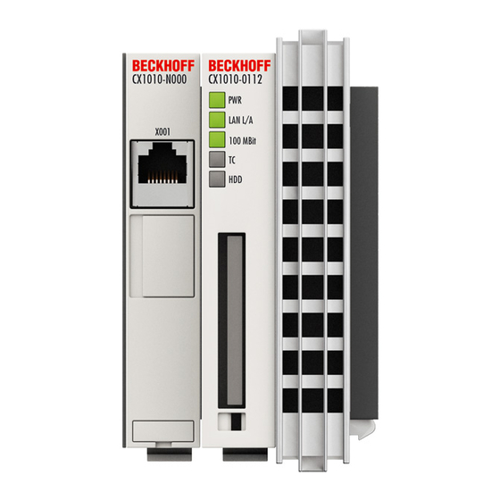
Error handling and diagnostics 5. Error handling and diagnostics CPU basic module LEDs Basic CPU-Module Anzeige Bedeutung Power supply The Power LED comes on when the device is connected to a live power supply unit. LAN L/A LAN L/A (LINK/ ACTIVITY), lights green in network is connected. Flashes green by net work activity. -
Page 89: Power Supply Units
Error handling and diagnostics Power supply units CX1100-0001 power supply LEDs Display Meaning Power The LED lights up green when the power supply is correct, but red if there is a short circuit. Embedded-PC... -
Page 90: Led Cx1100-0002
Error handling and diagnostics CX1100-0002 power supply LEDs After switching on, the power supply immediately checks the connected Bus Terminal configuration. Error-free start- up is signalled by the red "I/O ERR” LED being extinguished. If the ”I/O ERR" LED blinks, an error in the area of the terminals is indicated. - Page 91 Error handling and diagnostics K-Bus error in register Exchange the nth bus terminal 5 pulses communication with Bus Terminal n Checksum error in Flash Revert to the manufacturer’s setting 9 pulses program n (n>0) Bus Terminal n is not Revert to the manufacturer's setting which consistent with the will clear the boot project.
-
Page 92: Led Cx1100-0012
Error handling and diagnostics CX1100-0012 power supply LEDs After switching on, the power supply immediately checks the connected Bus Terminal configuration. Error-free start- up is signaled by the red "I/O ERR” LED being extinguished. If the ”I/O ERR" LED blinks, an error in the area of the terminals is indicated. - Page 93 Error handling and diagnostics K-Bus error in register Exchange the nth bus terminal 5 pulses communication with Bus Terminal n Checksum error in Flash Revert to the manufacturer’s setting 9 pulses program n (n>0) Bus Terminal n is not Revert to the manufacturer's setting which consistent with the will clear the boot project.
-
Page 94: Led Cx1100-0003
Error handling and diagnostics CX1100-0003 power supply LEDs After switching on, the power supply immediately checks the connected Bus Terminal configuration. Error-free start- up is signalled by the red "I/O ERR” LED being extinguished. If the ”I/O ERR" LED blinks, an error in the area of the terminals is indicated. - Page 95 Error handling and diagnostics is connected. K-Bus error in register Exchange the nth bus terminal 5 pulses communication with Bus Terminal n Checksum error in Flash Revert to the manufacturer’s setting 9 pulses program n (n>0) Bus Terminal n is not Revert to the manufacturer's setting which consistent with the will clear the boot project.
- Page 96 Error handling and diagnostics Note If an error occurs on both terminal busses (K-Bus and IP-Link-Bus) the error on K-Bus is reported at first. The IP-Link-Bus error is reported as second. Both error codes are introduced by their typical blink signal. Embedded-PC...
-
Page 97: Led Cx1100-0013
Error handling and diagnostics CX1100-0013 power supply LEDs After switching on, the power supply immediately checks the connected Bus Terminal configuration. Error-free start- up is signaled by the red "I/O ERR” LED being extinguished. If the ”I/O ERR" LED blinks, an error in the area of the terminals is indicated. - Page 98 Error handling and diagnostics is connected. K-Bus error in register Exchange the nth bus terminal 5 pulses communication with Bus Terminal n Checksum error in Flash Revert to the manufacturer’s setting 9 pulses program n (n>0) Bus Terminal n is not Revert to the manufacturer's setting which consistent with the will clear the boot project.
- Page 99 Error handling and diagnostics Note If an error occurs on both terminal busses (K-Bus and IP-Link-Bus) the error on K-Bus is reported at first. The IP-Link-Bus error is reported as second. Both error codes are introduced by their typical blink signal. Embedded-PC...
-
Page 100: Led Cx1100-0004
Error handling and diagnostics CX1100-0004 power supply LEDs Display Meaning power supply The LED lights up green when the power supply is correct, but red if there is a short circuit. E-Bus is not connected E-Bus is connected / no data traffic on E-bus blink E-Bus is connected / data traffic on E-bus Indicates the state of the EtherCAT bus:... -
Page 101: Led Cx1100-0014
Error handling and diagnostics CX1100-0014 power supply LEDs Display Meaning power supply The LED lights up green when the power supply is correct, but red if there is a short circuit. E-Bus is not connected E-Bus is connected / no data traffic on E-bus blink E-Bus is connected / data traffic on E-bus Indicates the state of the EtherCAT bus:... -
Page 102: Faults
If servicing is required, please quote the project number of your PC (on the type plate). Please contact your Beckhoff branch office or representative for local support and service on Beckhoff products! The addresses of Beckhoff's branch offices and representatives round the world can be found on her internet pages: http://www.beckhoff.com You will also find further documentation for Beckhoff components there. -
Page 103: Removal And Disposal
Removal and disposal 6. Removal and disposal Removal and disposal A CX10x0 hardware configuration is dismantled in 2 stages: 0. Switching off and disconnecting the power supply Before a CX10x0 system can be dismantled, the system should be switched off, and the power supply should be disconnected. - Page 104 Removal and disposal 2. Separating the individual modules 2.1. Separating the power supply unit, the CX10x0 CPU and other components Place the CX10x0 block onto a suitable support with the front facing down. Then insert a flat screwdriver with dimensions 1.0 x 5.5 x 150 mm into the locking mechanism, and then operating the slider by turning it about 90 degrees.
- Page 105 Removal and disposal Only modules (CPU, fieldbus connections and UPS modules) that can be separated non-destructively feature a release device. Modules that cannot be separated only feature a marking point (with or without red paint seal). Applying force to these elements will destroy them. Warning Forcibly opening the module housing (e.g.
-
Page 106: Appendix
Appendix 7. Appendix Accessories Compact flash cards order number Description CX1900-0023 1 GByte compact flash card type I CX1900-0025 2 GByte compact flash card type I CX1900-0027 4 GByte compact flash card type I Connectors and Adaptors order number Description CX1900-0101 DVI-to-VGA passive Adaptor for connecting a standard desktop VGA monitor to the CX1000 system... -
Page 107: Certifications
All products of the Embedded PC family are CE, UL and GOST-R certified. Since the product family is continuously developed further, we are unable to provide a full listing here. The current list of certified products can be found on the Embedded PC certificates web page or at www.beckhoff.com under Embedded PC. Embedded-PC... -
Page 108: Support And Service
Beckhoff's branch offices and representatives Please contact your Beckhoff branch office or representative for local support and service on Beckhoff products! The addresses of Beckhoff's branch offices and representatives round the world can be found on her internet pages: http://www.beckhoff.com You will also find further documentation for Beckhoff components there.
Need help?
Do you have a question about the CX1010 Series and is the answer not in the manual?
Questions and answers