
Related Manuals for Bailey infi 90 INNIS01


Summary of Contents for Bailey infi 90 INNIS01
- Page 1 Network Interface Slave Module (INNIS01)\ Network Processing Module (INNPM11) Process Control and Automation Solutions from Elsag Bailey Group...
- Page 2 The information contained in this document is subject to change without notice. Elsag Bailey, its affiliates, employees, and agents, and the authors and contributors to this publication specif- ically disclaim all liabilities and warranties, express and implied (including warranties of merchantability and...
- Page 3 Preface The INNIS01 Network Interface Slave Module (NIS) and the INNPM11 Network Processing Module (NPM) make up a pro- cess control unit interface. This process control unit interface provides control modules in a process control unit with access ® to an INFI-NET communication system.
- Page 4 ® List of Effective Pages Total number of pages in this instruction is 57, consisting of the following: Page No. Change Date Preface Original List of Effective Pages Original iii through vii Original 1-1 through 1-7 Original 2-1 through 2-4 Original 3-1 through 3-13 Original...
-
Page 5: Table Of Contents
Table of Contents Page SECTION 1 - INTRODUCTION ....................1-1 OVERVIEW ........................1-1 INTENDED USER ......................1-1 PROCESS CONTROL UNIT INTERFACE DESCRIPTION ..........1-1 INNIS01 NETWORK INTERFACE SLAVE MODULE............1-1 INNPM11 NETWORK PROCESSING MODULE...............1-2 FEATURES........................1-3 INSTRUCTION CONTENT .....................1-4 HOW TO USE THIS INSTRUCTION ................1-4 GLOSSARY OF TERMS AND ABBREVIATIONS .............1-5 REFERENCE DOCUMENTS..................1-5 DOCUMENT CONVENTIONS ..................1-5 NOMENCLATURE ......................1-6... - Page 6 ® Table of Contents (continued) Page SECTION 3 - INSTALLATION (continued) INNPM11 MODULE INSTALLATION................3-11 SECTION 4 - OPERATING PROCEDURES................4-1 INTRODUCTION ......................4-1 INNIS01 NETWORK INTERFACE SLAVE MODULE START-UP PROCEDURES ....4-1 Event Counters ..................... 4-1 Error Counters ...................... 4-1 INNPM11 NETWORK PROCESSING MODULE LEDs AND CONTROLS ......
- Page 7 Table of Contents (continued) Page APPENDIX B - NICL01 TERMINATION MODULE CONFIGURATION ........B-1 INTRODUCTION......................B-1 APPENDIX C - WARM FAILOVER FEATURE................C-1 INTRODUCTION......................C-1 OPERATION ........................ C-1 PERFORMANCE ......................C-2 RESTRICTIONS ......................C-3 List of Figures Title Page 1-1. Redundant Process Control Unit Interfaces ............1-2 3-1.
- Page 8 ® List of Tables (continued) Title Page 4-1. INNPM11 Module Status LED States ..............4-3 5-1. INNIS01 Module Error Codes ................. 5-1 5-2. INNPM11 Module Error Codes ................5-2 5-3. INNIS01 Module Edge Connector P1 Pin Assignments ..........5-3 5-4. INNIS01 Module Edge Connector P2 Pin Assignments ..........
- Page 9 Safety Summary GENERAL Equipment Environment WARNINGS All components, whether in transportation, operation or storage, must be in a noncorrosive environment. Electrical Shock Hazard During Maintenance Disconnect power or take precautions to insure that contact with energized parts is avoided when servicing. Special Handling This module uses electrostatic sensitive devices.
- Page 10 ® Trademarks and Registrations Registrations and trademarks used in this document include: ® INFI 90 Registered trademark of Elsag Bailey Process Automation ® INFI-NET Registered trademark of Elsag Bailey Process Automation ® Network 90 Registered trademark of Elsag Bailey Process Automation...
-
Page 11: Section 1 - Introduction
SECTION 1 - INTRODUCTION OVERVIEW INFI-NET is a unidirectional, high-speed serial data highway shared by all INFI 90 OPEN nodes. INFI-NET provides sophisti- cated interfaces for data exchange. This process control unit interface is made up of state-of-the-art INFI 90 OPEN modules. INTENDED USER Personnel installing, operating or maintaining the process con- trol unit interface should read this instruction before perform-... -
Page 12: Innpm11 Network Processing Module
INTRODUCTION ® O IS IN F I-N E T L O OP P C U P R O C E S S C O N T RO L U N IT N IS N P M N P M N IS C O N TRO LW AY M FP ...U P TO 3 2 M O D U L E S... -
Page 13: Features
INTRODUCTION The NPM module is a single printed circuit board that occupies the slot adjacent to the NIS module in the module mounting unit. The circuit board contains microprocessor based commu- nication circuitry that enables it to interface with the NIS mod- ule and all Controlway modules. -
Page 14: Instruction Content
Maintenance Contains a maintenance schedule for the modules. Explains how to replace the modules. Repair/Replacement Procedures Explains the customer training Elsag Bailey provides and Support Services information about ordering replacement parts. Appendices Provide information termination... -
Page 15: Glossary Of Terms And Abbreviations
GLOSSARY OF TERMS AND ABBREVIATIONS Table lists the terms and abbreviations used in this instruction that unique Elsag Bailey Process Automation. Table 1-1. Glossary of Terms and Abbreviations Term Definition Checksum A value computed from a data stream by treating each element as a number and computing a sum of the elements. -
Page 16: Nomenclature
INTRODUCTION ® NOMENCLATURE Table lists the modules that make up the process control unit interface and other associated equipment. Table 1-3. Nomenclature Nomenclature Description IEMMU01/02/04 Module mounting unit IEMMU11/12/21/22 Module mounting unit Process control unit interface. Requires: INNIS01 Network interface slave module INNPM11 Network processing module NFTP01... - Page 17 INTRODUCTION Table 1-4. Specifications (continued) Property Characteristic/Value All INFI-NET Communication Modules Electromagnetic/radio Values not available at this time. Keep cabinet doors closed. Do not use frequency interference communication equipment any closer than 2 meters from the cabinet. Ambient temperature 0° to 70°C (32° to 158°F) Relative humidity 5% to 90% up to 55°C (131°F) noncondensing 5% to 40% above 55°C (131°F) noncondensing...
-
Page 18: Section 2 - Description And Operation
SECTION 2 - DESCRIPTION AND OPERATION INTRODUCTION INFI-NET is a unidirectional, high-speed serial data highway that can be used by all INFI 90 OPEN modules. The INNIS01 Network Interface Slave Module (NIS) and the INNPM11 Net- work Processing Module (NPM) make up the process control unit interface. -
Page 19: Messages
DESCRIPTION AND OPERATION ® Exception reports can have data values in the following for- mats: Digital, analog, and status report. Exception reports are time-stamped to reflect their processing sequence. The maximum and minimum report time parameters insure that an exception report is generated for static or rapidly changing data. -
Page 20: Message Transmission
DESCRIPTION AND OPERATION bytes. The control field contains time of origination, sequence, source, size, circulation count, message type, destinations, and checksum. The NIS module increments the circulation count field of all incoming messages. When a message count field exceeds 255, the message is discarded. -
Page 21: Innpm11 Network Processing Module
DESCRIPTION AND OPERATION ® INNPM11 NETWORK PROCESSING MODULE The NPM module holds the exception report routing database and directs the operation of the process control unit interface. It acts as the translator between the INFI-NET loop and the Controlway. It communicates directly to the NIS module on the I/O expander bus. -
Page 22: Section 3 - Installation
SPECIAL HANDLING Observe these steps when handling electronic circuitry: NOTE: Always use Elsag Bailey's field static kit (part number 1948385?1 - consisting of two wrist straps, ground cord assembly, alligator clip, and static dissipating work surface) when working with the modules. -
Page 23: Unpacking And Inspection
® UNPACKING AND INSPECTION 1. Examine the hardware immediately for shipping damage. 2. Notify the nearest Elsag Bailey sales office of any such damage. 3. File a claim for any damage with the transportation com- pany that handled the shipment. -
Page 24: Dipswitch Sw2 - Loop Address
INSTALLATION significant bit with a binary weight of one. Record the dipswitch SW1 settings in the space provided. Table 3-1. INNIS01 Module Dipswitch SW1 Settings Dipswitch Pole (Binary Value) Node Address Example (128) (64) (32) (16) User setting NOTE: 1 = OPEN or OFF, 0 = CLOSED or ON. DIPSWITCH SW2 - LOOP ADDRESS This dipswitch sets the number of the loop on which the pro- cess control unit interface resides. -
Page 25: Dipswitch Sw4 - I/O Expander Bus Address And Counters
Pole four, in conjunc- tion with pole three, makes the node appear to be busy to other nodes. This condition is used by Elsag Bailey personnel only. Pole five enables the loop idle condition display for the front panel LEDs. -
Page 26: Innis01 I/O Expander Bus Address Settings
INSTALLATION for I/O expander bus address settings. Poles four through eight set the address of the on-board event and error counters that the NIS module displays using the group A and B face- plate LEDs. LED B8 is the most significant bit. LED A1 is the least significant bit. -
Page 27: Innis01 Module Error Counters
INSTALLATION ® Table 3-5. INNIS01 Module Event Counters (continued) Dipswitch Pole (Binary Value) Hexadecimal Description Value (16) Number of transmitted message watchdog expirations. Number of messages put into the receive buffer and retained. Number of bytes originated by this node (including retries). Number of bytes received and forwarded by this node. -
Page 28: Jumper Settings
INSTALLATION Jumper Settings There are six jumpers on the NIS module that set the commu- nication rate of the receiver analog circuit (refer to Figure for jumper locations). All six jumpers must be set in the same position. Jumper setting instructions are silk screened on the upper left corner of the NIS circuit board. -
Page 29: Innis01 Module Installation
INSTALLATION ® INNIS01 MODULE INSTALLATION If the NIS dipswitches and jumpers are properly configured, it is ready to be installed in the module mounting unit. To install the NIS module: 1. Verify the NIS slot assignment in the module mounting unit. -
Page 30: Dipswitch Sw3 - Operating Modes
INSTALLATION 3 0 VD C R E SE RV ED M O D B S TAT U S LE D R E SE RV ED C P U LE D S 1 2 3 4 5 6 7 8 1 2 3 4 5 6 7 8 O P E N O P E N S W 3... -
Page 31: Dipswitch Sw4 - Options
INSTALLATION ® Table 3-7. INNPM11 Module Dipswitch SW3 Settings (continued) User Pole Setting Function Setting 4 - 7 Unused. Controlway module address one. Controlway module address zero. NOTES: 1. 1 = OPEN or OFF, 0 = CLOSED or ON. 2. Shaded areas designate normal operating positions. 3. -
Page 32: Jumper Settings
NOTE: Two through holes labeled J6 are located at the front of the NPM circuit board. These are for Elsag Bailey development person- nel only. Connecting header pins and a jumper will disable the machine fault timer circuit. If this function is disabled and a problem develops in the NPM module, the module will not halt which may result in configuration corruption and unpredictable module outputs. - Page 33 INSTALLATION ® To avoid potential module damage, evaluate your system for compatibility prior to module installation. This module uses CAUTION connections to the module mounting unit backplane that served other functions in early Network 90 systems. To determine if the module mounting unit uses -30 VDC: 1.
- Page 34 INSTALLATION 7. Push on the faceplate until the rear edges of the module are firmly seated in the backplane connectors. 8. Turn the two latch screws ½-turn to lock the module in place. The module is locked into place when the open end of the slot on the latching screws faces the center of the faceplate.
-
Page 35: Section 4 - Operating Procedures
SECTION 4 - OPERATING PROCEDURES INTRODUCTION After completing the steps detailed in the installation section, the process control unit interface modules are ready to be put into operation. This section provides the necessary information for daily operation of the process control unit interface modules. -
Page 36: Innpm11 Network Processing Module Leds And Controls
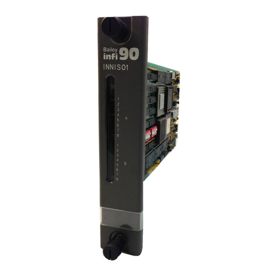
OPERATING PROCEDURES ® INNIS01 GROUP A LEDS GROUP B LEDS T00270A Figure 4-1. INNIS01 Module Faceplate LEDs INNPM11 NETWORK PROCESSING MODULE LEDs AND CONTROLS The faceplate of the INNPM11 module has the following compo- nents (refer to Figure 4-2): Status LED. •... -
Page 37: Innpm11 Modes Of Operation
OPERATING PROCEDURES IN N P M 1 1 R E D /G R E E N S TAT U S LE D LE D S 1 -8 S TO P /R E S E T P U S H B U T TO N T 00 32 9 A Figure 4-2. -
Page 38: Execute Mode
OPERATING PROCEDURES ® Execute Mode Execute mode is the normal mode of operation. In this mode, the INFI-NET system and modules in the process control unit interact through the process control unit interface. The NPM module can request exception reports, collect exception reports, allow the operator to adjust tunable module specifica- tions, and configure modules within a node residing on the INFI-NET system. -
Page 39: Section 5 - Troubleshooting
SECTION 5 - TROUBLESHOOTING INTRODUCTION Troubleshooting the process control unit interface is limited to viewing the contents of the error counters and the module sta- tus report from any INFI 90 OPEN operator interface. Refer to the instruction for your specific computer interface for infor- mation on module status reports. -
Page 40: Innpm11 Module Error Codes
TROUBLESHOOTING ® INNPM11 MODULE ERROR CODES If errors occur while the NPM module is operating, the status LED turns red and the CPU LEDs on the NPM module faceplate display error codes. Table lists the NPM module error codes and associated corrective action. The NPM module displays error codes only when it is halted. -
Page 41: Innis01 Module Edge Connectors
TROUBLESHOOTING A code that is not on the list may appear if a machine fault time-out occurs. Reset the NPM module if this happens. The NPM module has failed if the status LED remains red. Replace the NPM module in this case. INNIS01 MODULE EDGE CONNECTORS Tables through... -
Page 42: Innpm11 Module Edge Connectors
TROUBLESHOOTING ® Table 5-5. INNIS01 Module Edge Connector P3 Pin Assignments Signal Signal Receive 1 + Receive 1 - Ground Ground Ground Ground Bypass control + Bypass control - Ground Ground Transmit 1 + (phase 2) Transmit 1 - (phase 2) Transmit 1 - (phase 1) Transmit 1 + (phase 1) Ground... -
Page 43: Innpm11 Module Edge Connector P2 Pin Assignments
TROUBLESHOOTING Table 5-7. INNPM11 Module Edge Connector P2 Pin Assignments Signal Signal Data bit D1 Data bit D0 Data bit D3 Data bit D2 Data bit D5 Data bit D4 Data bit 7 Data bit D6 Clock Sync Unused Unused Table 5-8. -
Page 44: Section 6 - Maintenance
The reliability of any stand-alone product or control system is affected by the maintenance of the equipment. Elsag Bailey recommends that all equipment users practice a preventive maintenance program that will keep the equipment operating at an optimum level. -
Page 45: Equipment/Tools Required
MAINTENANCE ® Table 6-1. Preventitive Maintenance Schedule Task Frequency Check cabinet air filters. Clean or replace them as necessary. Check the air filter 3 months more frequently in excessively dirty environments. Check cabinet and process control unit interface modules for dust. Clean as necessary using an antistatic vacuum. -
Page 46: General Cleaning And Washing
MAINTENANCE GENERAL CLEANING AND WASHING If the printed circuit board needs minor cleaning, remove dust and residue from the printed circuit board surface using clean, dry, filtered compressed air or an antistatic field service vac- uum cleaner. Another method of washing the printed circuit board is: 1. -
Page 47: Checking Connections
MAINTENANCE ® Checking Connections Check all signal wiring, power and ground connections within the cabinet to verify their integrity. When checking connec- tions, always turn a screw, nut or other fastening device in the direction to tighten only. If the connection is loose, it will be tightened. -
Page 48: Section 7 - Repair/Replacement Procedures
SECTION 7 - REPAIR/REPLACEMENT PROCEDURES INTRODUCTION Repair procedures are limited to module replacement. If an INNIS01 or INNPM11 module fails, remove and replace it with another. Verify that the replacement module dipswitch and jumper settings are the same as those of the failed module. NOTE: Do not remove interface modules under power unless mod- ule operation has been halted. -
Page 49: Section 8 - Support Services
SECTION 8 - SUPPORT SERVICES INTRODUCTION Bailey Controls Company is ready to help in the use and repair of its products. Contact the nearest sales office to make requests for sales, applications, installation, repair, overhaul and maintenance contract services. REPLACEMENT PARTS AND ORDERING INFORMATION When making repairs, order replacement parts from a Bailey Controls Company sales office. -
Page 50: Appendix A - Ntcl01 Termination Unit Configuration
APPENDIX A - NTCL01 TERMINATION UNIT CONFIGURATION INTRODUCTION The INNIS01 Network Interface Slave Module (NIS) can use the NTCL01 Communication Termination Unit (TCL) for termina- tion. Jumpers on the TCL unit select the type of cable used to connect the NIS module to an INFI-NET system. Refer to the NTCL01 instruction for complete information. - Page 51 NTCL01 TERMINATION UNIT CONFIGURATION ® L O O P 2 N TC L 0 1 T B 2 N K L S0 1 8 7 6 5 4 3 2 1 N K L S1 1 IN N IS 0 1 8 7 6 5 4 3 2 1 T B 1 C O M...
-
Page 52: Redundant Process Control Unit Interface Ntcl01 Connections
NTCL01 TERMINATION UNIT CONFIGURATION L O O P 2 N TC L 01 T B 2 N K LS 01 /1 1 8 7 6 5 4 3 2 1 L O O P W IR IN G P R IM ARY IN N IS 0 1 8 7 6 5 4 3 2 1 T B 1... -
Page 53: Appendix B - Nicl01 Termination Module Configuration
APPENDIX B - NICL01 TERMINATION MODULE CONFIGURATION INTRODUCTION The INNIS01 Network Interface Slave Module (NIS) can use the NICL01 Communication Termination Module (ICL) for termina- tion. Jumpers on the ICL module select the type of cable used to connect the NIS module to an INFI-NET system. Refer to the NICL01 instruction for complete information. - Page 54 NICL01 TERMINATION MODULE CONFIGURATION ® N IC L 0 1 N K TL 0 1 -3 LOO P1 N K L S0 1 /1 1 O UT IN N IS 0 1 O UT LOO P2 N K C L 0 1 /1 1 N IC L 0 1 N K TL 0 1 -3 LOO P1...
-
Page 55: Redundant Process Control Unit Interface Nicl01 Connections
NICL01 TERMINATION MODULE CONFIGURATION N IC L0 1 LOO P 1 N K L S0 1/1 1 L O O P W IR IN G P R IM A RY IN N IS 01 LOO P 2 E XPA N D E R BU S P R IM A RY IN N P M ? 1... -
Page 56: Appendix C - Warm Failover Feature
APPENDIX C - WARM FAILOVER FEATURE INTRODUCTION The warm failover feature was developed for the process con- trol unit interface to minimize the interruption in the flow of exception reports that occurs when the backup process control unit interface re-establishes exception report routes once it becomes the primary process control unit interface. - Page 57 WARM FAILOVER FEATURE ® into its node without taking time to re-establish exception report routes. The backup NPM module must receive a copy of the primary NPM module database (not exception report data) over the NKMP01 or NKMP11 cable, before it is ready for warm failover. The database in the primary NPM module must be stable for 15 seconds before it can be transferred to the backup NPM mod- ule.
- Page 58 WARM FAILOVER FEATURE of exception reports, and for the backup NPM module to assume control. All test configurations are balanced in that both nodes import and export the same numbers and types of exception reports. Local time values represent the time required by the backup NPM module in a redundant interface node to recognize a primary NPM module failure, receive the indicated number of exception reports from and send the indi-...
- Page 59 Index Termination device NICL01 ............B-1 Abbreviations.............. 1-5 NTCL01 ............A-1 INNPM01 Configuration............3-8 Description .............1-2, 2-4 Configuration Edge connectors ...........5-4 INNIS01 ..............3-2 Error codes............5-2 NICL01............B-1 Installation ............3-12 NTCL01............A-1 LEDs and controls..........4-2 INNIS01NICL01 ............ B-1 Operating modes...........4-3 INNIS01NTCL01........... A-1 Replacement procedures ........7-1 INNPM01 ..............
- Page 60 ® Index (continued) PCU interface description ...........1-1 Termination devices NICL01..............B-1 NTCL01 ..............A-1 Terms ................. 1-5 Reference documents ..........1-5 Training............... 8-1 Replacement Troubleshooting............5-1 Parts ..............8-1 Procedures ............7-1 Unpacking and inspection .......... 3-2 User qualifications ............1-1 Special handling precautions ........3-1 Specifications ..............1-6 Warm failover .............C-1 Index - 2...
- Page 61 Telefax 39-10-6582-941 Telephone 49-69-799-0 Telefax 65-292-9011 Telefax 49-69-799-2406 Form WBPEEUI250016A1 Litho in U.S.A. 897 Copyright © 1997 by Elsag Bailey Process Automation, As An Unpublished Work ® Registered Trademark of Elsag Bailey Process Automation ™ Trademark of Elsag Bailey Process Automation...