
Subscribe to Our Youtube Channel
Related Manuals for Bailey Infi 90 INIIR01


Summary of Contents for Bailey Infi 90 INIIR01
- Page 1 E96-607 ® ® INFI-NET to INFI-NET Interface Modules Process Control and Automation Solutions from Elsag Bailey Group...
- Page 2 The information contained in this document is subject to change without notice. Elsag Bailey, its affiliates, employees, and agents, and the authors and contributors to this publication specif- ically disclaim all liabilities and warranties, express and implied (including warranties of merchantability and...
- Page 3 This instruction explains INFI-NET to INFI-NET interface mod- ule features, specifications and operation. It includes installa- tion, troubleshooting, maintenance and replacement procedures for each module. ® INFI-NET is a registered trademark of Elsag Bailey Process Automation. I-E96-607A...
- Page 4 ® List of Effective Pages Total number of pages in this instruction is 92, consisting of the following: Page No. Change Date Preface Original List of Effective Pages Original iii through ix Original 1-1 through 1-9 Original 2-1 through 2-7 Original 3-1 through 3-25 Original...
- Page 5 ® Safety Summary GENERAL Equipment Environment WARNINGS All components whether in transportation, operation or storage, must be in a noncorrosive environment. Electrical Shock Hazard During Maintenance Disconnect power or take precautions to insure that contact with energized parts is avoided when servicing. Special Handling This module uses electrostatic sensitive devices.
- Page 6 Sommaire de Sécurité AVERTISSEMENT Environment de l'équipement D'ORDRE Nes pas soumettre les composantes à une atmosphère corrosive GENERAL lors du transport, de l'entreposage ou de l'utilisation. Risques de chocs electriques lor de l'entretien S'assurer de débrancher l'alimentation ou de prende les précau- tions nécessaires a éviter tout contact avec des composants sours tension lors de l'entretien.
-
Page 7: Table Of Contents
Table of Contents Page SECTION 1 - INTRODUCTION ....................1-1 INTRODUCTION......................1-1 INTENDED USER ......................1-1 INTERFACE DESCRIPTION ..................1-1 INFI-NET to INFI-NET Remote Interface ..............1-1 INFI-NET to INFI-NET Local Interface ..............1-3 MODULE DESCRIPTION ....................1-4 Network Interface Slave Module ................1-4 INIIT02 INFI-NET to INFI-NET Transfer Module ............1-4 INIIT03 INFI-NET to INFI-NET Transfer Module ............1-5 FEATURES........................1-5 INSTRUCTION CONTENT .....................1-6... - Page 8 ® Table of Contents (continued) Page SECTION 3 - INSTALLATION (continued) UNPACKING AND INSPECTION..................3-2 INIIR01 INFI-NET TO INFI-NET REMOTE INTERFACE INSTALLATION ......3-2 Termination Unit/Module Configuration and Installation ........3-3 NTCL01 or NICL01 Installation ................ 3-3 NTMP01 or NIMP01 Installation ..............3-3 INNIS01 Module Dipswitches .................
- Page 9 Table of Contents (continued) Page SECTION 4 - OPERATING PROCEDURES (continued) INIIT03 INFI-NET TO INFI-NET TRANSFER MODULE LEDs AND CONTROLS ....4-6 Red/Green Status LED ..................4-6 Bank A CPU LEDs ....................4-6 Stop/Reset Switch ....................4-8 INIIL02 MODE OF OPERATION ..................4-8 INTERFACE POINT CAPACITY ..................4-8 SECTION 5 - TROUBLESHOOTING ...................5-1 INTRODUCTION......................5-1 INNIS01 ERROR CODES ....................5-1...
- Page 10 ® Table of Contents (continued) Page APPENDIX E - INIIR01 REDUNDANT CONFIGURATIONS............E-1 INTRODUCTION ......................E-1 REDUNDANT CONFIGURATIONS ................E-1 Switch Settings for Redundancy ................E-1 Redundant Hardware Configuration Example ............E-1 Redundant Termination Units/Modules..............E-2 List of Figures Title Page 1-1. INFI-NET to INFI-NET Remote Interface ..............1-2 1-2.
- Page 11 List of Tables Title Page 1-1. Reference Documents ....................1-7 1-2. Nomenclature ......................1-7 1-3. Glossary of Terms and Abbreviations ..............1-8 1-4. Specifications......................1-9 3-1. INNIS01 Dipswitch SW1/SW2, Node Address/Loop Address Example Settings ..3-5 3-2. INNIS01 Dipswitch SW3, Loop Mode ..............3-5 3-3. INNIS01 Dipswitch SW4, I/O Expander Bus Address Example Settings ....3-6 3-4.
-
Page 12: Section 1 - Introduction
INIIT02 module are determined by specifications in the INIIT02 executive block (function code 202). These specifica- tions are configurable to fit the needs of the application. ® INFI 90 is a registered trademark of Elsag Bailey Process Automation. INTRODUCTION I-E96-607A... -
Page 13: Infi-Net To Infi-Net Remote Interface
INTRODUCTION ® CENTRAL INFI-NET LOOP 10 MBAUD 250 NODES NICL01 NTCL01 INNIS01 I/O EXPANDER BUS NTMP01 INIIT02 NIMP01 CONTROLWAY/MODULE BUS RS-232-C VIA TRANSCEIVER MODEM SATELLITE CONTROLWAY/MODULE BUS LINK NTMP01 INIIT02 NIMP01 I/O EXPANDER BUS INNIS01 NICL01 NTCL01 SATELLITE INFI-NET LOOP 10 MBAUD 250 NODES T00193A... -
Page 14: Infi-Net To Infi-Net Local Interface
INTRODUCTION INFI-NET to INFI-NET Local Interface The INIIL02 INFI-NET to INFI-NET Local Interface is made up of two NIS modules and the INIIT03 INFI-NET to INFI-NET Trans- fer Module. This interface provides a communication path between a cen- tral INFI-NET loop and a local satellite INFI-NET loop (Figure 1-2). -
Page 15: Module Description
INTRODUCTION ® on the two communication loops is 45.8 meters (150 feet). Bidi- rectional communication from the central communication loop is through cable connection to the NTCL01 Communication Termination Unit or NICL01 Communication Termination Mod- ule. This interface transfers system data, control and configuration messages, and exception reports between two INFI-NET com- munication networks. -
Page 16: Iniit03 Infi-Net To Infi-Net Transfer Module
INTRODUCTION module. The circuit board contains the serial communication circuitry necessary for it to communicate with another INIIT02 module. Two captive latches on the INIIT02 faceplate secure the module in the MMU card cage. The faceplate contains eight CPU LEDs, a red/green status LED, and a stop/reset switch. -
Page 17: Instruction Content
INTRODUCTION ® INSTRUCTION CONTENT This manual provides introductory, installation, operation, troubleshooting and maintenance information. Read and understand this document before placing the communication system into service. Introduction Provides an overview of the interfaces and modules, description of hardware, glossary of unique terms, reference documenta- tion, and physical and electrical specifications. -
Page 18: Reference Documents
INTRODUCTION 5. Read Section 7 if system repair or replacement is needed. 6. Refer to Section 8 for ordering information, training and documentation. REFERENCE DOCUMENTS Table lists documents with additional information that is related to the INFI-NET to INFI-NET interfaces. Table 1-1. -
Page 19: Glossary Of Terms And Abbreviations
Provides input/output connection between plant equipment and the INFI 90/ Network 90 modules. Termination Unit Provides input/output connection between plant equipment and the INFI 90/ Network 90 modules. ® Network 90 is a registered trademark of Elsag Bailey Process Automation. GLOSSARY OF TERMS AND ABBREVIATIONS 1 - 8 I-E96-607A... -
Page 20: Specifications
INTRODUCTION SPECIFICATIONS Table contains INFI-NET to INFI-NET interface module specifications. Table 1-4. Specifications Property Characteristic/Value INNIS01 module Power requirements Voltage (VDC) Current (mA) Power (W) + 15 0.075 – 15 128 kbytes processor RAM Memory 80 kbytes other RAM 64 kbytes processor ROM 2 Mbaud or 10 Mbaud Communication rates 62,500 system nodes, 250 nodes per loop... -
Page 21: Section 2 - Description And Operation
SECTION 2 - DESCRIPTION AND OPERATION INTRODUCTION INFI-NET is a unidirectional, high-speed serial data highway that all INFI 90 nodes share. The INNIS01 Network Interface Slave Module and the INIIT02 INFI-NET to INFI-NET Transfer Module make up an INIIR01 INFI-NET to INFI-NET Remote Interface. -
Page 22: Time Synchronization
DESCRIPTION AND OPERATION ® TIME SYNCHRONIZATION The time synchronization message is a high priority broadcast type of message. The NIS module services this message type immediately. Time synchronization provides a common system time base for sequencing exception reports, and accessing trend data for display on a system console. -
Page 23: Nis Module Data Integrity
DESCRIPTION AND OPERATION NIS MODULE DATA INTEGRITY Retry Logic If, on the first message transmission, the NIS module does not receive an acknowledge (ACK) or busy negative acknowledge (NAK) from the destination node, it transmits the message again up to 11 times. If, after this series of retries, there is still no response, the destination node is marked off-line and the NIS module informs the transfer module of the negative acknowledge. -
Page 24: Exception Reporting
DESCRIPTION AND OPERATION ® Exception Reporting The INIIT02 module maintains a database of all points that send or receive exception reports to or from the remote loop. The INIIT02 database contains specifications for each point that helps the INIIT02 module sort and package requests from other points more efficiently. -
Page 25: Framing
DESCRIPTION AND OPERATION recovery. The INFI 90 application layers in both the central and satellite loop INIIT02 modules use the link control layer to transport control and configuration information and exception reports. Framing The INIIT02 module uses message framing to help it track data bytes that pass through the asynchronous communication link. -
Page 26: Start-Up Control
DESCRIPTION AND OPERATION ® Start-Up Control If either INIIT02 module is restarted, it sends a message to the other INIIT02 module so that it can take the steps needed to synchronize itself with the restarted transfer module. Redundancy Redundancy requires a full set of duplicate modules (two INNIS01 modules and two INIIT02 modules on each loop). -
Page 27: Redundancy
DESCRIPTION AND OPERATION respond as node off-line (NOL). Some messages, such as con- trol and configuration messages, pass through the INIIT03 module unchanged and the original source of the message is responsible for retrying them. The local interface notifies the message source node when there is a destination node off-line. -
Page 28: Section 3 - Installation
Follow these han- dling procedures: NOTE: Always use Bailey's field static kit (part number 1948385_1 - consisting of two wrist straps, ground cord assembly, alligator clip, and static dissipative work surface) when working with the modules. -
Page 29: Unpacking And Inspection
UNPACKING AND INSPECTION 1. Examine the hardware immediately to verify that it has not been damaged in transit. 2. Notify the nearest Bailey Controls Company sales office of any such damage. 3. File a claim for any damage with the transportation com- pany that handled the shipment. -
Page 30: Termination Unit/Module Configuration And Installation
INSTALLATION external serial communication link. Refer to Appendix E more information on how to set up redundant remote interfaces. To install an INFI-NET to INFI-NET remote interface: 1. Set the jumpers on all the termination units or modules. 2. Install all the termination units or modules and their cables. 3. -
Page 31: Innis01 Module Dipswitches
INSTALLATION ® Multi-Function Processor Termination Unit (NTMP01) instruction or the Multi-Function Processor Termination Mod- ule (NIMP01/02) instruction for specific directions on configur- ing jumpers, mounting, termination cable installation, and RS-232-C cable lengths. INNIS01 Module Dipswitches Each INFI-NET to INFI-NET interface requires two INNIS01 Network Interface Slave Modules. -
Page 32: Innis01 Dipswitch Sw3, Loop Mode
Table 3-2). Set pole one to the one position for all INFI-NET to INFI-NET interfaces. Pole two enables or disables ROM check- summing. Bailey recommends that the NIS module be installed with checksumming enabled to take full advantage of the on-board diagnostics. -
Page 33: Innis01 Dipswitch Sw4, Event And Error Counters
INSTALLATION ® Table 3-2. INNIS01 Dipswitch SW3, Loop Mode (continued) Pole User Function 1 2 3 4 5 6 7 8 Setting Toggle group A LEDs if loop 1 is idle or shorted. Toggle group B LEDs if loop 2 is idle or shorted. LED display defined by SW4. -
Page 34: Innis01 Dipswitch Sw4, Event Counter Address
INSTALLATION Table 3-4. INNIS01 Dipswitch SW4, Event Counter Address Pole User Description Setting Number of timer interrupts. Number of multicast messages received, excluding origi- nated messages. Number of multicast destinations received. Number of time sync messages received, excluding origi- nated messages. Number of broadcast messages received, excluding origi- nated messages. -
Page 35: User-Configured Jumpers
INSTALLATION ® Table 3-5. INNIS01 Dipswitch SW4, Error Counter Address Pole User Description Setting Number of channel 1 receive errors. Number of channel 2 receive errors. Number of transmitter errors. Number of receive queue overflow errors. Number of messages dumped with circulation count errors. Number of messages dumped with message type or desti- nation count errors. -
Page 36: Iniit02 Module Dipswitches
INSTALLATION This signal is fed through the termination unit cable to the P3 connector on the NIS module. The power system status input is a TTL-compatible signal. A five-VDC signal (logic high) on power system status indicates good status; a zero-VDC signal (logic low) indicates bad status. -
Page 37: Iniit02 Module Circuit Board Layout
INSTALLATION ® -30 VDC SYSTEM (DEFAULT) CONTROLWAY MACHINE FAULT TIMER JUMPER POSTS 1 2 3 4 5 6 7 8 1 2 3 4 5 6 7 8 JUMPERS AND POSTS T00197A Figure 3-3. INIIT02 Module Circuit Board Layout Table 3-6. INIIT02 Dipswitch SW3, Test/Module Address Pole User Function... -
Page 38: Iniir01 Interface Mounting Unit Preparation
INSTALLATION Table 3-7. INIIT02 Dipswitch SW4, Options Pole User Function 1 2 3 4 5 6 7 8 Setting ROM checksum enabled. ROM checksum disabled. RS-232-C DTE mode (direct connections). RS-232-C DCE mode (modem connections). Equipment select output initially de-energized. Equipment select output initially energized. -
Page 39: Checking The Module Mounting Unit For -30 Vdc
-30 VDC faston. 4. For additional information and/or assistance, contact Bailey Controls technical support. INIIT02 INSTALLATION OPTIONS There are two installation options available. The first option applies to systems that do not have -30 VDC power. The sec- ond option is for systems that have -30 VDC power. -
Page 40: Installing The Iniir01 Interface Modules
NOTE: The I/O expander bus for each set of one INNIS01 module and one INIIT02 module must be as short as possible. Bailey recom- mends that adjacent MMU slots be connected for each set of inter- face modules. Failure to keep the I/O expander bus short results in unreliable operation. -
Page 41: Example Of How To Isolate A Module Mounting Unit
INSTALLATION ® REMOVE DIPSHUNT TO ISOLATE I/O EXPANDER BUS REMOVE DIPSHUNT TO OF REDUNDANT INTERFACE ISOLATE I/O EXPANDER (FRONT OF MMU) BUS (FRONT OF MMU) EACH BRACKET RIBBON CABLE INSTALLED REMOVE RIBBON CABLE CONTAINS AN ISOLATED HERE PROVIDES TO ISOLATE I/O EXPANDER I/O EXPANDER BUS ADDITIONAL SLOTS FOR BUS FROM MMU BELOW... -
Page 42: Typical Iniir01 Module Slot Assignment In The Module Mounting Unit
INSTALLATION To install the INIIT02 and INNIS01 modules: 1. There must be 2 empty slots (side by side) available in one module mounting unit (on each loop) to install one interface. Redundant interfaces require 4 slots or more depending on the application (see Figure 3-5). -
Page 43: Iniit02 Executive Block Initialization
INSTALLATION ® 3. Verify that there are no other modules on the I/O expander bus of each INIIT02/INNIS01 pair. 4. Mount each module in its assigned MMU slot one at a time. 5. Guide the top and bottom edges of each circuit card along the top and bottom rails of its MMU slot. -
Page 44: Iniil02 Infi-Net To Infi-Net Local Interface Installation
INSTALLATION Table 3-8. Optional Digital I/O Modules Nomenclature Output Document No. IMDSM05 24 VDC I-E96-309 IMDSO01 24 to 240 VAC I-E96-310 IMDSO02 4 to 50 VDC IMDSO03 5 to 160 VDC IMDSO04 24 VDC I-E96-313 INIIL02 INFI-NET TO INFI-NET LOCAL INTERFACE INSTALLATION Install the modules and termination devices and cables that make up an INIIL02 INFI-NET to INFI-NET Local Interface. -
Page 45: Ntcl01 Or Nicl01 Installation
INSTALLATION ® NTCL01 or NICL01 Installation Configure and install the required termination units or modules and their cables before installing any of the interface modules. The INNIS01 module terminates through an NTCL01 Commu- nication Termination Unit or an NICL01 Communication Ter- mination Module. -
Page 46: Iniit03 Dipswitch Umb1, Module Options And Diagnostics
INSTALLATION MODB CR17 BAUD OPTION RATE DIAGNOSTICS SCSI SWITCH SWITCH SWITCH SWITCH 2MBIT 4MBIT 1MBIT 1 2 3 4 5 6 7 8 1 2 3 4 5 6 7 8 1 2 3 4 5 6 7 8 1 2 3 4 5 6 7 8 OPEN OPEN... -
Page 47: Iniit03 Dipswitch Llb3, Diagnostics
NOTE:0 = CLOSED or ON, 1 = OPEN or OFF. INIIT03 DIPSWITCH LLB3, DIAGNOSTICS Dipswitch LLB3 selects certain operating options and enables diagnostics that are meaningful to qualified Bailey Controls Company service personnel. All switch positions on LLB3 should be set as shown for normal operation. - Page 48 INSTALLATION Table 3-11. INIIT03 Dipswitch LLB3, Diagnostics (continued) Pole User Function 1 2 3 4 5 6 7 8 Setting INFI-NET diagnostic utilities disabled. INFI-NET diagnostic utilities enabled. Common time synchronization between loops. Time synchronization isolation. Not used. Must be set as shown. Not used.
-
Page 49: Hw Setup Dipshunt
Connects Controlway channel B for operation in module mounting units that have Controlway (INFI 90). NOTES: 1.This feature is used by Bailey service personnel. The J1 setting does not affect the module during normal operation. 2.Refer to INIIT03 INSTALLATION OPTIONS for an explanation of the installation options available when installing the INIIL02 interface in a system that uses -30 VDC. -
Page 50: Checking The Module Mounting Unit For -30 Vdc
Remove -30 VDC from the module mounting unit by removing the supply wiring from the -30 VDC faston. 4. For additional information and/or assistance, contact Bailey Controls technical support. INIIT03 INSTALLATION OPTIONS There are two installation options available. The first option applies to systems that do not have -30 VDC power. -
Page 51: Installing The Interface Modules
NOTE: The I/O expander bus for each set of two INNIS01 modules and one INIIT03 module must be as short as possible. Bailey recom- mends that three adjacent MMU slots be connected for each set of interface modules. Failure to keep the I/O expander bus short results in unreliable operation. -
Page 52: Typical Iniil02 Module Slot Assignment In The Module Mounting Unit
INSTALLATION To install the INIIT03 and INNIS01 modules: 1. There must be 3 empty slots (side by side, see Figure 3-7) available in 1 MMU card cage to install 1 interface (6 slots for a redundant interface). 2. Verify that there are 24-pin dipshunts installed in the I/O expander bus sockets between the MMU slots to be used by both NIS modules and the slot to be used by the INIIT03 mod- ule. -
Page 53: Section 4 - Operating Procedures
SECTION 4 - OPERATING PROCEDURES INTRODUCTION After completing the procedures in Section 3, the INFI-NET to INFI-NET communication interfaces are ready to be put into operation. This section explains information for daily operation of these interfaces. INNIS01 MODULE START-UP PROCEDURES On power up, the network interface slave (NIS) module micro- processor stays in reset until its associated transfer module (INIIT02 or INIIT03 module) removes the reset and allows the... -
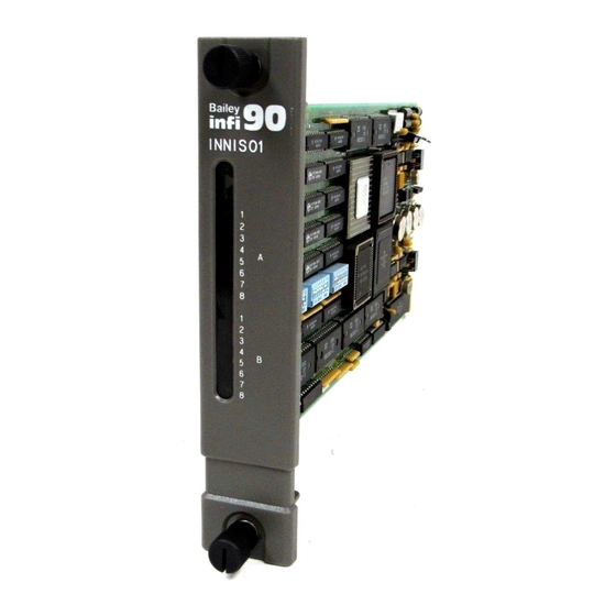
Page 54: Iniit02 Module Leds And Controls
OPERATING PROCEDURES ® INNIS01 GROUP A CPU LEDS GROUP B CPU LEDS T00202A Figure 4-1. INNIS01 Faceplate INIIT02 MODULE LEDs AND CONTROLS The faceplate of the INIIT02 module has the following compo- nents (see Figure 4-2): 1. One red/green status LED. 2. -
Page 55: Iniit02 Faceplate
OPERATING PROCEDURES INIIT02 RED/GREEN STATUS LED CPU LEDS STOP/RESET SWITCH T00203A Figure 4-2. INIIT02 Faceplate Table 4-1. INIIT02 Red/Green Status LED States LED State Meaning No power to the IIT module or the machine fault timer is disabled (jumper installed) and the module is running. Solid green The IIT module is in execute mode. -
Page 56: Stop/Reset Switch
OPERATING PROCEDURES ® Stop/Reset Switch Push the stop pushbutton once and wait for the red/green sta- tus LED to turn red before removing the INIIT02 module from the module mounting unit. Using the stop pushbutton allows any NVRAM write in progress to complete before the module halts operation. -
Page 57: Determining Iniit02 Module Point Count
OPERATING PROCEDURES Use CAD/TXT release 4.2.3 or higher to configure the INIIT02 executive block (FC 202). The executive block of the INIIT02 module can also be configured using a configuration tuning module (CTM). To use a CTM module, the INIIT02 module is set to module bus (83.3 kilobaud) (dipswitch SW3 pole three, refer to Table 3-6) and the CTM module addresses the module at its module bus address (dipswitch SW3 pole eight, refer to Table... -
Page 58: Bytes Required For Block Type
OPERATING PROCEDURES ® Table 4-4. Bytes Required for Block Type Bytes Block Type Block Status Value Specs Total Digital — — Module status — — Extended module status — — Analog real-3 RMSC real-3 Analog real-4 RMSC real-4 Station real-3 DAANG real-3 Station real-4 DAANG real-4... -
Page 59: Iniit03 Infi-Net To Infi-Net Transfer Module Leds And Controls
OPERATING PROCEDURES INIIT03 RED/GREEN STATUS LED BANK A CPU LEDS BANK B CPU LEDS STOP/RESET SWITCH T00204A Figure 4-3. INIIT03 Faceplate Table 4-5. INIIT03 Red/Green Status LED States LED State Meaning No power to the IIT module or the machine fault timer is disabled (jumper installed) and the module is running. -
Page 60: Stop/Reset Switch
OPERATING PROCEDURES ® Stop/Reset Switch Push the stop/reset switch once and wait for the status LED to turn red before removing the INIIT03 module from the module mounting unit. After the module is stopped, pushing the stop/reset switch resets the INIIT03 module. This action: 1. -
Page 61: Iniil02 Memory Usage By Tag, Point And Record Type
OPERATING PROCEDURES Table 4-8. INIIL02 Memory Usage by Tag, Point and Record Type Memory Bytes Tag Type (Acronym) Point Type Record Type Required Digital (DIGITAL) Digital Plant loop analog (ANALOG) Analog real 3 INFI-NET analog (ANALOG) Analog real 4 Multi-state device driver (MSDD) Remote switch Device driver (DD) Remote switch... -
Page 62: Section 5 - Troubleshooting
SECTION 5 - TROUBLESHOOTING INTRODUCTION Troubleshooting the INFI-NET interface modules is limited to viewing the contents of the error counters (CPU LEDs) and the module status report from any INFI 90 operator interface. Refer to the product instruction for your specific interface for infor- mation on accessing module status reports. -
Page 63: Iniit02 Error Codes
TROUBLESHOOTING ® INIIT02 ERROR CODES If module errors occur while the INIIT02 INFI-NET to INFI-NET Transfer Module is operating, the module halts, the status LED turns red, and the eight CPU LEDs display an error code. Table lists the INIIT02 error codes, their meaning and corrective action. -
Page 64: Iniit02 Module Status Summary
ASCII tags, incomplete console data- bases, or missing XR source nodes. If error continues contact Bailey technical support. 0 0 1 1 0 0 0 1 Memory or CPU fault. Replace INIIT03. 0 0 1 1 0 0 1 0 Address or bus error. -
Page 65: Iniit03 Module Status Summary
TROUBLESHOOTING ® Table 5-3. INIIT03 Module Error Codes (continued) Bank B CPU LEDs Code Error Condition Corrective Action 8 7 6 5 4 3 2 1 0 0 1 1 0 0 1 1 Illegal instruction. Reset INIIT03; replace if error con- tinues. -
Page 66: Innis01 Edge Connector P1 Pin Assignments
TROUBLESHOOTING Table 5-4. INNIS01 Edge Connector P1 Pin Assignments Signal Signal +5 VDC +5 VDC Unused Unused Common Common +15 VDC -15 VDC Power fail interrupt Power fail interrupt Unused Unused NOTE: 1.Active low. Table 5-5. INNIS01 Edge Connector P2 Pin Assignments Signal Signal Addr. -
Page 67: Iniit02 Edge Connector P1 Pin Assignments
TROUBLESHOOTING ® Table 5-7. INIIT02 Edge Connector P1 Pin Assignments Signal Signal +5 VDC +5 VDC No connection Controlway Common Common Not used Not used Power fail interrupt Power fail interrupt Controlway 1 No connection NOTE: 1.Active low. Table 5-8. INIIT02 Edge Connector P2 Pin Assignments Signal Signal Data bit D1... -
Page 68: Iniit03 Edge Connector P1 Pin Assignments
TROUBLESHOOTING Table 5-10. INIIT03 Edge Connector P1 Pin Assignments Signal Signal +5 VDC +5 VDC No connection Controlway B/NC Common Common No connection Not used Power fail interrupt No connection Controlway A / module bus No connection NOTE: 1.Active low. Table 5-11. - Page 69 TROUBLESHOOTING ® Table 5-13. RS-232-C Diagnostic Port P4 Pin Assignment Signal P4 Configured P4 Configured as DCE as DTE NOTE: This terminal is useful only to qualified Bailey per- sonnel. EDGE CONNECTOR PIN ASSIGNMENTS 5 - 8 I-E96-607A...
-
Page 70: Section 6 - Maintenance
The reliability of any stand alone product or control system is affected by the maintenance of the equipment. Bailey Controls Company recommends that all equipment users practice a pre- ventive maintenance program that will keep the equipment operating at an optimum level. -
Page 71: Preventive Maintenance Schedule
MAINTENANCE ® PREVENTIVE MAINTENANCE SCHEDULE Table is the preventive maintenance schedule for the INFI-NET to INFI-NET interface modules. The table lists the preventive maintenance tasks in groups according to their specified maintenance interval. Some tasks in Table self explanatory. Instruction for tasks that require further PREVENTIVE MAINTENANCE explanation are covered under PROCEDURES. -
Page 72: Preventive Maintenance Procedures
MAINTENANCE PREVENTIVE MAINTENANCE PROCEDURES This section covers tasks from Table that require specific instructions or further explanation: Checking signal, power and ground connections. • Cleaning printed circuit boards and edge connectors. • Checking Connections Check all signal wiring, power and ground connections to the interface modules and their associated termination unit or module. -
Page 73: Edge Connector Cleaning
MAINTENANCE ® EDGE CONNECTOR CLEANING To clean edge connector contacts: 1. Use a solvent mixture of 80% isopropyl alcohol (99.5% elec- tronic grade) and 20% distilled water. 2. Soak a lint free cloth with the solvent mixture. 3. Work the cloth back and forth parallel to the edge connec- tor contacts. -
Page 74: Section 7 - Repair/Replacement Procedures
There are no special tools required to replace any of the INFI-NET to INFI-NET interface modules. NOTE: Always use the Bailey field static kit (part number 1948385_1) when working with any INFI-NET interface module. This kit connects the static dissipative work surface and technician to the same ground point. -
Page 75: Section 8 - Support Services
SECTION 8 - SUPPORT SERVICES INTRODUCTION Bailey Controls Company is ready to help in the use and repair of its products. Contact the nearest sales office to make requests for sales, applications, installation, repair, overhaul and maintenance contract services. REPLACEMENT PARTS AND ORDERING INFORMATION When making repairs at your facility, order replacement parts from a Bailey Controls Company sales office. -
Page 76: Appendix A - Ntcl01 Termination Unit Configuration
APPENDIX A - NTCL01 TERMINATION UNIT CONFIGURATION INTRODUCTION The INNIS01 Network Interface Slave Module terminates through an NTCL01 Communication Termination Unit via a cable connection (NKLS01 or NKLS11 termination cable). Twi- nax or coax cable may be used to connect the interface to the communication loop. -
Page 77: Ntcl01 Termination Unit Cable Connections
NTCL01 TERMINATION UNIT CONFIGURATION ® Table A-1. NTCL01 Jumper Settings, Circuit Board Revisions D and E Jumper No. Twinax Coax J5 to J12 1 2 3 1 2 3 J13 to J18 1 2 3 1 2 3 T00206A Table A-2. NTCL01 Jumper Settings, Circuit Board Revision F and Higher Jumper No. -
Page 78: Appendix B - Nicl01 Termination Module Configuration
APPENDIX B - NICL01 TERMINATION MODULE CONFIGURATION INTRODUCTION The INNIS01 Network Interface Slave Module terminates through an NICL01 Communication Termination Module via a cable connection (NKLS02 or NKLS12 termination cable). Twi- nax or coax cable may be used to connect the interface to the communication loop. -
Page 79: Nicl01 Termination Module Cable Connections
NICL01 TERMINATION MODULE CONFIGURATION ® Table B-1. NICL01 Jumper Settings, Circuit Board Revision C Jumper No. Twinax Coax J5 to J12 1 2 3 1 2 3 J13 to J18 1 2 3 1 2 3 T00206A Table B-2. NICL01 Jumper Settings, Circuit Board Revisions D and Higher Jumper No. -
Page 80: Appendix C - Ntmp01 Termination Unit Configuration
APPENDIX C - NTMP01 TERMINATION UNIT CONFIGURATION INTRODUCTION The INIIT02 INFI-NET to INFI-NET Transfer Module uses the NTMP01 Multi-Function Processor Termination Unit for termi- nation. Figure shows the dipshunt configuration required for ports one or two to operate as a data port. Figure shows the dipshunt configuration required for port two to drive a diagnostic terminal. -
Page 81: Jumper Configuration For Diagnostic Port (Port 2 Only
NTMP01 TERMINATION UNIT CONFIGURATION ® J1 AND J2 DB25-3 TXD-A RXD-A DB25-2 RTS-A DB25-4 DB25-5 CTS-A T00210A Figure C-2. Jumper Configuration for Diagnostic Port (Port 2 Only) +12 V J6 AND J8 DB25-6 J5 AND J9 DB25-8 J7 AND J10 DB25-20 J4 AND J3 PROT-GND... -
Page 82: Jumper Settings For J14 Through J17
NTMP01 TERMINATION UNIT CONFIGURATION DIGIN 1 (+) CTSB (+) DIGIN 1 (-) CTSB (-) T00212A Figure C-4. Jumper Settings for J14 through J17 RXDA FROM CTSA PORT1 RXDA (–) J18 MUST BE INSTALLED RXDA (+) AS SHOWN RS-485 RECEIVER ENABLE T00049A Figure C-5. - Page 83 NTMP01 TERMINATION UNIT CONFIGURATION ® SECONDARY INIIT02 ACTIVE NTMP01 SECONDARY INIIT02 DATA PORT 1 +24 V RS-485 PORT SPARE CHASSIS DIGITAL GROUND INPUT FUSE F1 DIAGNOSTIC PORT 2 PRIMARY INIIT02 SPARE PRIMARY INIIT02 ACTIVE T00213A Figure C-6. NTMP01 Connector Assignments and Jumper Locations NTMP01 NKTU01/11 PORT 1...
-
Page 84: Appendix D - Nimp01 And Nimp02 Termination Module Configuration
APPENDIX D - NIMP01 AND NIMP02 TERMINATION MODULE CONFIGURATION INTRODUCTION The INIIT02 INFI-NET to INFI-NET Transfer Module can use the NIMP01 or NIMP02 Multi-Function Processor Termination Module for termination. The NIMP02 termination module is required only for redundant INFI-NET to INFI-NET interfaces. Figure shows the dipshunt configuration required for port one or two to operate as a data port. -
Page 85: Handshake Signal Schematic (Normally Installed
NIMP01 AND NIMP02 TERMINATION MODULE CONFIGURATION ® J1 AND J2 DB25-3 TXD-A RXD-A DB25-2 RTS-A DB25-4 DB25-5 CTS-A T00210A Figure D-2. Jumper Configuration for Diagnostic Port (Port 2 Only) +12V J6/J8 P5/6-6 J5/J9 P5/6-1 J7/10 P5/6-4 P5/6-5 T00054A Figure D-3. Handshake Signal Schematic (Normally Installed) INTRODUCTION D - 2... -
Page 86: Jumper Settings For J14 Through J17
NIMP01 AND NIMP02 TERMINATION MODULE CONFIGURATION DIGIN 1 (+) CTSB (+) DIGIN 1 (-) CTSB (-) T00212A Figure D-4. Jumper Settings for J14 through J17 RXDA FROM CTSA PORT1 RXDA (–) J18 MUST BE INSTALLED RXDA (+) AS SHOWN RS-485 RECEIVER ENABLE T00049A Figure D-5. - Page 87 NIMP01 AND NIMP02 TERMINATION MODULE CONFIGURATION ® CHASSIS GROUND SYSTEM COMMON +24 VDC DATA PORT 1 (RS-232-C) DIAGNOSTIC PORT 2 (RS-232-C) RS-485 PORT SPARE DIGITAL INPUT FUSE F1 T00215A Figure D-6. NIMP01 Connector Assignments and Jumper Locations NIMP01 PORT 1 NKTM01 PORT 2 NKTU02/12...
-
Page 88: Appendix E - Iniir01 Redundant Configurations
APPENDIX E - INIIR01 REDUNDANT CONFIGURATIONS INTRODUCTION This section provides information on various ways to terminate a redundant INIIR01 INFI-NET to INFI-NET Remote Interface. Redundant interfaces provide an additional level of operational security against module or communication system component failure. REDUNDANT CONFIGURATIONS Redundant INIIT02 INFI-NET to INFI-NET Transfer Modules must share a common Controlway or module bus. -
Page 89: Redundant Termination Units/Modules
INIIR01 REDUNDANT CONFIGURATIONS ® PRIMARY SECONDARY INIIT02 IMDMS05 INIIT02 IMDMS05 – – ANTENNA NKTU01 SELECT – SWITCH – NTDI01 NKTU01 PRIMARY ENABLE TRANSCEIVER NKTU01 – – NKTU01 – REDUNDANT ENABLE TRANSCEIVER – NTDI01 RS-232-C (LINES 1-5, 8, 20) NTMP01 MODEM T00217A Figure E-1. -
Page 90: Redundant Transfer Modules Using One Termination Unit
INIIR01 REDUNDANT CONFIGURATIONS NKTU01 INIIT02 NTMP01 MODULE BUS/CONTROLWAY CARRIES REDUNDANCY COMMUNICATION NKTU01 INIIT02 T00218A Figure E-2. Redundant Transfer Modules Using One Termination Unit tion unit and communicate through one or two serial channels. The primary INIIT02 module controls the termination unit. Figure shows redundant INIIT02 modules using NIMP01 and NIMP02 Multi-Function Processor Termination Modules. -
Page 91: Redundant Transfer Modules Using Nimp01 And Nimp02 Termination Modules
INIIR01 REDUNDANT CONFIGURATIONS ® NKMR02 (DB9 TO DB25) NKTU02 NIMP01 INIIT02 MODULE BUS/CONTROLWAY CARRIES REDUNDANCY COMMUNICATION 6634408A2 RIBBON CABLES NKTU02 NIMP02 INIIT02 T00219A Figure E-3. Redundant Transfer Modules Using NIMP01 and NIMP02 Termination Modules NKTU01 NTMP01 INIIT02 MODULE BUS/CONTROLWAY CARRIES REDUNDANCY COMMUNICATION NKTU01 NTMP01... -
Page 92: Redundant Transfer Modules With Redundant Nimp01 Termination Modules
INIIR01 REDUNDANT CONFIGURATIONS NKMR02 (DB9 TO DB25) NKTU02 INIIT02 NIMP01 MODULE BUS/CONTROLWAY CARRIES REDUNDANCY COMMUNICATION NKMR02 (DB9 TO DB25) NKTU02 NIMP01 INIIT02 T00221A Figure E-5. Redundant Transfer Modules with Redundant NIMP01 Termination Modules REDUNDANT CONFIGURATIONS I-E96-607A E - 5... - Page 93 Index Installation options ..........3-23 Jumpers ..............3-21 Document numbers ............ 1-7 Memory usage ............4-8 Documentation ............8-1 Module address...........3-18 Module status............5-4 Operation ..............4-6 Options and diagnostics......3-19, 3-20 Glossary ..............1-8 Status LED ............4-6 Status summary ............5-4 Stop/reset switch ...........4-8 INNIS01 module Handling precautions..........
- Page 94 ® Index (continued) Jumpers..............C-1 Redundant configuration ........E-2 Redundant hardware ..........E-1 Reference documents ..........1-7 Replacement procedures ........... 7-1 Ordering information ...........8-1 Specifications ............. 1-9 Power requirements ............1-9 Power system status ...........3-8 Preventive maintenance..........6-1 Training............... 8-1 Procedures ............6-3 Troubleshooting............5-1 Schedule ...............6-2 Index - 2 I-E96-607A...
- Page 95 ASIA/PACIFIC EUROPE, AFRICA, MIDDLE EAST Graefstrasse 97 Form I-E96-607A Litho in U.S.A. 294 Copyright © 1994 by Elsag Bailey Process Automation, As An Unpublished Work ® Registered Trademark of Elsag Bailey Process Automation ™ Trademark of Elsag Bailey Process Automation...
Need help?
Do you have a question about the Infi 90 INIIR01 and is the answer not in the manual?
Questions and answers