
Related Manuals for Bailey Infi 90 IMDSO04


Summary of Contents for Bailey Infi 90 IMDSO04
- Page 1 E96-313 ® ® Digital Slave Output Module (IMDSO04) Process Control and Automation Solutions from Elsag Bailey Group...
- Page 2 The information contained in this document is subject to change without notice. Elsag Bailey, its affiliates, employees, and agents, and the authors and contributors to this publication specif- ically disclaim all liabilities and warranties, express and implied (including warranties of merchantability and...
- Page 3 Preface The Digital Slave Output module (IMDSO04) outputs sixteen separate digital signals from the Infi 90 Process Management System to a process. Master modules use these outputs to con- trol (switch) process field devices. This instruction explains the slave module features, specifica- tions and operation.
- Page 4 ® List of Effective Pages Total number of pages in this instruction is 37, consisting of the following: Page No. Change Date Preface Original List of Effective Pages Original iii through vii Original 1-1 through 1-6 Original 2-1 through 2-5 Original 3-1 through 3-6 Original...
- Page 5 ® Safety Summary GENERAL Equipment Environment WARNINGS All components, whether in transportation, operation or storage must be in a noncorrosive environment. Electrical Shock Hazard During Maintenance Disconnect power or take precautions to ensure that contact with energized parts is avoided when servicing. Special Handling This module uses Electrostatic Sensitive Devices (ESD).
- Page 6 Sommaire de Sécurité AVERTISSEMENT Environment de l'equipement D'ORDRE Nes pas soumettre les composantes a une atmosphere corrosive GENERAL lors du transport, de l'entreposage ou de l'utilisation. Risques de chocs electriques lor de l'entretien S'assurer de debrancher l'alimentation ou de prende les precau- tions necessaires a eviter tout contact avec des composants sours tension lors de l'entretien.
-
Page 7: Table Of Contents
Table of Contents Page SECTION 1 - INTRODUCTION ....................1-1 OVERVIEW ........................1-1 INTENDED USER ......................1-1 MODULE DESCRIPTION ....................1-1 FEATURES........................1-2 INSTRUCTION CONTENT .....................1-3 HOW TO USE THIS MANUAL ..................1-3 REFERENCE DOCUMENTS..................1-3 GLOSSARY OF TERMS AND ABBREVIATIONS .............1-4 SPECIFICATIONS ......................1-5 NOMENCLATURE ......................1-6 SECTION 2 - DESCRIPTION AND OPERATION................2-1 INTRODUCTION......................2-1 DIGITAL OUTPUTS.......................2-1 MODULE BLOCK DIAGRAM ..................2-1... - Page 8 ® Table of Contents (continued) Page SECTION 4 - OPERATING PROCEDURES................4-1 INTRODUCTION ......................4-1 STATUS INDICATORS ....................4-1 Module Status Indicator ..................4-1 Output Status Indicators ..................4-1 START-UP PROCEDURES .................... 4-2 SECTION 5 - TROUBLESHOOTING...................5-1 INTRODUCTION ......................5-1 ERROR INDICATIONS AND CORRECTIVE ACTION ............5-1 Module Status LED ....................
- Page 9 List of Figures Title Page Figure 1-1. Infi 90 Communication Levels ................1-2 Figure 2-1. Digital Slave Output Module Block Diagram ............2-2 Figure 2-2. Digital Output Circuit ....................2-2 Figure 3-1. Digital Slave Output Module ..................3-2 Figure 3-2. Address Select Switch (S1) ..................3-3 Figure 3-3.
-
Page 10: Section 1 - Introduction
SECTION 1 - INTRODUCTION OVERVIEW There are four versions of the Digital Slave Output (DSO) mod- ule; this instruction discusses the IMDSO04. The difference between this version and the IMDSO01/02/03 is in the output circuitry and switching capabilities. Refer to Product Instruc- tion I-E96-310 for information on the IMDSO01/02/03. -
Page 11: Features
INTRODUCTION ® COMMUNICATION HIGHWAY (INFI-NET OR PLANT LOOP) COMMUNICATION MODULES CONTROLWAY OTHER MODULES SLAVE EXPANDER BUS OTHER SLAVES TU/TM DIGITAL OUTPUTS TP27127A Figure 1-1. Infi 90 Communication Levels Termination Unit (TU) or Termination Module (TM) (refer to Table 5-4). The terminal blocks (physical connection points) for field wiring are on the TU/TM. -
Page 12: Instruction Content
Support Services provides replacement part ordering information. It explains other areas of support that Bailey Controls provides. HOW TO USE THIS MANUAL Read this manual through in sequence. It is important to become familiar with the entire contents of this manual before using the DSO module. -
Page 13: Glossary Of Terms And Abbreviations
INTRODUCTION ® GLOSSARY OF TERMS AND ABBREVIATIONS Term Definition Configuration and Tuning Terminal; hand held module that provides a local means for system configuration, tuning and diagnostics. Configuration A control strategy with function blocks. Controlway A redundant peer-to-peer communication path for point data transfer between intelligent modules within a process control unit. -
Page 14: Specifications
INTRODUCTION SPECIFICATIONS Power Requirements ± Voltage +5 VDC ( Current Consumption 135 mA (typical) 200 mA (maximum) Dissipation (logic only) 750 mW (typical) 1.2 W (maximum) Outputs 24 VDC Load Voltage Load Current (maximum) 250 mA µ Off Leakage Current (maximum) A @ 70 C (158 On Voltage Drop (maximum) -
Page 15: Nomenclature
INTRODUCTION ® NOMENCLATURE The following modules and equipment can be used with a DSO: Nomenclature Hardware IMMFP01/02 Multi-Function Processor Module IMLMM02 Logic Master Module NIDI01 Termination Module, Digital Inputs NTDI02 Termination Unit, Digital Inputs NKTM01 Cable, Termination Module NKTU02 Cable, Termination Module NKTU01 Cable, Termination Unit NOMENCLATURE... -
Page 16: Section 2 - Description And Operation
SECTION 2 - DESCRIPTION AND OPERATION INTRODUCTION This section explains the output circuitry, control logic, data, logic power and connections for the Digital Slave Output (DSO) module. The DSO is a digital signal interface between a Multi-Function Processor (MFP), Multi-Function Controller (MFC) or Logic Master Module (LMM) and process field devices. -
Page 17: Output Control Logic
DESCRIPTION AND OPERATION ® MODULE STATUS LED LOGIC DEFAULT CONTROL POWER MODULE LOGIC STATUS DEFAULT REGISTER GROUP A GROUP A DIGITAL OUTPUT DATA DIGITAL LEDs OUTPUTS REGISTER SELECTOR OUTPUT GROUP B STATUS BUFFER GROUP B LEDs SLAVE BUS FAULT EXPANDER BUS SLAVE OPEN DETECTOR... -
Page 18: Status Logic
DESCRIPTION AND OPERATION The default control logic block is a one bit latch register. It sends a signal to the data selector block to select either the default register data or the output register data during a time-out (indicating a master module error). This signal is dependent on the master module configuration (FC 83 specifi- cation 2). -
Page 19: Universal Slave Expander Bus Interface
DESCRIPTION AND OPERATION ® UNIVERSAL SLAVE EXPANDER BUS INTERFACE The DSO uses a custom gate array to perform the slave expander bus interface function. All the control logic and com- munication protocol are built into an integrated circuit (IC). This IC provides the following functions: Address comparison and detection. -
Page 20: Default Data
DESCRIPTION AND OPERATION Default Data Default data is two 8-bit bytes sent to the default registers. It is set by the master module configuration (FC 128). The function of this data is the same as the output data but is used only when a time-out occurs. -
Page 21: Section 3 - Installation
NOTE: Refer to Product Instruction I-E93-911 for termination device wiring instructions. SPECIAL HANDLING NOTE: Always use Bailey's Field Static Kit (P/N 1948385A2 - con- sists of wrist strap, ground cord assembly, alligator clip) when work- ing with modules. The kit is designed to connect a technician and the static dissipative work surface to the same ground point to pre- vent damage to the modules by electrostatic discharge. -
Page 22: Setup/Physical Installation
INSTALLATION ® SETUP/PHYSICAL INSTALLATION You must set the address dipswitch (S1) BEFORE installing or operating the DSO module. Its respective Termination Unit (TU) or Termination Module (TM) must be configured to output the digital signals from the DSO to the field devices. NOTE: Due to the number of pins on the P3 connector, twelve out- puts are separate while the remaining two pairs share output termi- nals. -
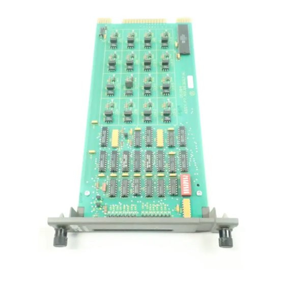
Page 23: Figure 3-2. Address Select Switch (S1)
INSTALLATION OPEN MUST SLAVE REMAIN ADDRESS CLOSED NOTE: OPEN POSITION = LOGIC 1 TP65205A Figure 3-2. Address Select Switch (S1) Table 3-1. Address Switch Settings (S1) Addr Addr 1= OPEN ; 0=CLOSED SETUP/PHYSICAL INSTALLATION I-E96-313A 3 - 3... -
Page 24: Termination Unit/Module Configuration
INSTALLATION ® Termination Unit/Module Configuration A TU/TM connects the field device wiring to the Infi 90 system. The terminal blocks (connection points) are located on the TU/ TM. You must configure the TU/TM to output the DSO signals that are sent to the process field device. Proper polarity wiring of field signals is necessary for the output circuits to function properly. -
Page 25: Wiring Connections And Cabling
INSTALLATION 5. Push and turn the two captive retaining screws on the module faceplate one half turn to the latched position. It is latched when the slots on the screws are vertical and the open ends face the center of the module. (To remove the module, turn the module retaining screws to the unlatched position and gently slide it out). -
Page 26: Figure 3-3. Imdso04 Cable Connections And Termination
INSTALLATION ® GROUP A NKTM01 16 DIGITAL IMDSO04 NIDI01 OUTPUTS NKTU02 GROUP B GROUP A NKTU01 16 DIGITAL IMDSO04 NTDI01 OUTPUTS GROUP B TP27134A Figure 3-3. IMDSO04 Cable Connections and Termination PRE-OPERATING ADJUSTMENTS 3 - 6 I-E96-313A... -
Page 27: Section 4 - Operating Procedures
SECTION 4 - OPERATING PROCEDURES INTRODUCTION This section explains the front panel indicators and start-up procedures for the Digital Slave Output module (IMDSO04). STATUS INDICATORS The Digital Slave Output (DSO) module has a front panel mod- ule status LED indicator to aid in system test and diagnosis. Sixteen front panel indicators display the output states (ON or OFF). -
Page 28: Start-Up Procedures
OPERATING PROCEDURES ® Table 4-1. IMDSO04 Front Panel Indication Solid Green Enabled and communicating with master module No power or not enabled Bus fault timer error ( time-out ) Solid Red START-UP PROCEDURES The master module controls the start-up of the DSO module; it is fully automatic. -
Page 29: Section 5 - Troubleshooting
SECTION 5 - TROUBLESHOOTING INTRODUCTION This section explains the error indications and corrective actions for the Digital Slave Output (DSO) module. ERROR INDICATIONS AND CORRECTIVE ACTION You can obtain the status of the DSO through an Infi 90 opera- tor interface (e.g., Operator Interface Station, Engineering Work Station, Configuration and Tuning Terminal) or the front panel status LED indicators. -
Page 30: Master Module Errors
TROUBLESHOOTING ® Table 5-1. Status LED Indications and Corrective Actions (continued) LED State Indication Probable Cause Corrective Action No power to slave mod- Module not completely inserted Verify module is completely in MMU inserted in MMU: faceplate flush (continued) with MMU and captive retaining screws latched Bus fault timer error Slave expander bus clock failure Check master module for proper... -
Page 31: Module Pin Connections
TROUBLESHOOTING for the procedures to set an address and to install a slave module). 6. Modify the address in the master module configuration (FC 83 specification 1) to correspond with the address set on S1. Use an Infi 90 operator interface to modify the configuration (for procedures on how to modify a function code specification, refer to the Product Instruction for the operator interface you are using). -
Page 32: Table 5-3. P2 Expander Bus Connections
TROUBLESHOOTING ® Table 5-3. P2 Expander Bus Connections Pin(P2) Signal Pin(P2) Signal Data 1 Data 7 Data 0 Data 6 Data 3 Clock Data 2 Sync Data 5 Data 4 NC=Not Connected Table 5-4. P3 Output Signal Pin Connections Group A Group B Digital Digital... -
Page 33: Section 6 - Maintenance
SECTION 6 - MAINTENANCE INTRODUCTION The Digital Slave Output (DSO) module requires limited main- tenance. This section contains a maintenance schedule. MAINTENANCE SCHEDULE Perform the tasks in Table at the specified intervals. Table 6-1. Maintenance Schedule Task Interval Clean and tighten all power and Every 6 months or during plant shut- grounding connections down, whichever occurs first... -
Page 34: Section 7 - Repair/Replacement Procedures
SECTION 7 - REPAIR/REPLACEMENT PROCEDURES INTRODUCTION This section explains the replacement procedures for a Digital Slave Output (DSO) module. There are no special tools required to replace an DSO module. MODULE REPAIR/REPLACEMENT PROCEDURES If you determine the DSO is faulty, replace it with a new one. DO NOT try to repair the module;... -
Page 35: Section 8 - Support Services
SECTION 8 - SUPPORT SERVICES INTRODUCTION Bailey Controls is ready to help in the use, application and repair of its products. Contact your nearest sales office to make requests for sales, applications, installation, repair, overhaul and maintenance contract services. REPLACEMENT PARTS AND ORDERING INFORMATION When making repairs at your facility, order replacement parts from a Bailey sales office. -
Page 36: Appendix A - Termination Unit (Ntdi01) Configuration
APPENDIX A - TERMINATION UNIT (NTDI01) CONFIGURATION INTRODUCTION The IMDSO04 uses an NTDI01 for termination. Dipshunts on the Termination Unit (NTDI01) configure the digital outputs that are sent to the process. The Digital Slave Output (DSO) module outputs switch voltages of 24 VDC at 250 mA. Figure shows the NTDI01 dipshunt without strapping, and the digital signal path from the DSO module to the field device... -
Page 37: Table A-1. Ntdi01 Dipshunt Configuration
TERMINATION UNIT (NTDI01) CONFIGURATION ® Table A-1. NTDI01 Dipshunt Configuration Application/Signal Type Dipshunt Configuration XU1-XU16 Field powered contact XU17 XU1-XU16 System powered from E1, 24 VDC XU17 XU1-XU16 System powered from E2, 24 VDC XU17 TP27139A INTRODUCTION A - 2 I-E96-313A... -
Page 38: Figure A-2. Ntdi01 Terminal Assignments
TERMINATION UNIT (NTDI01) CONFIGURATION DIPSHUNT DIPSHUNT DIPSHUNT DIPSHUNT USED USED USED USED XU13 – – – – XU14 XU10 – – – – TERMINAL NUMBER XU15 XU11 – – – – XU16 XU12 – – – – TP27163A Figure A-2. NTDI01 Terminal Assignments INTRODUCTION I-E96-313A A - 3... -
Page 39: Appendix B - Termination Module (Nidi01) Configuration
APPENDIX B - TERMINATION MODULE (NIDI01) CONFIGURATION INTRODUCTION The IMDSO04 uses an NIDI01 for termination. Jumpers on the Termination Module (NIDI01) configure the digital outputs that are sent to the process. The Digital Slave Output (DSO) module outputs switch voltages of 24 VDC at 250 mA. Refer to Table to determine the jumper setting to configure your applica- tion. - Page 40 Telefax 39-10-6582-941 Telephone 49-69-799-0 Telefax 65-292-9011 Telefax 49-69-799-2406 Form I-E96-313A Litho in U.S.A. 690 Copyright © 1990 by Elsag Bailey Process Automation, As An Unpublished Work ® Registered Trademark of Elsag Bailey Process Automation ™ Trademark of Elsag Bailey Process Automation...
Need help?
Do you have a question about the Infi 90 IMDSO04 and is the answer not in the manual?
Questions and answers