
Related Manuals for Bailey Infi 90 IMLMM02


Summary of Contents for Bailey Infi 90 IMLMM02
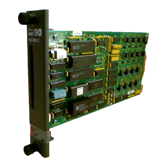
- Page 1 E96-209 ® ® Logic Master Module (IMLMM02) Process Control and Automation Solutions from Elsag Bailey Group...
- Page 2 The information contained in this document is subject to change without notice. Elsag Bailey, its affiliates, employees, and agents, and the authors and contributors to this publication specif- ically disclaim all liabilities and warranties, express and implied (including warranties of merchantability and...
- Page 3 The following hardware, as it applies, is mentioned as well: Termination Units/modules: NTDI01, NTDO02, NIDI01, NIDO01 Termination Unit Cables: NKTU01, NKTM01, NKTU02 Digital Slave Modules: IMDSM04, IMDSM05,} IMDSI02, IMDSO01, IMDSO02, IMDSO03, IMDSO04 ® INFI 90 is a registered trademark of the Elsag Bailey Process Automation. I-E96-209A...
- Page 4 ® List of Effective Pages Total number of pages in this manual is 36, consisting of the following: Page No. Change Date Preface Original List of Effective Pages Original iii through vii Original 1-1 through 1-6 Original 2-1 through 2-6 Original 3-1 through 3-7 Original...
- Page 5 ® Safety Summary GENERAL Equipment Environment WARNINGS All components, whether in transportation, operation or storage must be in a noncorrosive environment. Electrical Shock Hazard During Maintenance Disconnect power or take precautions to ensure that contact with energized parts is avoided when servicing. Special Handling This module uses Electrostatic Sensitive Devices (ESD).
- Page 6 Sommaire de Sécurité AVERTISSEMENTS Environment de l'equipement D’ORDRE Nes pas soumettre les composantes a une atmosphere corrosive GÉNÉRAL lors du transport, de l'entreposage ou de l'utilisation. Risques de chocs electriques lor de l'entretien S'assurer de debrancher l'alimentation ou de prende les precau- tions necessaires a eviter tout contact avec des composants sours tension lors de l'entretien.
-
Page 7: Table Of Contents
Table of Contents Page SECTION 1 - INTRODUCTION ....................1-1 OVERVIEW ........................1-1 INTENDED USER ......................1-1 MODULE DESCRIPTION ....................1-1 MODULE APPLICATION ....................1-1 INSTRUCTION CONTENT .....................1-1 HOW TO USE THIS MANUAL ..................1-2 REFERENCE DOCUMENTS..................1-2 GLOSSARY OF TERMS AND ABBREVIATIONS .............1-3 NOMENCLATURE ......................1-4 SPECIFICATIONS ......................1-5 SECTION 2 - DESCRIPTION AND OPERATION................2-1 INTRODUCTION......................2-1 FUNCTIONAL OPERATION ...................2-1... - Page 8 ® Table of Contents (continued) Page SECTION 4 - OPERATING PROCEDURES (continued) LED INDICATORS......................4-1 Status LED......................4-1 Input/Output LEDs....................4-2 RESET SWITCH ......................4-2 START-UP PROCEDURES .................... 4-2 SECTION 5 - TROUBLESHOOTING...................5-1 INTRODUCTION ......................5-1 ERROR INDICATIONS AND CORRECTIVE ACTION ............5-1 Logic Master Module Indicators ................
- Page 9 List of Figures Title Page 2-1. Logic Master Module Block Diagram ..............2-1 3-1. Logic Master Module ....................3-2 3-2. Module Address Switch (S2) ...................3-3 4-1. LMM Front Panel ....................4-2 I-E96-209A...
-
Page 10: Section 1 - Introduction
SECTION 1 - INTRODUCTION OVERVIEW The Logic Master Module (IMLMM02) is an INFI 90 module that performs multiple calculating and control functions. The LMM contains onboard circuitry for eight digital inputs and eight digital outputs. It also interfaces with up to 64 digital I/O slaves through the slave expander bus for additional I/O capa- bility. -
Page 11: How To Use This Manual
Procedures Support Services Provides replacement part ordering information. It explains other areas of support that Bailey Controls provides. HOW TO USE THIS MANUAL Read this manual through in sequence. It is important to become familiar with the entire contents of this manual before using the LMM. -
Page 12: Glossary Of Terms And Abbreviations
INTRODUCTION GLOSSARY OF TERMS AND ABBREVIATIONS Term Description Configuration and Tuning Module. Provides a local means for system configuration, tuning, and monitoring of intelligent masters over module bus. Configuration and Tuning Terminal. A handheld module with the same functionality as the Configuration and Tuning Module. Checksum A value computed from a data stream by treating each element as a number and computing the sum of the elements. -
Page 13: Nomenclature
INTRODUCTION ® GLOSSARY OF TERMS AND ABBREVIATIONS (continued) Term Description Operator Interface Station. Integrated operator console with data acquisition and reporting capabilities. It provides a digital access into the process for flexible control and monitoring. Process Control Unit. A node on the plant wide communication network containing master and slave modules. -
Page 14: Specifications
INTRODUCTION SPECIFICATIONS Memory Random Access Memory (RAM) 16 Kbytes Read Only Memory (ROM) 32 Kbytes Nonvolatile Random Access Memory 8 Kbytes (NVRAM) Power Requirements Voltage +5 VDC (±5%) Current 525 mADC (maximum) 450 mADC (nominal) Input Voltage Ranges 24 VDC Logic High 16.3 VDC (minimum) Logic Low... - Page 15 INTRODUCTION ® SPECIFICATIONS (continued) CSA certified for use as process control equipment in an ordi- Certification nary (nonhazardous) location. Environmental Ambient Temperature 0° to 70° C (32° to 158° F) 0% to 95% up to 55° C (131° F) (noncondensing) Relative Humidity 0% to 45% at 70°...
-
Page 16: Section 2 - Description And Operation
SECTION 2 - DESCRIPTION AND OPERATION INTRODUCTION This section explains the functions, module circuitry, data and connections for the Logic Master Module (IMLMM02). It also details the function codes available to configure an LMM. FUNCTIONAL OPERATION The logic master module consists of six major sections. They are Memory, Module Bus Interface, Machine Fault Timer, Slave Expander Bus Interface, Digital Inputs/Outputs, and the Microprocessor, Timing and Control section. -
Page 17: Slave Expander Bus Interface
DESCRIPTION AND OPERATION ® identifies the module. The device address for the logic master module is set via an eight position dipswitch. NOTE: The LMM cannot communicate over the controlway. Slave Expander Bus Interface The slave expander bus interface on the logic master module allows it to communicate with up to 64 digital slave modules that interface with additional I/O based on the user's require- ments. -
Page 18: Digital Inputs/Outputs
DESCRIPTION AND OPERATION Digital Inputs/Outputs There are eight digital inputs and eight digital outputs on-board. The inputs are jumper-selectable to be energized by 24 VDC, 125 VDC or 120 VAC. The inputs are optically-iso- lated; outputs are optically-isolated open-collector type. The I/ O signals are routed to the NTDI01/NTDO02 TU or the NIDI01/NIDO01 TM through the NKTU01, NKTM01, or NKTU02 cable connection on the P3 card edge connector. -
Page 19: Function Blocks
DESCRIPTION AND OPERATION ® Function Blocks NOTE: Refer to the Function Code Application Manual, I-E93-900-20 for the specifications and outputs of the LMM function codes. The range of function blocks for the logic master module is 0 through 1,023. Blocks 0 through 23 are reserved for the execu- tive block and outputs of all the fixed address system blocks. -
Page 20: Function Codes
DESCRIPTION AND OPERATION executable functions. The block numbers column is the range of user-assignable block numbers. Table 2-2. Function Codes Function Block Description Code Numbers Manual Set Constant 24-1023 Square Root 24-1023 High Select 24-1023 Low Select 24-1023 High/Low Compare 24-1023 Sum-4 Inputs 24-1023... - Page 21 DESCRIPTION AND OPERATION ® Table 2-2. Function Codes (continued) Function Block Description Code Numbers Up/Down Counter 24-1021 Logic Station Interface 24-1023 Logic Station 24-1015 XOR - 2 Input 24-1023 Executive Segment Control Block 15,24-1019 Group I/O Definition 24-831 5 Input Rung 24-1023 10 Input Rung 24-1023...
-
Page 22: Section 3 - Installation
SPECIAL HANDLING NOTE: Always use Bailey's Field Static Kit (P/N 1948385A2 - con- sists of wrist strap, ground cord assembly, alligator clip) when work- ing with modules. The kit is designed to connect a technician and the static dissipative work surface to the same ground point to pre- vent damage to the modules by electrostatic discharge. -
Page 23: Setup/Physical Installation
INSTALLATION ® SETUP/PHYSICAL INSTALLATION NOTE: The Installation section provides instructions pertaining to the installation of the LMM only. For complete TU/TM installation, wiring and cable information, refer to the Termination Unit Manual I-E93-911 . This section explains the procedures to set switches and jump- ers, and install the LMM. -
Page 24: Module Address Switch (S2) Settings
INSTALLATION MODULE ADDRESS SWITCH (S2) SETTINGS The module address switch sets the hardware operating states (run modes or diagnostic modes) and module address of the LMM. Figure shows the location of S2. During normal oper- ation, dipswitch positions 1 through 3 set the run mode and positions 4 through 8 set the module address as shown in Fig- ure 3-2. -
Page 25: Module Address Settings (S2)
INSTALLATION ® Initialize NVRAM Initialize NVRAM is set to clear any existing configuration from nonvolatile random access memory (NVRAM). This initializes the NVRAM prior to entering a configuration, and should be done before loading a new configuration. The LMM status LED will blink green to indicate that initialization is complete. -
Page 26: Digital Input Jumper Settings
INSTALLATION DIGITAL INPUT JUMPER SETTINGS There are eight on-board jumpers (J1 through J8) that select the type of digital input signals (24 VDC, 125 VDC, or 120 VAC) being monitored. 1. Jumper pins 1 and 2 together to configure the inputs for 125 VDC or 120 VAC signals. -
Page 27: Slave Expander Bus Connection
INSTALLATION ® NIDI01 High density, modular version of the NTDI01. Jumper select- able for slave type. NIDO01 High density, modular version of NTDO02. Interfaces field digi- tal I/O to digital slaves, provides onboard power distribution for outputs. Jumper selectable for slave type. Slave Expander Bus Connection When an LMM is used with slave modules, they make up a master/slave subsystem within a Process Control Unit (PCU). -
Page 28: Cable Connections
INSTALLATION Cable Connections Three cables connect the I/O to the LMM. The cable required depends on the associated hardware being used to provide support for the LMM functions. Digital inputs/outputs from an NTDI01 or NTDO02 Termi- • nation Unit to the LMM. Digital inputs/outputs from an NIDI01 or NIDO01 Termi- •... -
Page 29: Section 4 - Operating Procedures
SECTION 4 - OPERATING PROCEDURES INTRODUCTION This section explains the modes of operation, front panel indi- cators and start-up procedures for the Logic Master Module (IMLMM02). MODES OF OPERATION The logic master module (LMM) has three modes of operation: EXECUTE, CONFIGURE, and ERROR mode. The mode can be changed using an operator interface. -
Page 30: Input/Output Leds
OPERATING PROCEDURES ® IMLMM02 MODULE STATUS OUTPUT LEDS INPUT LEDS RESET SWITCH ACCESS TP21033A Figure 4-1. LMM Front Panel Input/Output LEDs Group A and Group B LEDs are numbered one through eight. When an output is active, its corresponding Group A LED is red. When an input is active, its corresponding Group B LED is red. -
Page 31: Section 5 - Troubleshooting
NOTE: If the corrective actions in this section do not correct a prob- lem with these modules, replace the module or contact your nearest Bailey Controls representative. Refer to the repair/replacement sec- tion for procedures to replace an LMM. ERROR INDICATIONS AND CORRECTIVE ACTION The status of the LMM can be obtained through an operator interface or the front panel LED indicators. -
Page 32: Status Bytes
Refer to Table 5-2. Module in ERROR mode. A fatal error has Replace module or contact nearest Bailey LMM does not communi- occurred Controls representative. cate with modules on module bus. - Page 33 TROUBLESHOOTING Table 5-2. Module Status Bytes (continued) Field Field Size or Value Description BYTE 1 Error Summary (0=OK, 1=ERRORS), 11=EXT) MODE Module Mode (00=CFG, 10=ERR TYPE Module Type Code =(C) BYTE 2 First Time in Execute (0=NO, 1=YES) Memory Overflow (0=NO, 1=YES) Summary Remote Input Status (0=OK, 1=BAD) Summary Local Input Status (0=OK, 1=BAD) Summary NVRAM Failure State (0=OK, 1=BAD)
-
Page 34: Connector Pinouts
TROUBLESHOOTING ® CONNECTOR PINOUTS Tables show the pinouts for the LMM edge connectors. Table 5-3. P1 Pinout Signal Signal +5 VDC +5 VDC Common Common +15 VDC -15 VDC Module Bus Module Bus NOTE: PFI = Power Fail Interrupt Table 5-4. P2 Pinout Signal Signal Data Bit D1... -
Page 35: Section 6 - Maintenance
SECTION 6 - MAINTENANCE INTRODUCTION The Logic Master Module (IMLMM02) requires limited mainte- nance. This section contains a maintenance schedule. MAINTENANCE SCHEDULE Perform the tasks in Table6-1 at the specified intervals. Table 6-1. Maintenance Schedule Task Interval Clean and tighten all power and Every 6 months or during plant shut- grounding connections. -
Page 36: Section 7 - Repair/Replacement Procedures
SECTION 7 - REPAIR/REPLACEMENT PROCEDURES INTRODUCTION This section explains the replacement procedures for a Logic Master Module (IMLMM02). There are no special tools required to replace these modules. MODULE REPAIR/REPLACEMENT PROCEDURES If you determine an LMM is faulty, replace it with a new one. DO NOT try to repair the module;... -
Page 37: Section 8 - Support Services
Contact a Bailey Controls sales office for specific information and scheduling. TECHNICAL DOCUMENTATION Additional copies of this manual, or other Bailey Controls man- uals, can be obtained from the nearest Bailey sales office at a reasonable charge. INTRODUCTION I-E96-209A... - Page 38 Index Configure ............4-1 Error ..............4-1 Cable connections ............3-7 Execute ............4-1 Configuration ............2-3, 3-7 Module address switch (S2) settings ....3-3 Function blocks............. 2-4 Address ............3-4 Function codes ............. 2-4 Run mode ............3-3 Connector pinouts ............5-4 Module description ..........1-1 Physical installation..........3-5 Startup procedures..........4-2 Digital input jumpers ...........
- Page 39 Telefax 39-10-6582-941 Telephone 49-69-799-0 Telefax 65-292-9011 Telefax 49-69-799-2406 Form I-E96-209A Litho in U.S.A. 891 Copyright © 1991 by Elsag Bailey Process Automation, As An Unpublished Work ® Registered Trademark of Elsag Bailey Process Automation ™ Trademark of Elsag Bailey Process Automation...
Need help?
Do you have a question about the Infi 90 IMLMM02 and is the answer not in the manual?
Questions and answers