
Related Manuals for Bailey Infi 90 IMCPM03


Summary of Contents for Bailey Infi 90 IMCPM03
- Page 1 E96-225 ® ® Communication Port Module (IMCPM03) Process Control and Automation Solutions from Elsag Bailey Group...
- Page 2 The information contained in this document is subject to change without notice. Elsag Bailey, its affiliates, employees, and agents, and the authors and contributors to this publication specif- ically disclaim all liabilities and warranties, express and implied (including warranties of merchantability and...
- Page 3 It is important for safety and operating reasons to first read and understand this manual completely; do not install or com- plete any tasks or procedures related to operation before read- ing it. ® PCV and INFI 90 are registered trademarks of Elsag Bailey Process Automation. I-E96-225A...
- Page 4 ® List of Effective Pages Total number of pages in this instruction is 58, consisting of the following: Page No. Change Date Preface Original List of Effective Pages Original iii through viii Original 1-1 through 1-6 Original 2-1 through 2-5 Original 3-1 through 3-13 Original...
- Page 5 ® Safety Summary GENERAL Equipment Environment WARNINGS All components, whether in transportation, operation or storage, must be in a noncorrosive environment. Electrical Shock Hazard During Maintenance Disconnect power or take precautions to insure that contact with energized parts is avoided when servicing. Special Handling This module uses electrostatic sensitive devices.
- Page 6 Sommaire de Sécurité AVERTISSEMENT Environnement de l’équipement D’ORDRE Ne pas soumettre les composants à une atmosphère corrosive lors GENERAL du transport, de l’entreposage ou l’utilisation. Possibilité de chocs électriques durant l’entretien Débrancher l’alimentation ou prendre les précautions pour éviter tout contact avec des composants sous tension durant l’entretien. Précautions de manutention Ce module contient des composants sensibles aux décharges élec- trostatiques.
- Page 7 ® Sommaire de Sécurité (suite) ATTENTION S’assure que tous les dipshunts de la carte de raccordment sont D’ORDRE configurés avant de mettre sous tension. Un dommage à la carte de SPECIFIQUE raccordement peut être causé si on ne prend pas cette précaution. (p.
-
Page 8: Table Of Contents
Table of Contents Page SECTION 1 - INTRODUCTION ....................1-1 OVERVIEW ........................1-1 INTENDED USER ......................1-2 DESCRIPTION......................1-2 Faceplate .......................1-2 Circuit Board ......................1-3 INSTRUCTION CONTENT .....................1-3 HOW TO USE THIS INSTRUCTION ................1-3 REFERENCE DOCUMENTS..................1-4 GLOSSARY OF TERMS AND ABBREVIATIONS .............1-5 NOMENCLATURE ......................1-5 SPECIFICATIONS ......................1-6 SECTION 2 - DESCRIPTION AND OPERATION................2-1 INTRODUCTION......................2-1 THEORY OF OPERATION .....................2-1... - Page 9 ® Table of Contents (continued) Page SECTION 4 - OPERATION (continued) RESET SWITCH ......................4-2 ON-LINE HARDWARE DIAGNOSTICS ................4-2 SECTION 5 - TROUBLESHOOTING...................5-1 INTRODUCTION ......................5-1 LED DISPLAY ......................5-1 LED ERROR CODES ....................5-1 CONNECTORS......................5-2 Power ........................5-2 Input and Output ....................
- Page 10 List of Figures Title Page 1-1. IMCPM03 Module Application Example ..............1-1 2-1. Block Diagram of the IMCPM03 Module ..............2-1 3-1. Switch and Jumper Positions .................3-3 3-2. Schematic Diagram of Jumpers J1 through J5 ............3-4 3-3. DCE Setting for Jumper Array J5 and J6 ...............3-5 3-4.
-
Page 11: Section 1 - Introduction
EWS work station or a LAN-90 PCV operator console. The IMCPM03 module minimizes hardware requirements. CONTROLWAY/MODULE BUS LAN-90 IMCPM03 IMCPM03 I/O EXPANDER BUS MODULE MODULE TP36332A Figure 1-1. IMCPM03 Module Application Example ™ LAN-90 is a trademark of Elsag Bailey Process Automation. I-E96-225A 1 - 1... -
Page 12: Intended User
Elsag Bailey’s consoles, software tools and software application products with the INFI 90 Open system. Elsag Bailey offers a full range of other products for integrating non-Elsag Bailey applications with the INFI 90 Open system. The IMCPM03 interfaces the CTT terminal and EWS station to the Controlway or module bus through faceplate connectors. -
Page 13: Circuit Board
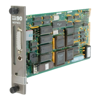
INTRODUCTION Circuit Board The circuit board has static random access memory (SRAM), read-only memory (ROM), a processor running at 16 megahertz and direct memory access (DMA) circuits. The circuit board also has custom bus circuits and support circuitry. The board attaches to the faceplate with two screws. -
Page 14: Reference Documents
INTRODUCTION ® specific sections. Elsag Bailey strongly advises against putting the module into operation until all the installation steps have been read and completed. Be sure to read the notes which provide: Additional information. • Information that should be considered before performing a •... -
Page 15: Glossary Of Terms And Abbreviations
INTRODUCTION GLOSSARY OF TERMS AND ABBREVIATIONS Refer to Table for those terms and abbreviations that are unique to Elsag Bailey or have a definition that is different from standard industry usage. Table 1-2. Glossary of Terms and Abbreviations Term Description Engineering work station. -
Page 16: Specifications
INTRODUCTION ® SPECIFICATIONS Refer to Table for the specifications for the IMCPM03 mod- ule. Table 1-4. Specifications Property Characteristics 0.81 A maximum, 750 mA typical, at +5 VDC Current Consumption Power Dissipation 4.1 W maximum, 3.8 W typical Microprocessor 32 bit processor (16 bit external bus) running at 16 MHz Memory 256 kbytes of ROM 512 kbytes of RAM... -
Page 17: Section 2 - Description And Operation
SECTION 2 - DESCRIPTION AND OPERATION INTRODUCTION The IMCPM03 module hardware contains several functional blocks working together. To understand how they work, this section shows them in a block diagram and then explains each block in the text. Refer to Figure 2-1. CLOCK/TIMER MACHINE FAULT... -
Page 18: Db-25 Computer Port
The serial channel is normally used to interface the Elsag Bailey hardware when the IMCPM03 module is in the data communication equipment (DCE) mode (determined by jumper configuration). It also may be connected to a modem when the IMCPM03 module is in data terminal equipment (DTE) mode (determined by jumper configuration). -
Page 19: Ctt Port
DESCRIPTION AND OPERATION CTT PORT The IMCPM03 module communicates with the CTT terminal via the round five-pin connector on the faceplate. Messages received from the CTT terminal are transmitted on Controlway or module bus, but using the source module address of the IMCPM03 module in place of the module address of the CTT terminal. -
Page 20: Module Bus And Controlway
Controlway is a one megabaud peer-to-peer communication link capable of supporting up to 32 drops. The Controlway interface is provided by a custom Elsag Bailey integrated cir- cuit that links the IMCPM03 module to Controlway. It has full direct memory access (DMA) capabilities which permit quicker operation, and two redundant independent channels. -
Page 21: Dipswitches
DESCRIPTION AND OPERATION Dipswitches Each dipswitch has eight poles. • Dipswitch SW2 sets module options. • Dipswitch SW3 sets the module address. • A reset switch (SW1) accessed through the faceplate resets • the module. Jumpers Jumpers J1 through J3 enable handshake functions for •... -
Page 22: Section 3 - Installation
IMCPM03 module into the system. Refer Jumper Installation SPECIAL HANDLING Always use the Elsag Bailey Field Static Kit (part number 1948385 1) consisting of two wrist straps, ground cord assembly, alligator clip, and static-dissipating work surface when working with modules. -
Page 23: General Handling
Installation. 1. Examine the hardware immediately to verify that it has not been damaged in transit. 2. Notify the nearest Elsag Bailey sales office of any such damage. 3. File a claim for any damage with the transportation com- pany that handled the shipment. -
Page 24: Switch And Jumper Positions
INSTALLATION S TAT U S IM C P M 0 3 L ED s 9 1 0 9 1 0 R ES ET S W IT C H S W 1 SW 2 S W 3 1 2 3 5 6 7 8 1 2 3 4 5 6 7 8 O P E N... -
Page 25: Jumpers J1 Through J3
INSTALLATION ® +12 VDC J1, J2, J3, J4 DB25-6 DB25-8 DB25-20 PROT-GND DB25-1 DB25-7 ACOMM TXD-A DB25-3 RXD-A DB25-2 RTS-A DB25-4 CTS-A DB25-5 TP36053A Figure 3-2. Schematic Diagram of Jumpers J1 through J5 JUMPERS J1 THROUGH J3 Jumpers J1, J2 and J3 enable the handshake functions for the DB-25 computer port (P4) and must be set to match the equip- ment used. -
Page 26: Jumper J4
INSTALLATION JUMPER J4 Jumper J4 connects the shield of the RS-232-C connector cable to chassis ground through the IMCPM03 module. The cable shield should be grounded at either end, but never both ends. If the cable shield is grounded at the console or station end, short pins 2 and 3 of jumper J4. -
Page 27: Jumpers J11 And J12
INSTALLATION ® message is then sent after the receiving device replies to the request. The handshake function may be disabled for applica- tions requiring special communications. JU M P E R S J5 ,J6 JU M P E R S J5 ,J6 D T E W IT H N O H A N D S H A K E D T E W IT H H A N D S H A K E TP36056A... -
Page 28: Dipswitch Settings
INSTALLATION way in redundant mode. Refer to Figure for the schematic of jumpers J11 and J12. MODULE BUS A P1-11 MODC JMODA MODULE BUS B P1-4 JMODB TP36058B Figure 3-6. Schematic Diagram of Jumpers J11 and J12 DIPSWITCH SETTINGS The module has two configurable dipswitches, SW2 and SW3. The dipswitches have eight poles. -
Page 29: Dipswitch Sw2 - Normal Operation Mode
INSTALLATION ® Diagnostic mode - When operated in the diagnostic mode, the IMCPM03 does not function as an IMCPM03 module. The diag- nostic mode tests the operation of the module components and circuitry. Refer to Section 5 for diagnostic dipswitch setting information. -
Page 30: Dipswitch Sw3 - Normal Operation Mode
INSTALLATION Table 3-1. Dipswitch SW2 Option Settings for Normal Mode (continued) SW2 Pole Settings Option DB-25 computer port baud rate and DB-9 EWS port baud rate Computer 19200 1200 19200 2400 19200 9600 1200 1200 2400 2400 9600 2400 9600 9600 19200 19200... -
Page 31: Spm/Cpm02 Mode
INSTALLATION ® When the IMCPM03 is operating in database mode, the module can only have a module address of 0 or 1. NOTE: If a CTT terminal is used, set the CTT terminal and the IMCPM03 module to the same module address to avoid duplicate address conflicts with the other modules of the process control unit. -
Page 32: Database Mode
INSTALLATION DATABASE MODE NOTE: Because an IMCPM03 module in database mode is respon- sible for collecting all exception reports in a PCU, there are some important considerations for its use. No more than one IMCPM03 module operating in the database mode can operate on the Control- way or module bus at the same time. -
Page 33: Installing The Module
VDC supply wiring Faston or set jumper J12 before installing the IMCPM03 module. 4. Set jumper J12 correctly. Refer to Jumper Installation. 5. For additional information or assistance, contact Elsag Bailey technical support. ™ Faston is a trademark of Amp Incorporated. 3 - 12 I-E96-225A... -
Page 34: Installing The Termination Unit Or Module
INSTALLATION 6. Before installing the module, check all dipswitch and jumper settings, and ensure that respective module cables are attached to the MMU backplane. The IMCPM03 module can be installed and removed under power. Installing the module with power applied causes the status LED to turn red momentarily and then turn green. -
Page 35: Section 4 - Operation
SECTION 4 - OPERATION INTRODUCTION This section explains what happens during start-up, what the LED indicators mean, and how to reset the module. START-UP The IMCPM03 module checks its hardware at start-up by using power up diagnostics to verify that it is working. The eight red status LEDs turn off when this operation is complete. -
Page 36: Reset Switch
OPERATION ® the status of the Controlway channel A (on=ok), and LED 8 dis- plays the status of Controlway channel B (on = ok). When the IMCPM03 is in the failed mode, these LEDs indicate module error codes. If an error occurs, the IMCPM03 module status LED turns red and LEDs 1 through 8 light up to display the error code (refer to Table 5-1). -
Page 37: Section 5 - Troubleshooting
SECTION 5 - TROUBLESHOOTING INTRODUCTION This section contains faceplate LED error codes, edge connec- tor pinouts, cable connector pinouts, and explains the use of diagnostic tests. LED DISPLAY The IMCPM03 module has one two-color status LED on the faceplate to indicate the execute or failed status of the module (refer to Figure 3-1). -
Page 38: Connectors
TROUBLESHOOTING ® Table 5-1. Red Status LED Error Codes (continued) Code LEDs Error Condition Corrective Action (Hex) 8 7 6 5 4 3 2 1 0 0 1 1 0 0 1 0 Address or bus error Reset IMCPM03 module. If error recurs, replace the module. -
Page 39: Ctt Port
TROUBLESHOOTING Table 5-3. Termination Unit Signals, P3 Edge Connector Signal Signal (NC) (NC) (NC) (NC) (NC) (NC) (NC) (NC) (NC) (NC) (NC) (NC) Serial RXD A- Serial RXD A+ Serial RXD B- Serial RXD B+ Serial CTS A- Serial CTS A+ Serial CTS B- Serial CTS B+ Serial TXD A-... -
Page 40: Db-9 Ews Port
TROUBLESHOOTING ® Table 5-5. Computer Port Signals, P4 Connector Signal Protective ground Transmitted data (TXD) Received data (RXD) Request to send (RTS) Clear to send (CTS) Data set ready (DSR) Common Data carrier detect (DCD) Data terminal ready (DTR) DB-9 EWS Port The IMCPM03 provides a DB-9 connector inside the faceplate on the circuit board for use as an EWS port. -
Page 41: Test Descriptions
TROUBLESHOOTING 2. Select a diagnostic test to run, then set the dipswitches and reset the module. Observe the test results on the faceplate LED display. The selected test runs repeatedly until the IMCPM03 module is reset or another test is selected on dipswitch SW2. Test Descriptions The IMCPM03 module has 12 self-contained diagnostic tests that can be run to identify hardware failures. -
Page 42: Dipswitch Settings
TROUBLESHOOTING ® Dipswitch Settings This section describes the settings and function of dipswitches SW2 and SW3 for diagnostic mode. Refer to Figure for the dipswitch locations on the IMCPM03 module. J 11 S TAT U S J 1 2 I M C P M 0 3 L E D s 9 1 0 9 1 0... -
Page 43: Dipswitch Sw3 Settings - Diagnostics
TROUBLESHOOTING Table 5-8. Dipswitch SW2 Settings for Diagnostic Mode (continued) Test SW2 Pole Settings Diagnostic Test Test CPU ROM (verify ROM check- sum) Test RAM Test module bus or Control- Test DUART timer interrupt Test dispatcher interrupt Test DUART serial channels (local loopback mode) Test CTT module bus Null test... -
Page 44: Leds - Pass Or Fail
TROUBLESHOOTING ® If pole 1 on SW2 is OFF, a running tally of successes and fail- ures will be displayed on the LEDs. LEDs 1 through 4 tally the passes, LEDs 5 through 8 tally the failures. D IP S W IT C H S W 3 P O L E 1 O N P O L E 1 O F F L E D s... -
Page 45: Section 6 - Maintenance
The reliability of any stand-alone product or control system is affected by the maintenance of that equipment. Elsag Bailey Process Controls recommends that all equipment users prac- tice a preventive maintenance program that will keep the equipment operating at an optimum level. -
Page 46: Equipment And Tools Required
MAINTENANCE ® Table 6-1. Preventive Maintenance Schedule (continued) Task Frequency Inspect and check the module giving particular attention 12 months to edge connectors. Clean as necessary. Refer to proce- dure. Complete all tasks in this table. Shutdown EQUIPMENT AND TOOLS REQUIRED Following are the tools and equipment required for mainte- nance procedures. -
Page 47: General Cleaning And Washing
MAINTENANCE Do all cleaning and handling of the printed circuit boards at static safe work stations. Always observe the proper electro- static discharge handling precautions when handling printed circuit boards. General Cleaning and Washing If the printed circuit board needs minor cleaning, remove dust and residue from its surface using clean, dry, filtered com- pressed air or an antistatic field service vacuum cleaner. -
Page 48: Section 7 - Repair/Replacement Procedures
SECTION 7 - REPAIR/REPLACEMENT PROCEDURES INTRODUCTION Repair procedures are limited to module replacement. If the IMCPM03 module fails, remove and replace it with another module. Verify that firmware revision levels match and that replacement switch settings are the same as the failed module. Refer to Table for a list of recommended spare parts. -
Page 49: Section 8 - Support Services
SECTION 8 - SUPPORT SERVICES INTRODUCTION Bailey Controls Company is always ready to assist in the oper- ation and repair of its products. Send requests for sales or application services to the nearest sales or service office. Bailey Controls Company can also provide installation, repair and maintenance contract services. -
Page 50: Appendix A - Enhanced Module Status
APPENDIX A - ENHANCED MODULE STATUS ENHANCED MODULE STATUS This section contains the enhanced module status format of the IMCPM03. This block is displayed when the Demand Mod- ule Status command is issued on the CTT. Refer to Table for the enhanced module status block and Table for the enhanced module status block code description. -
Page 51: Enhanced Module Status
ENHANCED MODULE STATUS ® Table A-2. Enhanced Module Status Block Code Description Field Description ES (Error summary) 0 = no errors 1 = error exists (check other fields) MODE 0 = configure 1 = failed (not used) 3 = execute Module type ( = 21) Enhanced module type (refer to Enhanced module type field) -
Page 52: Jumper Configuration For Modem (Dce) Connection
APPENDIX B - NIMP01/02 TERMINATION MODULE INTRODUCTION The IMCPM03 module can use the NIMP01/02 termination module for termination. Refer to Figure for the jumper con- figuration required for connection to a modem. Refer to Figure for the jumper configuration required to operate as an EWS port. -
Page 53: Handshake Signal Schematic
NIMP01/02 TERMINATION MODULE ® +12 V J19 AND J20 DB9-8 J6 AND J8 DB9-6 J5 AND J9 DB9-1 J7 AND J10 DB9-4 NOTES: 1. JUMPERS J20, J8, J9 AND J10 RELATE TO CONNECTOR P6. DB9-5 2. JUMPERS J19, J6, J5 AND J7 RELATE TO CONNECTOR P5. -
Page 54: Appendix B - Nimp01/02 Termination Module
NIMP01/02 TERMINATION MODULE CHASSIS GROUND SYSTEM COMMON +24 VDC TERMINAL PORT (RS-232-C) PRINTER PORT (RS-232-C) RS-485 PORT SPARE DIGITAL INPUT SERIAL LINK LINK B FOR STATIONS FUSE F1 LINK A IF REQUIRED NIMP02 REDUNDANCY CABLES ATTACH HERE TP50354B Figure B-6. Connector Assignments and Jumper Locations N K T U 0 2 I M C P M 0 3 N IM P 0 1... -
Page 55: Introduction
APPENDIX C - NTMP01 TERMINATION UNIT INTRODUCTION The IMCPM03 module can use the NTMP01 termination unit for termination. Refer to Figure for the jumper configura- tion required for connection to a modem. Refer to Figure for the jumper configuration required to operate as a computer port. -
Page 56: Handshake Signal Schematic
NTMP01 TERMINATION UNIT ® +12 V J6 AND J8 DB25-6 J5 AND J9 DB25-8 J7 AND J10 DB25-20 J4 AND J3 PROT-GND DB25-1 DB25-7 NOTE: JUMPERS J3, J8, J9 AND J10 RELATE TO THE P6 CONNECTOR. JUMPERS J4, J5, J6 AND J7 RELATE TO THE P5 CONNECTOR. -
Page 57: Connector Assignments And Jumper Locations
NTMP01 TERMINATION UNIT EW S PORT 1 (EN GIN EER IN G W O R K STATIO N ) J1 6 + 2 4 V J1 7 CR 1 J 12 FUSE F1 SPAR E C O M D IAG N O STIC TO P 3 O N PO RT 2 CR 2... - Page 58 Index 0B - Dispatcher interrupt test ........5-5 0C - RS-232 DUART external loopback test ..5-5 Abbreviations and terms..........1-5 0C - RS-232 DUART test ........5-5 0F - Null test ............5-5 11 - Loopback test..........5-5 Diagnostics Block diagram Hardware............4-2, 5-4 Application example..........1-1 Pass or fail LEDs...........5-8 Module ..............
- Page 59 ® Index (continued) Installation ............3-12 P1, power.............. 5-2 Overview ...............1-1 P3, input and output..........5-2 Replacement ............7-1 P4, CTT port ............5-3 Special handling ............3-1 P5, computer port ..........5-3 Specifications ............1-6 P6, utility port ..........2-3, 5-4 Start-up..............4-1 Module mounting unit Theory of operation ..........2-1 Pin outs..............
- Page 60 Index (continued) Replacement............8-1 Spare parts Spare ..............7-1 List.................7-1 Permanent module installation ......... 3-13 Ordering ..............8-1 Pin outs Special handling............3-1 Computer port............5-4 Specifications, module ..........1-6 CTT port..............5-3 SPM mode, SW3 ............3-10 Input and output signals........5-3 Startup, module............4-1 Module mounting unit ...........
- Page 61 Telefax 39-10-6582-941 Telephone 49-69-799-0 Telefax 65-292-9011 Telefax 49-69-799-2406 Form I-E96-225A Litho in U.S.A. 1095 Copyright © 1995 by Elsag Bailey Process Automation, As An Unpublished Work ® Registered Trademark of Elsag Bailey Process Automation ™ Trademark of Elsag Bailey Process Automation...
Need help?
Do you have a question about the Infi 90 IMCPM03 and is the answer not in the manual?
Questions and answers