
Related Manuals for Bailey Infi 90 IMDSO01


Summary of Contents for Bailey Infi 90 IMDSO01
- Page 1 E96-310 ® ® Digital Output Module (IMDSO01/02/03) Process Control and Automation Solutions from Elsag Bailey Group...
- Page 2 The information contained in this document is subject to change without notice. Bailey Controls Company, its affiliates, employees, and agents, and the authors and contributors to this pub- lication specifically disclaim all liabilities and warranties, express and implied (including warranties of mer-...
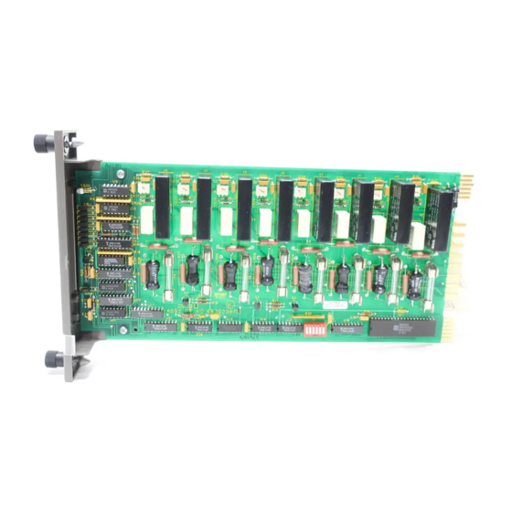
- Page 3 There are four types of DSO modules. This instruction dis- cusses the IMDSO01, IMDSO02 and IMDSO03 modules. Refer to the appropriate instruction for information about the IMDSO04 Digital Output Module. ® INFI 90 is a registered trademark of Elsag Bailey Process Automation. I-E96-310B...
- Page 4 ® List of Effective Pages Total number of pages in this manual is 42, consisting of the following: Page No. Change Date Preface Original List of Effective Pages Original iii through vii Original 1-1 through 1-6 Original 2-1 through 2-6 Original 3-1 through 3-4 Original...
-
Page 5: Table Of Contents
Table of Contents Page SECTION 1 - INTRODUCTION ....................1-1 OVERVIEW ........................1-1 INTENDED USER ......................1-2 MODULE DESCRIPTION ....................1-2 FEATURES........................1-2 INSTRUCTION CONTENT .....................1-3 HOW TO USE THIS INSTRUCTION ................1-3 GLOSSARY OF TERMS AND ABBREVIATIONS .............1-4 REFERENCE DOCUMENTS..................1-4 NOMENCLATURE ......................1-4 SPECIFICATIONS ......................1-5 SECTION 2 - DESCRIPTION AND OPERATION................2-1 INTRODUCTION......................2-1 DIGITAL OUTPUTS.......................2-1 FUNCTIONAL BLOCK DIAGRAM ..................2-1... - Page 6 ® Table of Contents (continued) Page SECTION 5 - TROUBLESHOOTING (continued) Module Status LED ....................5-1 Fuse Status LED ....................5-2 CONTROL MODULE ERRORS ..................5-2 EDGE CONNECTORS ....................5-2 SECTION 6 - MAINTENANCE.....................6-1 INTRODUCTION ......................6-1 PREVENTIVE MAINTENANCE SCHEDULE ..............6-1 EQUIPMENT AND TOOLS REQUIRED ................
- Page 7 List of Figures Title Page 1-1. IMDSO01, IMDSO02 and IMDSO03 Applications ............1-1 2-1. Digital Output Module Block Diagram ..............2-2 2-2. Digital Output Circuit ....................2-2 3-1. DSO Dipswitch and Fuse Locations ................3-2 4-1. DSO Faceplate LEDs ....................4-1 A-1. NTDI01 Component Locations ................A-1 A-2.
- Page 8 ® Safety Summary GENERAL Equipment Environment WARNINGS All components, whether in transportation, operation or storage, must be in a noncorrosive environment. Electrical Shock Hazard During Maintenance Disconnect power or take precautions to insure that contact with energized parts is avoided when servicing. Special Handling This module uses electrostatic sensitive devices.
- Page 9 Sommaire de Sécurité AVERTISSEMENTS Environnement de l’équipement D’ORDRE Ne pas soumettre les composants à une atmosphère corrosive lors GÉNÉRAL du transport, de l’entreposage ou l’utilisation. Possibilité de chocs électriques durant l’entretien Débrancher l’alimentation ou prendre les précautions pour éviter tout contact avec des composants sous tension durant l’entretien. Precautions de manutention Ce module contient des composantes sensibles aux decharges electro-statiques.
-
Page 10: Section 1 - Introduction
SECTION 1 - INTRODUCTION OVERVIEW The IMDSO01, IMDSO02 and IMDSO03 Digital Output (DSO) Modules output eight isolated digital signals from the INFI 90 system to control a process. The signals provide digital switch- ing (on or off) for process field devices. Control modules per- form the control functions and I/O modules provide the input and output signals. -
Page 11: Intended User
INTRODUCTION ® INTENDED USER Personnel installing, operating or maintaining the DSO module should read this instruction before performing any installa- tion, operation or maintenance procedures. Installation requires an engineer or technician with experience handling electronic circuitry and who is familiar with live I/O circuits. MODULE DESCRIPTION The DSO module is an I/O module that outputs eight separate digital signals through solid state relays mounted on the cir-... -
Page 12: Instruction Content
Contains a maintenance schedule for the modules. Repair/Replacement Explains how to replace the modules. Procedures Support Services Explains the customer training Bailey Controls Company pro- vides and information about ordering replacement parts. Appendices Provide information on termination unit and module configu- ration. -
Page 13: Glossary Of Terms And Abbreviations
Table 1-3. Nomenclature Nomenclature Description IEMMU01/02/04 Module mounting unit IMLMM02 Logic master module IMMFP01/02/03 Multi-function processor module NFTP01 Field termination panel ® Network 90 is a registered trademark of Elsag Bailey Process Automation. GLOSSARY OF TERMS AND ABBREVIATIONS 1 - 4 I-E96-310B... -
Page 14: Specifications
INTRODUCTION Table 1-3. Nomenclature (continued) Nomenclature Description NIDI01 Digital input termination module NKTU01 Termination cable, IMDSO01/02/03 to NTDI01 (PVC) NKTU02 Termination cable, IMDSO01/02/03 to NIDI01 (PVC) NKTU11 Termination cable, IMDSO01/02/03 to NTDI01 (non-PVC) NKTU12 Termination cable, IMDSO01/02/03 to NIDI01 (non-PVC) NTDI01 Digital I/O termination unit NTMU01/02... - Page 15 INTRODUCTION ® Table 1-4. Specifications (continued) Property Characteristic/Value IMDSO03 (continued) Max. on voltage drop 2.1 V at 1.0 A, 25°C (77°F) with 0.3-m (1-ft) long termination device cable Max. surge current 2 A for 1 second All IMDSO01/02/03 Isolation 300 VRMS between output and logic circuitry and between outputs. CSA approved for 300 V isolation.
-
Page 16: Section 2 - Description And Operation
SECTION 2 - DESCRIPTION AND OPERATION INTRODUCTION This section explains the digital output circuitry, control logic, data, logic power, and connections for the IMDSO01, IMDSO02 and IMDSO03 Digital Output Module (DSO). The DSO module is a digital signal interface between a control module (multi-function processor module, multi-function controller module, or logic master module) and process field devices. -
Page 17: Digital Output Module Block Diagram
DESCRIPTION AND OPERATION ® close them. The relays follow the output of the registers. Dur- ing normal operation, the DSO module selects the output reg- ister data. Its outputs also turn the front panel output status LEDs on or off. A logic one is inverted by the output block cir- cuits to energize a relay and light an LED. -
Page 18: Output Control Logic
DESCRIPTION AND OPERATION Output Control Logic An output register holds the output data that is sent to the solid state relays. The I/O expander bus interface writes con- trol module data to this register. This data, sent to the data selector block, sets the relay states for normal operation. -
Page 19: Output Circuit Connections
DESCRIPTION AND OPERATION ® LED and is input to the module status buffer. A module reset (remove and insert) clears the latch. Removing the module to replace the fuse resets the fuse status. The status buffer block provides module status information to the control module. -
Page 20: Module Data
DESCRIPTION AND OPERATION MODULE DATA Function code 83 in the control module configuration accesses the DSO module on the I/O expander bus. It also allows the control module to automatically read status data from the I/O module, and write output data to it. The I/O module address in function code 83 must be the same as the address set on the I/O expander bus address dipswitch (dipswitch S1). -
Page 21: Bus Fault Timer
DESCRIPTION AND OPERATION ® BUS FAULT TIMER The bus fault timer is a one-shot timer that is reset by the I/O expander bus clock. The control module generates the bus clock. If the clock stops (indicating a control module error or failure), the bus fault timer times out in ten milliseconds. -
Page 22: Section 3 - Installation
SPECIAL HANDLING Observe the following steps when handling electronic circuitry: NOTE: Always use Bailey's field static kit (part number 1948385_1 - consisting of two wrist straps, ground cord assembly, alligator clip, and static dissipative work surface) when working with the modules. -
Page 23: Unpacking And Inspection
® UNPACKING AND INSPECTION 1. Examine the hardware immediately for shipping damage. 2. Notify the nearest Bailey sales office of any such damage. 3. File a claim for any damage with the transportation com- pany that handled the shipment. 4. Use the original packing material and container to store the hardware. -
Page 24: Dipswitch S1 Settings
INSTALLATION Dipswitch S1 Settings Dipswitch S1 sets the I/O expander bus address of the DSO module. This address uniquely identifies the DSO module to the control module and must be the same as the address set in the control module function block (function code 83, specifica- tion S1) configuration. -
Page 25: Physical Installation
INSTALLATION ® Physical Installation The DSO module inserts into a standard INFI 90 module mounting unit and occupies one slot. Before installing the DSO module, verify the following: 1. Dipswitch S1 is properly configured. 2. All required fuses are functional and properly installed. 3. -
Page 26: Section 4 - Operating Procedures
SECTION 4 - OPERATING PROCEDURES INTRODUCTION This section explains the faceplate LEDs and what they mean. See Figure for the location of the faceplate LEDs on the IMDSO01 module. The IMDSO02 and IMDSO03 modules have the identical faceplate as the IMDSO01 module except for the module nomenclature. -
Page 27: Module Status Led
OPERATING PROCEDURES ® Module Status LED The module status LED is a two-color (red and green) LED. It shows the operating condition of the DSO module. There are three possible operating conditions: No power is being supplied to the DSO module or it is not enabled by the control module. -
Page 28: Section 5 - Troubleshooting
SECTION 5 - TROUBLESHOOTING INTRODUCTION This section explains the error indications and corrective actions for the IMDSO01, IMDSO02 and IMDSO03 Digital Out- put Modules (DSO). ERROR INDICATIONS Troubleshooting is limited to viewing the faceplate LEDs and the module status report from any INFI 90 operator interface. Refer to the product instruction for the operator interface used for information about accessing module status reports. -
Page 29: Fuse Status Led
TROUBLESHOOTING ® Table 5-1. Module Status LED Error Indications and Corrective Actions (continued) LED State Error Indication Probable Cause Corrective Action I/O module not Control module in Put control module into execute mode responding configure mode (continued) (continued) Control module config- Verify function code 83 is in the control uration not correct module configuration... -
Page 30: Edge Connector P1 Pin Assignments
TROUBLESHOOTING Table 5-2. Edge Connector P1 Pin Assignments Signal Signal +5 VDC +5 VDC Unused Unused Common Common Unused Unused Power fail interrupt Power fail interrupt Unused Unused Table 5-3. Edge Connector P2 Pin Assignments Signal Signal Data bit 1 Data bit 0 Data bit 3 Data bit 2... -
Page 31: Section 6 - Maintenance
The reliability of any stand-alone product or control system is affected by the maintenance of the equipment. Bailey Controls Company recommends that all equipment users practice a pre- ventive maintenance program that will keep the equipment operating at an optimum level. -
Page 32: Equipment And Tools Required
MAINTENANCE ® Table 6-1. Preventive Maintenance Schedule Task Frequency Check cabinet air filters. Clean or replace them as neces- 3 months sary. Check the air filter more frequently in excessively dirty environments. Check cabinet and module for dust. Clean as necessary using an antistatic vacuum. -
Page 33: General Cleaning And Washing
MAINTENANCE GENERAL CLEANING AND WASHING If the printed circuit board needs minor cleaning, remove dust and residue from the printed circuit board surface using clean, dry, filtered compressed air or an antistatic field service vac- uum cleaner. Another method of washing the printed circuit board is: 1. -
Page 34: Checking Connections
MAINTENANCE ® Checking Connections Check all signal wiring, power and ground connections within the cabinet to verify their integrity. When checking connec- tions, always turn a screw, nut or other fastening device in the direction to tighten only. If the connection is loose, it will be tightened. -
Page 35: Section 7 - Repair/Replacement Procedures
SECTION 7 - REPAIR/REPLACEMENT PROCEDURES INTRODUCTION If input or output circuits are a shock hazard after disconnect- ing system power at the power entry panel, then the door of the WARNING cabinet containing these externally powered circuits must be marked with a warning stating that multiple power sources exist. -
Page 36: Fuse Replacement Procedure
REPAIR/REPLACEMENT PROCEDURES ® 6. Hold the module by the faceplate and slide it into the assigned slot; push until the rear edges of the module are firmly seated in the backplane connectors. 7. Turn the 2 latching screws on the module -turn to lock the module in place. -
Page 37: Section 8 - Support Services
NTDI02 Digital I/O termination unit NOTE: It is impractical to specify a recommended quantity of spare parts because Bailey custom designs every system. Contact Bailey Controls Company for help determining the quantity of spare parts to keep on hand for your particular system. -
Page 38: Training
SUPPORT SERVICES ® TRAINING Bailey Controls Company has a modern training facility avail- able for training your personnel. On-site training is also avail- able. Contact a Bailey Controls Company sales office for specific information and scheduling. TECHNICAL DOCUMENTATION Additional copies of this instruction, or other Bailey Controls Company instructions, can be obtained from the nearest Bailey Controls Company sales office at a reasonable charge. - Page 39 APPENDIX A - NTDI01 TERMINATION UNIT CONFIGURATION INTRODUCTION The IMDSO01, IMDSO02 and IMDSO03 Digital Output Mod- ules (DSO) can use the NTDI01 Digital I/O Termination Unit (TDI) for termination. Figure shows the location of dip- shunt sockets, fuses, connectors and terminals on the TDI cir- cuit board.
- Page 40 NTDI01 TERMINATION UNIT CONFIGURATION ® Table A-1. NTDI01 Dipshunt Configurations Dipshunt Configuration Application/Signal Type XU1, 3, 5, 7, 9, 11, 13, 15 Externally powered 1 2 3 4 5 6 7 8 System powered from E1 1 2 3 4 5 6 7 8 System powered from E1 (IMDSO02/03) 1 2 3 4 5 6 7 8 System powered from E2 (IMDSO01 only)
-
Page 41: Appendix A - Ntdi01 Termination Unit Configuration
NTDI01 TERMINATION UNIT CONFIGURATION NKTU01 IMDSO01 NKTU11 NTDI01 IMDSO02 IMDSO03 TP21194A Figure A-3. NTDI01 Unit to IMDSO01, IMDSO02 and IMDSO03 Module Connections INTRODUCTION I-E96-310B A - 3... -
Page 42: Appendix B - Nidi01 Termination Module Configuration
APPENDIX B - NIDI01 TERMINATION MODULE CONFIGURATION INTRODUCTION The IMDSO01, IMDSO02 and IMDSO03 Digital Output Mod- ules (DSO) can use the NIDI01 Digital Input Termination Mod- ule (IDI) for termination. Figure shows the location of jumpers, terminals and edge connectors on the IDI circuit board. - Page 43 NIDI01 TERMINATION MODULE CONFIGURATION ® TERMINAL NUMBER 9 10 11 12 13 14 15 16 17 18 19 20 21 22 23 24 25 26 27 28 29 30 31 32 USED USED USED USED USED USED USED TP27160A Figure B-2. NIDI01 Terminal Block Assignments NIDI01 NKTU02 IMDSO01...
- Page 44 Index Abbreviations.............. 1-4 LEDs ................4-1 Applications ..........1-1, A-3, B-2 Fuse status.............4-2, 5-2 Associated equipment ..........1-4 Module status..........4-2, 5-1 Output status ............4-2 Circuit board layout IMDSO01/02/03 module ........3-2 Maintenance NIDI01 module............B-1 Procedures............6-2 NTDI01 unit............A-1 Schedule ...............6-1 Configuration Tools/equipment required ........6-2 IMDSO01/02/03 module ........
- Page 45 Telefax 39-10-6582-941 Telephone 49-69-799-0 Telefax 65-292-9011 Telefax 49-69-799-2406 Form I-E96-310B Litho in U.S.A. 494 Copyright © 1994 by Elsag Bailey Process Automation, As An Unpublished Work ® Registered Trademark of Elsag Bailey Process Automation ™ Trademark of Elsag Bailey Process Automation...
Need help?
Do you have a question about the Infi 90 IMDSO01 and is the answer not in the manual?
Questions and answers