
Related Manuals for Bailey Infi 90 IMDSI12


Summary of Contents for Bailey Infi 90 IMDSI12
- Page 1 IMDSI1 ® ® Digital Input Modules IMDSI12, IMDSI13, IMDSI14, IMDSI15 Process Control and Automation Solutions from Elsag Bailey Group...
- Page 2 The information contained in this document is subject to change without notice. Bailey Controls Company, its affiliates, employees, and agents, and the authors and contributors to this publi- cation specifically disclaim all liabilities and warranties, express and implied (including warranties of mer-...
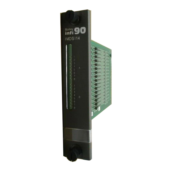
- Page 3 Preface The IMDSI1 Digital Input Module is an interface used to ® bring 16 separate process field signals into the INFI 90 OPEN Strategic Process Management System. These digital inputs are used by control modules to monitor and control a process. This instruction explains the digital input module specifica- tions and operation for the IMDSI12, IMDSI13, IMDSI14 and IMDSI15 modules.
- Page 4 ® List of Effective Pages Total number of pages in this instruction is 46, consisting of the following: Page No. Change Date Preface Original List of Effective Pages Original iii through vii Original 1-1 through 1-8 Original 2-1 through 2-4 Original 3-1 through 3-8 Original...
-
Page 5: Table Of Contents
Table of Contents Page SECTION 1 - INTRODUCTION ....................1-1 OVERVIEW ........................1-1 INTENDED USER ......................1-1 MODULE DESCRIPTION ....................1-2 INSTRUCTION CONTENT .....................1-3 HOW TO USE THIS MANUAL ..................1-3 DOCUMENT CONVENTIONS ..................1-4 GLOSSARY OF TERMS AND ABBREVIATIONS .............1-4 REFERENCE DOCUMENTS..................1-4 NOMENCLATURE ......................1-5 RELATED HARDWARE....................1-5 SPECIFICATIONS ......................1-6 SECTION 2 - DESCRIPTION .......................2-1 INTRODUCTION......................2-1... - Page 6 ® Table of Contents (continued) Page SECTION 6 - MAINTENANCE.....................6-1 INTRODUCTION ......................6-1 PREVENTIVE MAINTENANCE SCHEDULE ..............6-1 EQUIPMENT AND TOOLS REQUIRED ................6-1 PREVENTIVE MAINTENANCE PROCEDURES .............. 6-2 Printed Circuit Board Cleaning ................6-2 General Cleaning and Washing ................ 6-3 Edge Connector Cleaning ................
- Page 7 List of Figures Title Page 1-1. INFI 90 OPEN Communication Levels ..............1-2 2-1. Digital Input Module Block Diagram ...............2-2 2-2. Digital Input Module Circuitry ................2-3 3-1. S1 Address Select Switch Location .................3-3 3-2. Address Select Switch S1 Settings ................3-3 3-3. Cable Connections and Termination ...............3-7 4-1.
- Page 8 ® Safety Summary GENERAL Equipment Environment WARNINGS All components, whether in transportation, operation or storage, must be in a noncorrosive environment. Electrical Shock Hazard During Maintenance Disconnect power or take precautions to insure that contact with energized parts is avoided when servicing. SPECIFIC Disconnect power before installing dipshunts on the MMU back- WARNINGS...
- Page 9 Trademarks and Registrations Registrations and trademarks used in this document include: ® INFI 90 Registered trademark of Elsag Bailey Process Automation ® INFI-NET Registered trademark of Elsag Bailey Process Automation WBPEEUI240752A0...
-
Page 10: Section 1 - Introduction
SECTION 1 - INTRODUCTION OVERVIEW The IMDSI1 Digital Input modules provide 16 separate digital ® signals into the INFI 90 OPEN system for processing and monitoring. It interfaces process field inputs with the INFI 90 OPEN Strategic Process Management System. A contact clo- sure or switch is an example of a device that supplies a digital signal. -
Page 11: Module Description
INTRODUCTION ® COMMUNICATION HIGHWAY (INFI-NET OR PLANT LOOP) COMMUNICATION MODULES CONTROLWAY OTHER MODULES I/O EXPANDER BUS IMCIS 2 IMDSI IMDSO OTHER I/O MODULES TU/TM TU/TM TU/TM T00083A Figure 1-1. INFI 90 OPEN Communication Levels MODULE DESCRIPTION The digital input module consists of a single printed circuit board that occupies one slot in a module mounting unit (MMU). -
Page 12: Instruction Content
Contains scheduled maintenance tasks and procedures. Repair and Replacement Contains procedures that explain how to replace the module. Procedures Support Services Explains the services and training that Elsag Bailey makes available to their customers. Appendices Appendix A provides configuration information for the NTDI01 termination unit. -
Page 13: Document Conventions
IMDSI1 GLOSSARY OF TERMS AND ABBREVIATIONS Table contains those terms and abbreviations that are unique to Elsag Bailey or have a definition that is different from standard industry usage. Table 1-1. Glossary of Terms and Abbreviations Term Definition Engineering work station. -
Page 14: Nomenclature
INTRODUCTION Table 1-2. Reference Documents Number Document I-E92-501-2 Configuration and Tuning Terminal (CTT) I-E96-192-1 Operation, Operator Interface Station (40 Series) IIOIS42 I-E96-200 Function Code Application Manual I-E96-201 Multi-Function Processor (IMMFP01) I-E96-202 Multi-Function Processor (IMMFP02) I-E96-203 Multi-Function Processor (IMMFP03/IMMFP03B) I-E96-209 Logic Master Module (IMLMM02) I-E96-211 IMMFC03 Multi-Function Controller I-E96-212... -
Page 15: Specifications
INTRODUCTION ® Table 1-4. Related Hardware (continued) Nomenclature Description NKTU11 Cable, termination unit (non PVC) NKTU12 Cable, termination module (non PVC) NTDI01 Termination unit, digital input SPECIFICATIONS Table contains the specifications for the IMDSI1 digital input module. Table 1-5. Specifications Property Characteristic/Value Power consumption... - Page 16 INTRODUCTION Table 1-5. Specifications Property Characteristic/Value Isolation Normal (IEC 1010-1, IEC 255, IEC 60) Test Common Mode Mode IMDSI12/15 Channel to channel and channel to Insulation resistance 100 MΩ (100/500 VDC) logic Dielectric VAC (45 - 65 Hz) or 1.4 kV rms/1min. or 1.95 kV DC/1min.
- Page 17 INTRODUCTION ® Table 1-5. Specifications Property Characteristic/Value Magnetic and electromagnetic fields (continued) Radio-frequency common mode, Unmodulated rms: 10 V/m amplitude modulated, 0.15 MHz Amplitude modulated: 80% AM (1 kHz) Source impedance: 150 Ω to 80 MHz (ENV 50141) Emission test Class A RF radiated fields, 30 MHz to 1000 MHz (ENV 55011)
-
Page 18: Section 2 - Description
SECTION 2 - DESCRIPTION INTRODUCTION This section explains the inputs and input circuitry , control logic, logic power and connections for the IMDSI1 Digital Input modules. The DSI is a digital input interface to a multi-function processor (MFP), multi-function controller (MFC), or logic master module (LMM). -
Page 19: Input Circuit Description
DESCRIPTION ® ADDRESS SWITCH LOGIC POWER GROUP A OPEN LEDs GROUP A MODULE CONTROL THRESHOLD INPUT FIELD STATUS LOGIC DETECTION ISOLATION INPUT GROUP B GROUP B LEDs I/O EXPANDER BUS INTERFACE EXPANDER TP65206B Figure 2-1. Digital Input Module Block Diagram Input signal path and low isolation capacitance allow protec- tion against fast transient-burst disturbance. -
Page 20: Input Circuit Connections
DESCRIPTION INPUT CIRCUITRY THRESHOLD AND FILTERING BLOCK +5 VDC +5 VDC VREF JUMPER RESISTORS JUMPER – DIGITAL INPUT DI– +5 VDC NOTE: A = MOUNTED ON IMDSI12 VREF B = MOUNTED ON IMDSI14 C = MOUNTED ON IMDSI13 JUMPER D = MOUNTED ON IMDSI15 ISOLATION T00103A Figure 2-2. -
Page 21: Logic Power
DESCRIPTION ® LOGIC POWER Logic power (+5 VDC) drives the DSI circuits. It connects through the top 12-pin card edge connector (P1) show in Figure 2-1. I/O EXPANDER BUS The INFI 90 OPEN I/O expander bus is a high speed synchro- nous parallel bus. -
Page 22: Section 3 - Installation
NOT PROCEED with operation until you read, understand and complete the steps in the order in which they appear. SPECIAL HANDLING NOTE: Always use the Elsag Bailey field static kit (part number 1948385 1, consisting of two wrist straps, ground cord assembly, alligator clip, and static dissipating work surface when working with static sensitive devices. -
Page 23: Unpacking And Inspection
UNPACKING AND INSPECTION 1. Examine the hardware immediately to verify it has not been damaged in transit. 2. Notify the nearest Elsag Bailey Sales Office of any such damage. 3. File a claim for any damage with the transportation com- pany that handled the shipment. -
Page 24: S1 Address Select Switch Location
INSTALLATION DC/AC MODE VOLTAGE SELECTING JUMPERS (IMDSI12 JUMPERS AND IMDSI15 ONLY) (IMDSI12 ONLY) GROUP A LEDs EDGE CONNECTORS GROUP B LEDs OPEN ADDRESS SWITCH JUMPERS T00104A Figure 3-1. S1 Address Select Switch Location OPEN MUST REMAIN ADDRESS CLOSED NOTE: OPEN POSITION = LOGIC 1 TP65205B Figure 3-2. -
Page 25: S1 Address Switch Settings
INSTALLATION ® Table 3-1. S1 Address Switch Settings (continued) ADDR ADDR 1 = OPEN; 0 = CLOSED IMDSI12 module To set the jumpers for the IMDSI12 module, refer to following procedures. 1. Refer to Table and start with input A1, jumper J1. Move to the right and locate the desired working voltage. -
Page 26: Working Voltage Settings (Imdsi12 Only)
INSTALLATION 2. Repeat step 1 until the jumpers are set for group A and group B inputs. Table 3-2. Working Voltage Settings (IMDSI12 only) 125 VDC/ Input Jumper +24 VDC +48 VDC 120 VAC Table 3-3. DC/AC Mode Settings (IMDSI12 and IMDSI15) Input Jumper AC Mode... -
Page 27: Termination Configuration
INSTALLATION ® NOTE: Due to the number of pins on the P3 connector, 12 inputs are separate while the remaining two pairs share input terminals. The positive (+) side of point 7 and 8 are tied together in each group (refer to Table 5-3). -
Page 28: Wiring Connections And Cabling
INSTALLATION WIRING CONNECTIONS AND CABLING The DSI has three card edge connectors to supply logic power, establish I/O expander bus communication and provide digital inputs (P1, P2, P3 respectively). Wiring Installing the module in the MMU connects the digital input module to the logic power (+5 VDC), necessary to drive the cir- cuitry, at P1. -
Page 29: Preoperating Adjustments
INSTALLATION ® PREOPERATING ADJUSTMENTS The IMDSI1 digital input module does not require any adjustments prior to operation. PREOPERATING ADJUSTMENTS 3 - 8 WBPEEUI240752A0... -
Page 30: Section 4 - Operating Procedures
SECTION 4 - OPERATING PROCEDURES INTRODUCTION This section explains the front panel indicators and start-up procedures for the IMDSI1 digital input module. INDICATORS The DSI module has point (input) status LED indicators on the front panel to aid in system test and diagnosis. There are 16 LEDs divided into two groups of eight (group A and group B). -
Page 31: Section 5 - Troubleshooting
SECTION 5 - TROUBLESHOOTING INTRODUCTION This section explains the error indications and corrective actions for the IMDSI1 Digital Input (DSI) module. ERROR INDICATIONS AND CORRECTIVE ACTION You can obtain the status of the DSI by checking the control module for good quality on its input blocks. Use any INFI 90 OPEN operator interface (e.g., Operator Interface Station, Engineering Work Station, Configuration and Tuning Termi- nal) to do this. -
Page 32: Module Pin Connections
TROUBLESHOOTING ® digital input module and the control module. Verify the bus connection on the MMU back plane. NOTE: If FC 84 specification S3 is set to 0, the control module will trip when the DSI module fails. Changing specification S3 to a 1 will allow the control module to continue to operate when a digital input module fails. -
Page 33: P3 Input Signal Pin Connections
TROUBLESHOOTING Table 5-2. P2 Expander Bus Connections (continued) Pin (P2) Signal Clock Sync NC = Not connected Table 5-3. P3 Input Signal Pin Connections Group A Group B Digital Digital Pin (+) Pin (-) Pin (+) Pin (-) Input Input NOTE: 1. -
Page 34: Preventive Maintenance Schedule
SECTION 6 - MAINTENANCE INTRODUCTION The reliability of any stand-alone product or control system is affected by the maintenance of the equipment. Elsag Bailey recommends that all equipment users practice a preventive maintenance program that will keep the equipment operating at an optimum level. - Page 35 MAINTENANCE ® Table 6-1. Preventive Maintenance Schedule Task Frequency Check cabinet, module mounting unit backplane assem- Every six bly, digital input module and termination device for dust. months or dur- Clean as necessary using an antistatic vacuum. If circuit ing plant shut- board cleaning is necessary, refer to procedure.
- Page 36 MAINTENANCE To wash the printed circuit board: 1. Clean the printed circuit board by spraying or wiping it with isopropyl alcohol (99.5% electronic grade). Use a foam tipped swab to wipe the circuit board. 2. Remove excess solvent by using compressed air to blow it free of the circuit board.
- Page 37 MAINTENANCE ® There are exposed AC and DC connections inside the cabinet. These exposed electrical connections present a shock hazard that can cause injury or death. WARNING If input or output circuits are a shock hazard after disconnect- ing system power at the power entry panel, then the door of the cabinet containing these externally powered circuits must be marked with a warning stating that multiple power sources exist.
- Page 38 SECTION 7 - REPAIR/REPLACEMENT PROCEDURES INTRODUCTION This section explains the replacement procedures for a IMDSI1 Digital Input (DSI) module. There are no special tools required to replace a DSI module. MODULE REPAIR/REPLACEMENT If you determine the DSI is faulty, replace it with a new one. DO NOT try to repair the module;...
- Page 39 SECTION 8 - SUPPORT SERVICES INTRODUCTION Elsag Bailey Process Automation is ready to help in the use and repair of its products. Contact the nearest sales office to make requests for sales, applications, installation, repair, overhaul and maintenance contract services.
-
Page 40: Ntdi01 Termination Unit Dipshunt
APPENDIX A - TERMINATION UNIT (NTDI01) CONFIGURATION INTRODUCTION The IMDSI1 module can use a NTDI01 for termination. Dip- shunts on the NTDI01 Termination Unit configure the digital inputs. The digital input module accepts inputs of 24 VDC, 48 VDC, 125 VDC and 120 VAC, depending on the module selected. - Page 41 TERMINATION UNIT (NTDI01) CONFIGURATION ® Table A-1. NTDI01 Dipshunt Configuration Application/Signal Type Dipshunt Configuration Field powered contact XU1-XU16 XU17 System powered from E1, XU1-XU16 24 VDC, 48 VDC, 125 VDC, 120 VAC XU17 System powered from E2, XU1-XU16 24 VDC, 48 VDC, 125 VDC, 120 VAC XU17 TP27114A...
-
Page 42: Ntdi01 Termination Unit Terminal Assignments
TERMINATION UNIT (NTDI01) CONFIGURATION DIPSHUNT DIPSHUNT DIPSHUNT DIPSHUNT USED USED USED USED XU13 – – – – XU14 XU10 – – – – TERMINAL NUMBER XU15 XU11 – – – – XU16 XU12 – – – – TP27163A Figure A-2. NTDI01 Termination Unit Terminal Assignments INTRODUCTION WBPEEUI240752A0 A - 3... - Page 43 APPENDIX B - TERMINATION MODULE (NIDI01) CONFIGURATION INTRODUCTION The IMDSI1 digital input module can use a NIDI01 for termi- nation. Jumpers on the NIDI01 Termination Module configure the digital inputs. The digital input module accepts inputs of 24 VDC, 48 VDC, 125 VDC and 120 VAC, depending on the module selected.
-
Page 44: S1 Address Select Switch Location And Jumper Locations
APPENDIX C - QUICK REFERENCE INFORMATION INTRODUCTION This section provides a source for reference information. It contains the jumper and switch locations for the IMDSI1 dig- ital input module. Refer to INSTALLATION in Section 3 for a complete description of jumper and switch settings. DC/AC MODE VOLTAGE SELECTING JUMPERS (IMDSI12... - Page 45 QUICK REFERENCE INFORMATION ® Table C-1. S1 Address Switch Settings ADDR ADDR 1 = OPEN; 0 = CLOSED INTRODUCTION C - 2 WBPEEUI240752A0...
-
Page 46: Working Voltage Settings (Imdsi12 Only
QUICK REFERENCE INFORMATION Table C-2. Working Voltage Settings (IMDSI12 only) 125 VDC/ Input Jumper +24 VDC +48 VDC 120 VAC Table C-3. DC/AC Mode Settings (IMDSI12 and IMDSI15) Input Jumper AC Mode DC Mode INTRODUCTION WBPEEUI240752A0 C - 3... - Page 47 Index I/O expander bus interface..........2-4 Input circuit connections ..........2-3 AC/DC mode jumper settings ......3-2, 3-4 Input circuitry...............2-1 Address switch (S1) ..........3-2, 5-1 Installation Ambient temperature ..........1-7 Module ..............3-6 Termination devices ..........3-6 Instruction content............1-3 Intended user ..............1-1 Block diagram, circuitry ..........2-1 Isolation specifications ..........1-7 Cable connections ............
- Page 48 ® Index (continued) Reference documents ..........1-4 Technical documentation..........8-1 Related hardware............1-5 Termination configuration Relative humidity............1-7 Termination module (TM) ........3-6 Replacement parts ............8-1 Termination unit (TU) ..........3-6 Replacement, module ..........7-1 Termination module (TM) ........... 1-4 Termination unit (TU)........1-4, 1-5, A-1 Training...............
- Page 49 Telefax 39-10-6582-941 Telephone 49-69-799-0 Telefax 65-292-9011 Telefax 49-69-799-2406 Form WBPEEUI240752A0 Litho in U.S.A. 1296 Copyright © 1996 by Elsag Bailey Process Automation, As An Unpublished Work ® Registered Trademark of Elsag Bailey Process Automation ™ Trademark of Elsag Bailey Process Automation...
Need help?
Do you have a question about the Infi 90 IMDSI12 and is the answer not in the manual?
Questions and answers